文章目录
1. IgH Master 1.5.2 Documentation
1.1 特性
igh支持以下特性:
-
Designed as a kernel module for Linux 2.6 / 3.x.
-
Implemented according to IEC 61158-12 [2] [3].
-
Comes with EtherCAT-capable native drivers for several common Ethernet chips, as well as a generic driver for all chips supported by the Linux kernel.
// 带有支持EtherCAT的原生驱动程序(native drivers)可用于几种常见的以太网芯片,以及用于Linux内核支持的所有芯片的通用驱动程序(generic driver)。
- The native drivers operate the hardware without interrupts.
    // 原生驱动程序操作硬件时不使用中断。

- Native drivers for additional Ethernet hardware can easily be implemented using the common device interface (see section 4.6) provided by the master module.
    // 使用主模块(master module)提供的通用设备接口(common device interface)(请参阅第4.6节),可以轻松实现用于其他以太网硬件的原生驱动程序(Native drivers)。

- For any other hardware, the generic driver can be used. It uses the lower layers of the Linux network stack.
    // 对于任何其他硬件,可以使用通用驱动程序(generic driver)。 它使用Linux网络堆栈的较低层。
-
The master module supports multiple EtherCAT masters running in parallel.
-
The master code supports any Linux realtime extension through its independent architecture.
- RTAI [11] (including LXRT via RTDM), ADEOS, RT-Preempt [12], Xenomai (including RTDM), etc.
- It runs well even without realtime extensions.
-
Common “Application Interface” for applications, that want to use EtherCAT functionality (see chapter 3).
// 想要使用EtherCAT功能的应用程序使用通用“应用程序接口”(Common “Application Interface”) -
Domains are introduced, to allow grouping of process data transfers with different slave groups and task periods.
// 引入了域,以允许将不同从属组和任务周期传输的过程数据进行分组。
- Handling of multiple domains with different task periods.
    // 处理具有不同任务周期的多个域。

- Automatic calculation of process data mapping, FMMU and sync manager configuration within each domain.
    // 在每个域内自动计算过程数据映射,FMMU和同步管理器配置。
- Communication through several finite state machines.
// 通过几个有限状态机进行通信。
- Automatic bus scanning after topology changes.
    // 拓扑更改后自动进行总线扫描。

- Bus monitoring during operation.
    // 运行期间的总线监视。

- Automatic reconfiguration of slaves (for example after power failure) during operation.
    // 在运行期间自动重新配置从站(例如,断电后)。
- Distributed Clocks support (see section 3.5).
- Configuration of the slave's DC parameters through the application interface.
    // 通过应用程序接口配置从站的DC参数。

- Synchronization (offset and drift compensation) of the distributed slave clocks to the reference clock.
    // 同步分布式从属时钟与参考时钟(偏移和漂移补偿)。

- Optional synchronization of the reference clock to the master clock or the other way round.
    // 参考时钟与主时钟的可选同步,或者相反。
- CANopen over EtherCAT (CoE)
- SDO upload, download and information service.
- Slave configuration via SDOs.
- SDO access from userspace and from the application.

- SDO上传,下载和信息服务。
- 通过SDO进行从站配置。
- 从用户空间和应用程序进行SDO访问。
- Ethernet over EtherCAT (EoE)
- Transparent use of EoE slaves via virtual network interfaces.
- Natively supports either a switched or a routed EoE network architecture.

- 通过虚拟网络接口透明使用EoE从站。
- 本机支持交换式或路由式EoE网络体系结构。
- Vendor-specific over EtherCAT (VoE)
- Communication with vendor-specific mailbox protocols via the API.

- 通过API与供应商特定的邮箱协议进行通信。
- File Access over EtherCAT (FoE)
- Loading and storing files via the command-line tool.
- Updating a slave's firmware can be done easily.

- 通过命令行工具加载和存储文件。
- 更新从站的固件很容易。
- Servo Profile over EtherCAT (SoE)
- Implemented according to IEC 61800-7 [16].
- Storing IDN configurations, that are written to the slave during startup.
- Accessing IDNs via the command-line tool.
- Accessing IDNs at runtime via the the user-space library.

- 根据IEC 61800-7 [16]实施。
- 存储在启动期间写入从站的IDN配置。
- 通过命令行工具访问IDN。
- 在运行时通过用户空间库访问IDN。
- Userspace command-line-tool “ethercat” (see section 7.1)
- Detailed information about master, slaves, domains and bus configuration.
- Setting the master's debug level.
- Reading/Writing alias addresses.
- Listing slave configurations.
- Viewing process data.
- SDO download/upload; listing SDO dictionaries.
- Loading and storing files via FoE.
- SoE IDN access.
- Access to slave registers.
- Slave SII (EEPROM) access.
- Controlling application-layer states.
- Generation of slave description XML and C-code from existing slaves.
- Seamless system integration though LSB compliance.
- Master and network device configuration via sysconfig files.
- Init script for master control.
- Service file for systemd.
- Virtual read-only network interface for monitoring and debugging purposes.
1.2 Architecture
The EtherCAT master is integrated into the Linux kernel. This was an early design decision, which has been made for several reasons:
// EtherCAT主站已集成到Linux内核中。 这是一个早期的设计决定,出于以下几个原因:
-
Kernel code has significantly better realtime characteristics, i. e. less latency than userspace code. It was foreseeable, that a fieldbus master has a lot of cyclic work to do. Cyclic work is usually triggered by timer interrupts inside the kernel. The execution delay of a function that processes timer interrupts is less, when it resides in kernelspace, because there is no need of time-consuming context switches to a userspace process.
// 内核代码具有明显更好的实时特性,例如延迟时间比用户空间代码短。 可以预见,现场总线主站有很多周期性的工作要做。 循环工作通常由内核内部的计时器中断触发。 当它驻留在内核空间中时,处理计时器中断的函数的执行延迟较小,因为不需要费时的上下文切换到用户空间进程。 -
It was also foreseeable, that the master code has to directly communicate with the Ethernet hardware. This has to be done in the kernel anyway (through network device drivers), which is one more reason for the master code being in kernelspace.
// 还可以预见,主代码必须直接与以太网硬件通信。 无论如何,这必须在内核中完成(通过网络设备驱动程序),这也是主代码位于内核空间中的另一个原因。
下图是master架构示意图:

The components of the master environment are described below:
-
Master ModuleKernel module containing one or more EtherCAT master instances(see section 2.1), the “Device Interface” (see section 4.6) and the “Application Interface” (see chapter 3).
//主站模块内核模块,包含一个或多个EtherCAT主站实例(请参见第2.1节),“设备接口”(请参见4.6节)和“应用程序接口”(请参见第3章)。 -
Device ModulesEtherCAT-capable Ethernet device driver modules, that other their devices to the EtherCAT master via the device interface (see section 4.6). These modified network drivers can handle network devices used for EtherCAT operation and “normal” Ethernet devices in parallel. A master can accept a certain device and then is able to send and receive EtherCAT frames. Ethernet devices declined by the master module are connected to the kernel’s network stack as usual.
//设备模块支持EtherCAT的以太网设备驱动程序模块,将其其他设备通过设备接口连接到EtherCAT主站(请参见4.6节)。这些经过修改的网络驱动程序可以并行处理用于EtherCAT操作的网络设备和“常规”以太网设备。主站可以接受某个设备,然后能够发送和接收EtherCAT帧。主模块拒绝的以太网设备照常连接到内核的网络堆栈。 -
ApplicationA program that uses the EtherCAT master (usually for cyclic exchange of process data with EtherCAT slaves). These programs are not part of the EtherCAT master code1, but have to be generated or written by the user. An application can request a master through the application interface (see chapter 3). If this succeeds, it has the control over the master: It can provide a bus configuration and exchange process data. Applications can be kernel modules (that use the kernel application interface directly) or userspace programs, that use the application interface via the EtherCAT library (see section 7.2), or the RTDM library (see section 7.3).
//应用程序使用EtherCAT主站的程序(通常用于与EtherCAT从站循环交换过程数据)。这些程序不是EtherCAT主代码1的一部分,而是必须由用户生成或编写。应用程序可以通过应用程序界面请求主服务器(请参阅第3章)。如果成功,则可以控制主站:它可以提供总线配置并交换过程数据。应用程序可以是内核模块(直接使用内核应用程序接口)或用户空间程序,可以通过EtherCAT库(请参见7.2节)或RTDM库(请参见7.3节)使用应用程序接口。
1.2.1 Master Module
The EtherCAT master kernel module ec_master can contain multiple master instances.
Each master waits for certain Ethernet device(s) identified by its MAC address(es).
These addresses have to be specified on module loading via the main devices (and optional: backup devices) module parameter. The number of master instances to initialize is taken from the number of MAC addresses given.
The below command loads the master module with a single master instance that waits for one Ethernet device with the MAC address 00:0E:0C:DA:A2:20. The master will be accessible via index 0.
// EtherCAT主内核模块ec_master可以包含多个主实例。
每个主机等待由其MAC地址标识的某些以太网设备。
这些地址必须通过主设备(和可选的:备用设备)模块参数在模块加载时指定。 要初始化的主实例的数量来自给定的MAC地址的数量。
以下命令使用一个主实例加载主模块,该主实例等待一个MAC地址为00:0E:0C:DA:A2:20的以太网设备。 主机可以通过索引0访问。
# modprobe ec_master main_devices=00:0E:0C:DA:A2:20
MAC addresses for multiple masters have to be separated by commas:
# modprobe ec_master main_devices=00:0E:0C:DA:A2:20,00:e0:81:71:d5:1c
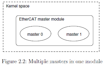
The two masters can be addressed by their indices 0 and 1 respectively (see Figure 2.2). The master index is needed for the ecrt_master_request() function of the application interface (see chapter 3) and the --master option of the ethercat command-line tool (see section 7.1), which defaults to 0.
// 这两个主机可以分别通过其索引0和1进行寻址(见图2.2)。 应用程序界面的ecrt_master_request()函数(请参见第3章)和ethercat命令行工具的–master选项(请参见7.1节)需要master索引,该索引默认为0。
Debug LevelThe master module also has a parameter debug level to set the initial debug level for all masters (see also subsection 7.1.6).
ethercat debug <LEVEL >

Set the master 's debug level .
Debug messages are printed to syslog .
Arguments :
    LEVEL can have one of the following values :
    0 for no debugging output ,
    1 for some debug messages , or
    2 for printing all frame contents (use with caution !).
Numerical values can be specified either with decimal (no prefix ), octal ( prefix '0') or hexadecimal ( prefix '0x ') base .
-
Init ScriptIn most cases it is not necessary to load the master module and the Ethernet driver modules manually. There is an init script available, so the master can be started as a service (see section 7.4). For systems that are managed by systemd [7], there is also a service file available.
// 初始化脚本在大多数情况下,不需要手动加载主模块和以太网驱动程序模块。 有一个可用的初始化脚本,因此可以将主服务器作为服务启动(请参阅第7.4节)。 对于由systemd [7]管理的系统,还有一个服务文件可用。 -
SyslogThe master module outputs information about its state and events to the kernel ring buer. These also end up in the system logs. The above module loading command should result in the messages below:
# dmesg | tail -2
EtherCAT : Master driver 1.5.2
EtherCAT : 2 masters waiting for devices .

# tail -2 /var/log/messages
Jul 4 10:22:45 ethercat kernel : EtherCAT : Master driver 1.5.2
Jul 4 10:22:45 ethercat kernel : EtherCAT : 2 masters waiting for devices .
1.2.2 Master Phases
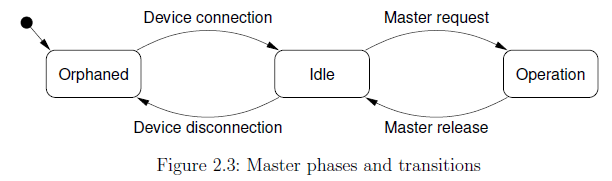
Every EtherCAT master provided by the master module (see section 2.1) runs through several phases (see Figure 2.3):
// 主站模块(请参阅第2.1节)提供的每个EtherCAT主站都经历多个阶段(请参见图2.3):
-
Orphaned phaseThis mode takes effect, when the master still waits for its Ethernet device(s) to connect. No bus communication is possible until then.
// 孤立阶段当主机仍在等待其以太网设备连接时,此模式生效。 在此之前,无法进行总线通讯。 -
Idle phasetakes effect when the master has accepted all required Ethernet devices, but is not requested by any application yet. The master runs its state machine (see section 5.3), that automatically scans the bus for slaves and executespending operations from the userspace interface (for example SDO access). Thecommand-line tool can be used to access the bus, but there is no process data exchange because of the missing bus configuration.
// 当主机已接受所有必需的以太网设备,但尚未被任何应用程序请求时,空闲阶段将生效。 主机运行其状态机(请参阅第5.3节),该状态机自动在总线上扫描从机,并从用户空间接口执行支出操作(例如SDO访问)。 可以使用命令行工具访问总线,但是由于缺少总线配置,因此没有过程数据交换。 -
Operation phaseThe master is requested by an application that can provide a bus configuration and exchange process data.
// 操作阶段主程序由可以提供总线配置并交换过程数据的应用程序请求。
1.2.3 Process Data
This section shall introduce a few terms and ideas how the master handles process data.
// 本节将介绍一些术语和构想,说明主服务器如何处理过程数据。
-
Process Data ImageSlaves offer their inputs and outputs by presenting the master so-called “Process Data Objects” (PDOs). The available PDOs can be either determined by reading out the slave’s TxPDO and RxPDO SII categories from the E2PROM (in case of fixed PDOs) or by reading out the appropriate CoE objects (see section 6.2), if available. The application can register the PDOs’ entries for exchange during cyclic operation. The sum of all registered PDO entries defines the “process data image”, which is exchanged via datagrams with “logical” memory access (like LWR, LRD or LRW) introduced in [2, sec. 5.4].
// 过程数据映像从站通过Master上所谓的“过程数据对象”(PDO)提供其输入和输出。 从机可以通过从E2PROM中读取的TxPDO和RxPDO SII类别(对于固定PDO)来确定可用的PDO,或者通过读取适当的CoE对象(请参见6.2节)来确定。 应用程序可以注册PDO的条目以在循环操作期间进行交换。 所有已注册的PDO条目的总和定义了“过程数据映像”,它通过数据报与在[2,5.4节]中介绍的"逻辑"存储器访问(例如LWR,LRD或LRW)进行交换。 -
Process Data DomainsThe process data image can be easily managed by creating so-called “domains”, which allow grouped PDO exchange. They also take care of managing the datagram structures needed to exchange the PDOs. Domains are mandatory for process data exchange, so there has to be at least one. They were introduced for the following reasons:
// 过程数据域通过创建允许分组的PDO交换的所谓“域”,可以轻松地管理过程数据映像。他们还负责管理交换PDO所需的数据报结构。域对于过程数据交换是必不可少的,因此必须至少有一个。引入它们的原因如下:
- The maximum size of a datagram is limited due to the limited size of an Ethernet frame: The maximum data size is the Ethernet data field size minus the EtherCAT frame header, EtherCAT datagram header and EtherCAT datagram footer: 1500 - 2 - 12 - 2 = 1484 octets. If the size of the process data image exceeds this limit, multiple frames have to be sent, and the image has to be partitioned for the use of multiple datagrams. A domain manages this auto-matically.
//数据报的最大大小由于以太网帧的大小而受到限制:最大数据大小是以太网数据字段的大小减去EtherCAT帧头,EtherCAT数据报头和EtherCAT数据报的页脚:1500-2-12-2 = 1484个八位位组。如果过程数据映像的大小超过此限制,则必须发送多个帧,并且必须对映像进行分区以使用多个数据报。域自动进行管理。

- Not every PDO has to be exchanged with the same frequency: The values of PDOs can vary slowly over time (for example temperature values), so exchanging them with a high frequency would just waste bus bandwidth. For this reason, multiple domains can be created, to group different PDOs and so allow separate exchange.
//并非每个PDO都必须以相同的频率进行交换:PDO的值会随时间缓慢变化(例如温度值),因此以高频率进行交换会浪费总线带宽。因此,可以创建多个域,以将不同的PDO分组,从而允许单独交换。
There is no upper limit for the number of domains, but each domain occupies one FMMU in each slave involved, so the maximum number of domains is de facto limited by the slaves.
//域的数量没有上限,但是每个域在每个涉及的从站中都占用一个FMMU,因此,最大的域数实际上受从站的限制。
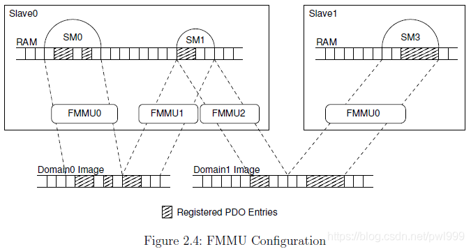
FMMU ConfigurationAn application can register PDO entries for exchange. Every PDO entry and its parent PDO is part of a memory area in the slave’s physical memory, that is protected by a sync manager [2, sec. 6.7] for synchronized access.
// FMMU配置应用程序可以注册PDO条目以进行交换。每个PDO条目及其父PDO都是从站物理内存中存储区域的一部分,该区域由同步管理器保护[2秒。 6.7]用于同步访问。
In order to make a sync manager react on a datagram accessing its memory, it is necessary to access the last byte covered by the sync manager. Otherwise the sync manager will not react on the datagram and no data will be exchanged. That is why the whole synchronized memory area has to be included into the process data image:
// 为了使同步管理器对访问其内存的数据报做出反应,有必要访问同步管理器覆盖的最后一个字节。否则,同步管理器将不会对数据报做出反应,也不会交换任何数据。这就是为什么整个同步存储区必须包含在过程数据映像中的原因:
For example, if a certain PDO entry of a slave is registered for exchange with a certain domain, one FMMU will be configured to map the complete sync-manager-protected memory, the PDO entry resides in. If a second PDO entry of the same slave is registered for process data exchange within the same domain, and it resides in the same sync-manager-protected memory as the first one, the FMMU configuration is not altered, because the desired memory is already part of the domain’s process data image. If the second PDO entry would belong to another sync-manager-protected area, this complete area would also be included into the domains process data image. Figure 2.4 gives an overview, how FMMUs are configured to map physical memory to logical process data images.
// 例如,如果注册了从属服务器的某个PDO条目以与某个域交换,则将配置一个FMMU来映射完整的受同步管理器保护的内存,该PDO条目将驻留在其中。如果同一从属设备的另一个PDO条目在同一域中注册以进行过程数据交换,并且它与第一个存在于相同的受同步管理器保护的存储器中,FMMU配置不会更改,因为所需的存储器已经是域的过程数据映像的一部分。如果第二个PDO条目将属于另一个同步管理器保护的区域,则该完整区域也将包含在域过程数据映像中。图2.4概述了FMMU如何配置为将物理内存映射到逻辑过程数据映像。
1.3 Application Interface
The application interface provides functions and data structures for applications to access an EtherCAT master. The complete documentation of the interface is included as Doxygen [13] comments in the header file include/ecrt.h. It can either be read directly from the file comments, or as a more comfortable HTML documentation.The HTML generation is described in section 9.3.The following sections cover a general description of the application interface.
// 应用程序接口为应用程序提供访问EtherCAT主站的功能和数据结构。 接口的完整文档作为Doxygen [13]注释包含在头文件include / ecrt.h中。 它可以直接从文件注释中读取,也可以作为更舒适的HTML文档读取。第9.3节介绍了HTML的生成。以下各节介绍了应用程序界面的一般说明。
Every application should use the master in two steps:
// 每个应用程序都应分两个步骤使用master:
`Configuration` The master is requested and the configuration is applied. For example, domains are created, slaves are congured and PDO entries are registered (see section 3.1).
// 配置请求主服务器并应用配置。 例如,创建域,配置从站并注册PDO条目(请参阅第3.1节)。

`Operation` Cyclic code is run and process data are exchanged (see section 3.2).
// 操作运行循环代码并交换过程数据(请参阅第3.2节)。
Example Applications There are a few example applications in the examples/sub-directory of the master code. They are documented in the source code.
// 示例应用程序在主代码的“ examples / sub-directory”中有一些示例应用程序。 它们记录在源代码中。
1.3.1 Master Con figuration
The bus confi guration is supplied via the application interface. Figure 3.1 gives an overview of the objects, that can be confi gured by the application.
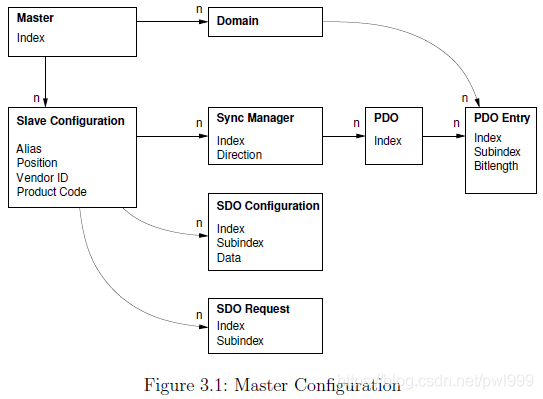
- Slave Con figuration
The application has to tell the master about the expected bus topology. This can be done by creating “slave configurations”. A slave configuration can be seen as an expected slave. When a slave configuration is created, the application provides the bus position (see below), vendor id and product code.
// 该应用程序必须告知主机有关预期的总线拓扑。 这可以通过创建“从站配置”来完成。 从站配置可以视为预期的从站。 创建从站配置后,应用程序将提供总线位置(请参见下文),供应商ID和产品代码。
When the bus configuration is applied, the master checks, if there is a slave with the given vendor id and product code at the given position. If this is the case, the slave configuration is “attached” to the real slave on the bus and the slave is configured according to the settings provided by the application. The state of a slave configuration can either be queried via the application interface or via the command-line tool (see subsection 7.1.3).
// 应用总线配置后,主服务器将检查在给定位置是否存在具有给定供应商ID和产品代码的从属设备。 在这种情况下,从站配置将“附加”到总线上的实际从站,并且根据应用程序提供的设置来配置从站。 可以通过应用程序界面或命令行工具查询从配置的状态(请参见第7.1.3节)。
ethercat config [ OPTIONS ]

Show slave configurations .

Without the -- verbose option , slave configurations are
output one -per - line . Example :
    1001:0 0x0000003b/0x02010000 3   OP
    |      |                     |   |
    |      |                     |   \- Application - layer
    |      |                     |   state of the attached
    |      |                     |   slave , or '-', if no
    |      |                     |   slave is attached .
    |      |                     \- Absolute decimal ring
    |      |                     position of the attached
    |      |                     slave , or '-' if none
    |      |                     attached .
    |      \- Expected vendor ID and product code ( both
    |      hexadecimal ).
    \- Alias address and relative position ( both decimal ).

With the -- verbose option given , the configured PDOs and
SDOs are output in addition .
Configuration selection :
Slave configurations can be selected with
the --alias and -- position parameters as follows :
    1) If neither the --alias nor the -- position option
    is given , all slave configurations are displayed .
    2) If only the -- position option is given , an alias
    of zero is assumed ( see 4)).
    3) If only the --alias option is given , all slave
    configurations with the given alias address
    are displayed .
    4) If both the --alias and the -- position option are
    given , the selection can match a single
    configuration , that is displayed , if it exists .

Command - specific options :
    --alias -a <alias > Configuration alias (see above ).
    -- position -p <pos > Relative position (see above ).
    -- verbose -v Show detailed configurations .
Numerical values can be specified either with decimal (no
prefix ), octal ( prefix '0') or hexadecimal ( prefix '0x ') base .
Slave Position The slave position has to be specified as a tuple of “alias” and “position”. This allows addressing slaves either via an absolute bus position, or a stored identifier called “alias”, or a mixture of both. The alias is a 16-bit value stored in the slave’s E2PROM. It can be modified via the command-line tool (see subsection 7.1.2). Table 3.1 shows, how the values are interpreted.
// 从站位置必须将从站位置指定为“别名”和“位置”的元组。 这允许通过绝对总线位置或存储的称为“别名”的标识符或二者的混合来寻址从站。 别名是存储在从站的E2PROM中的16位值。 可以通过命令行工具对其进行修改(请参见7.1.2小节)。 表3.1显示了如何解释这些值。
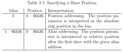
Position addressing. The position parameter is interpreted as the absolute ring position in the bus.
// (Alias = 0)位置寻址。 位置参数被解释为总线中的绝对环位置。

Alias addressing. The position parameter is interpreted as relative position after the first slave with the given alias address.
// (Alias != 0)别名寻址。 position参数被解释为具有给定别名地址的第一个从站之后的相对位置。
Figure 3.2 shows an example of how slave configurations are attached. Some of the configurations were attached, while others remain detached. The below lists gives the reasons beginning with the top slave configuration.
// 图3.2显示了如何附加从站配置的示例。 一些配置已附加,而其他配置仍保持分离。 下面的列表给出了从顶级从站配置开始的原因。
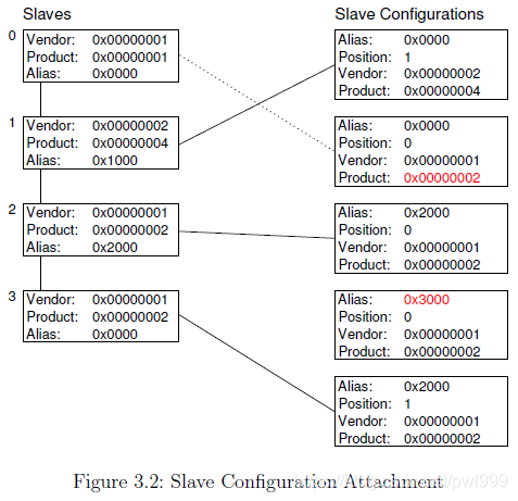
1. A zero alias means to use simple position addressing. Slave 1 exists and vendor id and product code match the expected values.
// 别名为零意味着使用简单的位置寻址。 从站1存在,并且供应商ID和产品代码与期望值匹配。

2. Although the slave with position 0 is found, the product code does not match, so the configuration is not attached.
// .尽管找到了位置为0的从站,但产品代码不匹配,因此未附加组态。

3. The alias is non-zero, so alias addressing is used. Slave 2 is the rst slave with alias 0x2000. Because the position value is zero, the same slave is used.
// 别名非零,因此使用别名寻址。 从站2是别名为0x2000的第一个从站。 由于位置值为零,因此使用相同的从站。

4. There is no slave with the given alias, so the configuration can not be attached.
// 没有具有给定别名的从站,因此无法附加配置。

5. Slave 2 is again the first slave with the alias 0x2000, but position is now 1, so slave 3 is attached.
// 从站2再次是别名为0x2000的第一个从站,但是位置现在为1,因此连接了从站3。
If the master sources are configured with --enable-wildcards, then 0xffffffff matches every vendor ID and/or product code.
// 如果主源配置有–enable-wildcards,则0xffffffff会匹配每个供应商ID和/或产品代码。
1.3.2 Cyclic Operation
To enter cyclic operation mode, the master has to be \activated" to calculate the process data image and apply the bus configuration for the first time. After activation, the application is in charge to send and receive frames. The configuration can not be changed after activation.
// 要进入循环操作模式,必须先“激活主站”以计算过程数据映像并首次应用总线配置。激活后,应用程序负责发送和接收帧。激活后不能更改配置。
1.3.3 VoE Handlers
During the configuration phase, the application can create handlers for the VoE mail-box protocol described in section 6.3. One VoE handler always belongs to a certain slave configuration, so the creation function is a method of the slave configuration.
// 在配置阶段,应用程序可以为6.3节中描述的VoE邮箱协议创建处理程序。一个VoE处理程序始终属于某个从属配置,因此创建功能是从属配置的一种方法。
A VoE handler manages the VoE data and the datagram used to transmit and receive VoE messages. Is contains the state machine necessary to transfer VoE messages.
// VoE handler管理VoE数据和用于发送和接收VoE消息的数据报。是包含传输VoE消息所需的状态机。
The VoE state machine can only process one operation at a time. As a result, either a read or write operation may be issued at a time1. After the operation is initiated, the handler must be executed cyclically until it is finished. After that, the results of the operation can be retrieved.
// VoE状态机一次只能处理一个操作。结果,可以在时间1发出读取或写入操作。启动该操作后,必须循环执行该处理程序,直到完成为止。之后,可以检索操作结果。
A VoE handler has an own datagram structure, that is marked for exchange after each execution step. So the application can decide, how many handlers to execute before sending the corresponding EtherCAT frame(s).
// VoE handler具有自己的数据报结构,该数据报结构被标记为在每个执行步骤之后都可以交换。因此,应用程序可以确定在发送相应的EtherCAT帧之前要执行多少个handler。
For more information about the use of VoE handlers see the documentation of the application interface functions and the example applications provided in the examples/ directory.
// 有关使用VoE处理程序的更多信息,请参见examples /目录中提供的应用程序接口功能和示例应用程序的文档。
1.3.4 Concurrent Master Access
In some cases, one master is used by several instances, for example when an application does cyclic process data exchange, and there are EoE-capable slaves that require to exchange Ethernet data with the kernel (see section 6.1). For this reason, the master is a shared resource, and access to it has to be sequentialized. This is usually done by locking with semaphores, or other methods to protect critical sections.
// 在某些情况下,多个实例使用一个主设备,例如,当应用程序进行循环过程数据交换时,并且有支持EoE的从设备需要与内核交换以太网数据(请参见6.1节)。因此,主服务器是共享资源,必须按顺序对它进行访问。通常,通过使用信号量锁定或其他保护关键部分的方法来完成此操作。
The master itself can not provide locking mechanisms, because it has no chance to know the appropriate kind of lock. For example if the application is in kernelspace and uses RTAI functionality, ordinary kernel semaphores would not be sufficient. For that, an important design decision was made: The application that reserved a master must have the total control, therefore it has to take responsibility for providing the appropriate locking mechanisms. If another instance wants to access the master, it has to request the bus access via callbacks, that have to be provided by the application. Moreover the application can deny access to the master if it considers it to be awkward at the moment.
// 主机本身不能提供锁定机制,因为它没有机会知道适当的锁定类型。例如,如果应用程序在内核空间中并使用RTAI功能,那么普通的内核信号量将不够。为此,做出了一个重要的设计决策:保留主服务器的应用程序必须拥有全部控制权,因此它必须负责提供适当的锁定机制。如果另一个实例想要访问主机,则它必须通过回调请求总线访问,而回调必须由应用程序提供。此外,如果应用程序认为此主机现在很尴尬,则可以拒绝其访问。
Figure 3.3 exemplary shows, how two processes share one master: The application’s cyclic task uses the master for process data exchange, while the master-internal EoE process uses it to communicate with EoE-capable slaves. Both have to access the bus from time to time, but the EoE process does this by “asking” the application to do the bus access for it. In this way, the application can use the appropriate locking mechanism to avoid accessing the bus at the same time. See the application interface documentation (chapter 3) for how to use these callbacks.
// 图3.3示例显示了两个进程如何共享一个主机:应用程序的循环任务使用主机进行进程数据交换,而主机内部的EoE进程使用它与支持EoE的从机进行通信。两者都必须不时访问总线,但是EoE进程通过“询问”应用程序对其进行总线访问来做到这一点。这样,应用程序可以使用适当的锁定机制来避免同时访问总线。有关如何使用这些回调的信息,请参见应用程序接口文档(第3章)。

1.3.5 Distributed Clocks
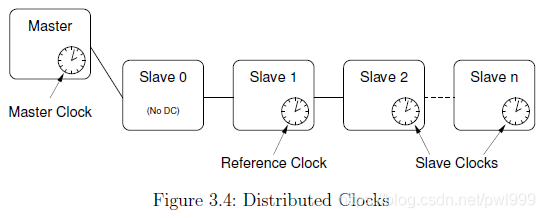
From version 1.5, the master supports EtherCAT’s “Distributed Clocks” feature. It is possible to synchronize the slave clocks on the bus to the “reference clock” (which is the local clock of the first slave with DC support) and to synchronize the reference clock to the “master clock” (which is the local clock of the master). All other clocks on the bus (after the reference clock) are considered as “slave clocks” (see Figure 3.4).
// 从1.5版开始,主站支持EtherCAT的“分布式时钟”功能。 可以将总线上的从时钟同步到“参考时钟”(这是具有DC支持的第一个从时钟的本地时钟),也可以将参考时钟同步到“主时钟”(这是DC的本地时钟)。 大师)。 总线上的所有其他时钟(参考时钟之后)都被视为“从时钟”(见图3.4)。
-
Local ClocksAny EtherCAT slave that supports DC has a local clock register with nanosecond resolution. If the slave is powered, the clock starts from zero, meaning that when slaves are powered on at different times, their clocks will have different values. These “offsets” have to be compensated by the distributed clocks mechanism. On the other hand, the clocks do not run exactly with the same speed, since the used quarts units have a natural frequency deviation. This deviation is usually very small, but over longer periods, the error would accumulate and the difference between local clocks would grow. This clock “drift” has also to be compensated by the DC mechanism.
// 本地时钟任何支持DC的EtherCAT从站都有一个纳秒分辨率的本地时钟寄存器。 如果从站通电,则时钟从零开始,这意味着从站在不同时间通电时,其时钟将具有不同的值。 这些“偏移”必须通过分布式时钟机制进行补偿。 另一方面,由于使用的夸脱单位具有自然的频率偏差,因此时钟的运行速度并不完全相同。 这种偏差通常很小,但是在更长的时间内,误差会累积,本地时钟之间的差异也会增大。 该时钟“漂移”也必须通过DC机制进行补偿。 -
Application TimeThe common time base for the bus has to be provided by the application. This application time tapp is used
// 应用程序时间总线的通用时基必须由应用程序提供。 使用此应用程序时间tapp
1. to configure the slaves' clock offsets (see below),
2. to program the slave's start times for sync pulse generation (see below).
3. to synchronize the reference clock to the master clock (optional).

1.配置从站的时钟偏移(见下文),
2.对从站的启动时间进行编程以生成同步脉冲(请参见下文)。
3.使参考时钟与主时钟同步(可选)。
Offset CompensationFor the offset compensation, each slave provides a “System Time Offset” register toff, that is added to the internal clock value tint to get the “System Time” tsys:
// 失调补偿为了进行失调补偿,每个从机都提供一个“系统时间偏移”寄存器toff,将其添加到内部时钟值tint中以获得“系统时间” tsys:
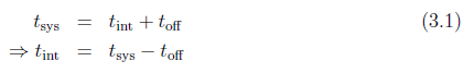
The master reads the values of both registers to calculate a new system time offset in a way, that the resulting system time shall match the master’s application time tapp:
// 主机读取两个寄存器的值以某种方式计算新的系统时间偏移,以使所得的系统时间与主机的应用时间tapp相匹配:
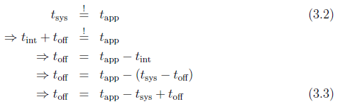
The small time offset error resulting from the different times of reading and writing the registers will be compensated by the drift compensation.
// 由于寄存器的读写时间不同而产生的较小的时间偏移误差将通过漂移补偿得到补偿。
-
Drift CompensationThe drift compensation is possible due to a special mechanism in each DC-capable slave: A write operation to the “System time” register will cause the internal time control loop to compare the written time (minus the programmed transmission delay, see below) to the current system time. The calculated time error will be used as an input to the time controller, that will tune the local clock speed to be a little faster or slower2, according to the sign of the error.
// 漂移补偿可以通过每个具有DC功能的从站中的特殊机制来进行漂移补偿:对“系统时间”寄存器的写操作将使内部时间控制环路比较写入时间(减去编程的传输延迟,请参见下文 )到当前系统时间。 计算出的时间误差将用作时间控制器的输入,时间控制器将根据误差的符号将本地时钟速度调整为更快或更慢2。 -
Transmission DelaysThe Ethernet frame needs a small amount of time to get from slave to slave. The resulting transmission delay times accumulate on the bus and can reach microsecond magnitude and thus have to be considered during the drift compensation. EtherCAT slaves supporting DC provide a mechanism to measure the transmission delays: For each of the four slave ports there is a receive time register.
// 传输延迟以太网帧从从站到从站需要花费少量时间。 由此产生的传输延迟时间会累积在总线上,并可能达到微秒级,因此必须在漂移补偿期间加以考虑。 支持DC的EtherCAT从站提供了一种测量传输延迟的机制:对于四个从端口,每个端口都有一个接收时间寄存器。
A write operation to the receive time register of port 0 starts the measuring and the current system time is latched and stored in a receive time register once the frame is received on the corresponding port. The master can read out the relative receive times, then calculate time delays between the slaves (using its knowledge of the bus topology), and finally calculate the time delays from the reference clock to each slave. These values are programmed into the slaves’ transmission delay registers. In this way, the drift compensation can reach nanosecond synchrony.
// 一旦在相应端口上接收到帧,对端口0的接收时间寄存器的写操作就开始测量,并且当前系统时间被锁存并存储在接收时间寄存器中。 主机可以读取相对接收时间,然后(使用其对总线拓扑的了解)计算从机之间的时间延迟,最后计算从参考时钟到每个从机的时间延迟。 这些值被编程到从站的传输延迟寄存器中。 这样,漂移补偿可以达到纳秒级同步。
Checking SynchronyDC-capable slaves provide the 32-bit “System time difference” register at address 0x092c, where the system time difference of the last drift compensation is stored in nanosecond resolution and in sign-and-magnitude coding3. To check for bus synchrony, the system time difference registers can also be cyclically read via the command-line-tool (see subsection 7.1.14):
// 检查具有同步能力的DC从站在地址0x092c处提供32位“系统时间差”寄存器,其中最后一次漂移补偿的系统时间差以纳秒分辨率和符号幅度编码存储。 要检查总线同步,还可以通过命令行工具循环读取系统时差寄存器(请参见小节7.1.14):
$ watch -n0 "ethercat reg read -p4 -tsm32 0x92c"
Sync SignalsSynchronous clocks are only the prerequisite for synchronous events on the bus. Each slave with DC support provides two “sync signals”, that can be programmed to create events, that will for example cause the slave application to latch its inputs on a certain time. A sync event can either be generated once or cyclically, depending on what makes sense for the slave application. rogramming the sync signals is a matter of setting the so-called “AssignActivate” word and the sync signals’ cycle- and shift times. The AssignActivate word is slave-specific and has to be taken from the XML slave description (Device -> Dc), where also typical sync signal configurations “OpModes” can be found.
// 同步信号同步时钟只是总线上同步事件的前提条件。 每个具有DC支持的从站都提供两个“同步信号”,可以对其进行编程以创建事件,例如,这些事件将导致从属应用程序在特定时间锁存其输入。 同步事件可以一次生成,也可以循环生成,具体取决于对从属应用程序有意义。 设置同步信号的语法是设置所谓的“ AssignActivate”字和同步信号的周期和移位时间的问题。 AssignActivate字是从属特定的,必须从XML从属描述(设备-> Dc)中获取,在该处也可以找到典型的同步信号配置“ OpModes”。
1.4 Ethernet Devices
The EtherCAT protocol is based on the Ethernet standard, so a master relies on standard Ethernet hardware to communicate with the bus.
// EtherCAT协议基于以太网标准,因此主站依靠标准以太网硬件与总线进行通信。
The term device is used as a synonym for Ethernet network interface hardware.
// 术语device被用作以太网网络接口硬件的同义词。
-
Native Ethernet Device DriversThere are native device driver modules (see section 4.2) that handle Ethernet hardware, which a master can use to connect to an EtherCAT bus. They offer their Ethernet hardware to the master module via the device interface (see section 4.6) and must be capable to prepare Ethernet devices either for EtherCAT (realtime) operation or for “normal” operation using the kernel’s network stack. The advantage of this approach is that the master can operate nearly directly on the hardware, which allows a high performance. The disadvantage is, that there has to be an EtherCAT-capable version of the original Ethernet driver.
// 本机以太网设备驱动程序有一些本机设备驱动程序模块(请参阅第4.2节)处理以太网硬件,主机可以使用这些模块连接到EtherCAT总线。他们通过设备接口(请参见4.6节)将其以太网硬件提供给主模块,并且必须能够使用内核的网络堆栈为EtherCAT(实时)操作或“正常”操作准备以太网设备。这种方法的优点是主机可以直接在硬件上直接运行,从而实现高性能。缺点是原始以太网驱动程序必须具有支持EtherCAT的版本。 -
Generic Ethernet Device DriverFrom master version 1.5, there is a generic Ethernet device driver module (see section 4.3), that uses the lower layers of the network stack to connect to the hardware. The advantage is, that arbitrary Ethernet hardware can be used for EtherCAT operation, independently of the actual hardware driver (so all Linux Ethernet drivers are supported without modifications). The disadvantage is, that this approach does not support realtime extensions like RTAI, because the Linux network stack is addressed. Moreover the performance is a little worse than the native approach, because the Ethernet frame data have to traverse the network stack.
// 通用以太网设备驱动程序从主版本1.5开始,有一个通用以太网设备驱动程序模块(请参阅第4.3节),该模块使用网络堆栈的下层连接到硬件。优点是,可以将任意以太网硬件用于EtherCAT操作,而与实际的硬件驱动程序无关(因此,所有Linux以太网驱动程序都无需修改即可支持)。缺点是该方法不支持RTAI等实时扩展,因为已解决了Linux网络堆栈。此外,由于以太网帧数据必须遍历网络堆栈,因此性能比本地方法稍差。
1.4.1 Network Driver Basics
EtherCAT relies on Ethernet hardware and the master needs a physical Ethernet device to communicate with the bus. Therefore it is necessary to understand how Linux handles network devices and their drivers, respectively.
// EtherCAT依赖于以太网硬件,并且主站需要物理以太网设备才能与总线进行通信。因此,有必要了解Linux如何分别处理网络设备及其驱动程序。
-
Tasks of a Network DriverNetwork device drivers usually handle the lower two layers of the OSI model, that is the physical layer and the data-link layer. A network device itself natively handles the physical layer issues: It represents the hardware to connect to the medium and to send and receive data in the way, the physical layer protocol describes. The network device driver is responsible for getting data from the kernel’s networking stack and forwarding it to the hardware, that does the physical transmission. If data is received by the hardware respectively, the driver is notified (usually by means of an interrupt) and has to read the data from the hardware memory and forward it to the network stack. There are a few more tasks, a network device driver has to handle, including queue control, statistics and device dependent features.
// 网络驱动程序的任务网络设备驱动程序通常处理OSI模型的下两层,即物理层和数据链路层。网络设备本身就可以处理物理层问题:物理层协议描述了它代表连接到介质以及以某种方式发送和接收数据的硬件。网络设备驱动程序负责从内核的网络堆栈中获取数据,并将其转发到进行物理传输的硬件。如果数据分别由硬件接收,则通知驱动程序(通常通过中断),并且必须从硬件存储器读取数据并将其转发到网络堆栈。网络设备驱动程序还必须处理一些其他任务,包括队列控制,统计信息和与设备相关的功能。 -
Driver StartupUsually, a driver searches for compatible devices on module loading. For PCI drivers, this is done by scanning the PCI bus and checking for known device IDs. If a device is found, data structures are allocated and the device is taken into operation.
// 驱动程序启动通常,驱动程序会在模块加载时搜索兼容的设备。对于PCI驱动程序,这是通过扫描PCI总线并检查已知设备ID来完成的。如果找到设备,则会分配数据结构并使该设备投入运行。 -
Interrupt OperationA network device usually provides a hardware interrupt that is used to notify the driver of received frames and success of transmission, or errors, respectively. The driver has to register an interrupt service routine (ISR), that is executed each time, the hardware signals such an event. If the interrupt was thrown by the own device (multiple devices can share one hardware interrupt), the reason for the interrupt has to be determined by reading the device’s interrupt register. For example, if the flag for received frames is set, frame data has to be copied from hardware to kernel memory and passed to the network stack.
// 中断操作网络设备通常提供硬件中断,该硬件中断用于分别通知驱动程序接收到的帧以及传输成功或发生错误。驱动程序必须注册一个中断服务程序(ISR),该程序每次在硬件发出此类事件信号时执行。如果中断是由自己的设备抛出的(多个设备可以共享一个硬件中断),则必须通过读取设备的中断寄存器来确定中断的原因。例如,如果设置了接收帧的标志,则必须将帧数据从硬件复制到内核内存,然后传递到网络堆栈。 -
The net_device StructureThe driver registers a net_device structure for each device to communicate with the network stack and to create a “network interface". In case of an Ethernet driver, this interface appears as ethX, where X is a number assigned by the kernel on registration. The net_device structure receives events (either from userspace or from the network stack) via several callbacks, which have to be set before registration. Not every callback is mandatory, but for reasonable operation the ones below are needed in any case:
// net_device结构该驱动程序为每个设备注册一个net_device结构,以便与网络堆栈进行通信并创建“网络接口”,如果是以太网驱动程序,则该接口显示为ethX,其中X是内核在其中分配的数字。 net_device结构通过几个回调接收事件(从用户空间或从网络堆栈),这些回调必须在注册之前进行设置,并非每个回调都是强制性的,但是为了合理的操作,在任何情况下都需要以下回调:
open() This function is called when network communication has to be started, for example after a command ip link set ethX up from userspace. Frame reception has to be enabled by the driver.
// open()当必须启动网络通信时,例如在从用户空间设置ipX命令ethX之后,将调用此函数。帧接收必须由驱动程序启用。

stop() The purpose of this callback is to \close" the device, i. e. make the hardware stop receiving frames.
// stop()该回调的目的是“关闭”设备,即使硬件停止接收帧。

hard_start_xmit() This function is called for each frame that has to be transmitted.The network stack passes the frame as a pointer to an sk_buff structure ("socket buffer", see below), which has to be freed after sending.
// hard_start_xmit()对于必须传输的每个帧都调用此函数。网络堆栈将帧作为指向sk_buff结构(“套接字缓冲区”,见下文)的指针传递,该结构必须在发送后释放。

get_stats() This call has to return a pointer to the device's net_device_stats structure, which permanently has to be lled with frame statistics. This means, that every time a frame is received, sent, or an error happened, the appropriate counter in this structure has to be increased.
// get_stats()此调用必须返回指向设备的net_device_stats结构的指针,该结构必须永久填充帧统计信息。这意味着,每当接收,发送帧或发生错误时,都必须增加此结构中的适当计数器。
The actual registration is done with the register_netdev() call, unregistering is done with unregister_netdev().
// 实际注册是通过register_netdev()调用完成的,注销是通过unregister_netdev()完成的。
-
The netif InterfaceAll other communication in the direction interface -> network stack is done via the netif_*() calls. For example, on successful device opening, the network stack has to be notified, that it can now pass frames to the interface. This is done by calling netif_start_queue(). After this call, the hard_start_xmit() callback can be called by the network stack. Furthermore a network driver usually manages a frame transmission queue. If this gets filled up, the network stack has to be told to stop passing further frames for a while. This happens with a call to netif_stop_queue(). If some frames have been sent, and there is enough space again to queue new frames, this can be notified with netif_wake_queue(). Another important call is netif_receive_skb()1: It passes a frame to the network stack, that was just received by the device. Frame data has to be included in a so-called “socket buffer” for that (see below).
// 所有接口->网络堆栈方向的其他通信都是通过netif _ *()调用完成的。例如,成功打开设备后,必须通知网络堆栈,网络堆栈现在可以将帧传递到接口。这是通过调用netif_start_queue()完成的。调用之后,网络堆栈可以调用hard_start_xmit()回调。此外,网络驱动程序通常管理帧传输队列。如果已填满,则必须告知网络堆栈暂时停止传递其他帧。调用netif_stop_queue()会发生这种情况。如果已经发送了一些帧,并且又有足够的空间来排队新帧,则可以通过netif_wake_queue()进行通知。另一个重要的调用是netif_receive_skb()1:它将帧传递给网络堆栈,该帧刚被设备接收到。为此,帧数据必须包含在所谓的“套接字缓冲区”中(请参见下文)。 -
Socket BuffersSocket buffers are the basic data type for the whole network stack. They serve as containers for network data and are able to quickly add data headers and footers, or strip them off again. Therefore a socket buffer consists of an allocated buffer and several pointers that mark beginning of the buffer (head), beginning of data (data), end of data (tail) and end of buffer (end). In addition, a socket buffer holds network header information and (in case of received data) a pointer to the net_device, it was received on. There exist functions that create a socket buffer (dev_alloc_skb()), add data either from front (skb_push()) or back (skb_put()), remove data from front (skb_pull()) or back (skb_trim()), or delete the buffer (kfree_skb()). A socket buffer is passed from layer to layer, and is freed by the layer that uses it the last time. In case of sending, freeing has to be done by the network driver.
// 套接字缓冲区套接字缓冲区是整个网络堆栈的基本数据类型。它们充当网络数据的容器,并且能够快速添加数据标题和页脚,或再次剥离它们。因此,套接字缓冲区由分配的缓冲区和几个标记缓冲区的指针组成,这些指针标记缓冲区的开始(头),数据的开始(数据),数据的结束(尾)和缓冲区的结束(结束)。另外,套接字缓冲区保存网络标头信息和(在接收到数据的情况下)指向net_device的指针,该信息将在其上被接收。存在创建套接字缓冲区(dev_alloc_skb()),从正面(skb_push())或背面(skb_put())添加数据,从正面(skb_pull())或背面(skb_trim())删除数据的函数,或者删除缓冲区(kfree_skb())。套接字缓冲区从一层传递到另一层,并由上次使用它的层释放。在发送的情况下,必须由网络驱动程序完成释放。
1.4.2 Native EtherCAT Device Drivers
There are a few requirements, that applies to Ethernet hardware when used with anative Ethernet driver with EtherCAT functionality.
// 与具有EtherCAT功能的以太网驱动程序一起使用时,有一些要求适用于以太网硬件。
-
Dedicated HardwareFor performance and realtime purposes, the EtherCAT master needs direct and exclusive access to the Ethernet hardware. This implies that the network device must not be connected to the kernel’s network stack as usual, because the kernel would try to use it as an ordinary Ethernet device.
// 专用硬件为了性能和实时性,EtherCAT主站需要直接和排他地访问以太网硬件。 这意味着网络设备不能像往常一样连接到内核的网络堆栈,因为内核会尝试将其用作普通的以太网设备。 -
Interrupt-less OperationEtherCAT frames travel through the logical EtherCAT ring and are then sent back to the master. Communication is highly deterministic: A frame is sent and will be received again after a constant time, so there is no need to notify the driver about frame reception: The master can instead query the hardware for received frames, if it expects them to be already received. Figure 4.1 shows two work ows for cyclic frame transmission and reception with and without interrupts.
// 无中断运行EtherCAT帧通过逻辑EtherCAT环行,然后发送回主站。 通信是高度确定性的:发送帧并将在固定时间后再次接收,因此无需通知驱动程序有关帧接收的信息:主设备可以代替硬件向硬件查询接收到的帧(如果它希望已接收到帧) 收到。 图4.1显示了有和没有中断的循环帧发送和接收的两个工作流。
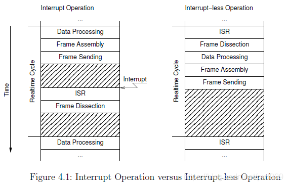
In the left workflow “Interrupt Operation”, the data from the last cycle is first processed and a new frame is assembled with new datagrams, which is then sent. The cyclic work is done for now. Later, when the frame is received again by the hardware, an interrupt is triggered and the ISR is executed. The ISR will fetch the frame data from the hardware and initiate the frame dissection: The datagrams will be processed, so that the data is ready for processing in the next cycle.
// 在左侧的工作流“中断操作”中,首先处理来自最后一个周期的数据,然后将新的帧与新的数据报组装在一起,然后将其发送。循环工作现在已经完成。稍后,当硬件再次接收到该帧时,将触发中断并执行ISR。 ISR将从硬件中获取帧数据并启动帧剖析:将处理数据报,以便准备好在下一个周期中进行处理。
In the right workflow “Interrupt-less Operation”, there is no hardware interrupt enabled. Instead, the hardware will be polled by the master by executing the ISR. If the frame has been received in the meantime, it will be dissected. The situation is now the same as at the beginning of the left workflow: The received data is processed and a new frame is assembled and sent. There is nothing to do for the rest of the cycle.
// 在正确的工作流“无中断操作”中,没有启用硬件中断。相反,硬件将通过执行ISR由主机轮询。如果在此期间已接收到帧,则将其解剖。现在的情况与左工作流程开始时的情况相同:处理接收到的数据,并组装并发送新的帧。在剩余的周期中,没有任何事情要做。
The interrupt-less operation is desirable, because hardware interrupts are not conducive in improving the driver’s realtime behaviour: Their indeterministic incidences contribute to increasing the jitter. Besides, if a realtime extension (like RTAI) is used, some additional effort would have to be made to prioritize interrupts.
// 无中断操作是理想的,因为硬件中断不利于改善驾驶员的实时行为:不确定的事件会增加抖动。此外,如果使用实时扩展(如RTAI),则必须付出一些额外的努力来确定中断的优先级。
Ethernet and EtherCAT DevicesAnother issue lies in the way Linux handles devices of the same type. For example, a PCI driver scans the PCI bus for devices it can handle. Then it registers itself as the responsible driver for all of the devices found. The problem is, that an unmodified driver can not be told to ignore a device because it will be used for EtherCAT later. There must be a way to handle multiple devices of the same type, where one is reserved for EtherCAT, while the other is treated as an ordinary Ethernet device.
// 以太网和EtherCAT设备另一个问题在于Linux处理相同类型设备的方式。例如,PCI驱动程序扫描PCI总线以查找其可以处理的设备。然后,它会将自己注册为找到的所有设备的负责任驱动程序。问题是,无法告知未修改的驱动程序忽略设备,因为该设备稍后将用于EtherCAT。必须有一种方法可以处理多个相同类型的设备,其中一个设备保留用于EtherCAT,而另一个设备则视为普通的以太网设备。
For all this reasons, the author decided that the only acceptable solution is to modify standard Ethernet drivers in a way that they keep their normal functionality, but gain the ability to treat one or more of the devices as EtherCAT-capable. Below are the advantages of this solution:
// 出于所有这些原因,作者认为唯一可接受的解决方案是修改标准以太网驱动程序,使其保持其正常功能,但具有将一个或多个设备视为具有EtherCAT功能的能力。以下是此解决方案的优点:
- No need to tell the standard drivers to ignore certain devices.
- One networking driver for EtherCAT and non-EtherCAT devices.
- No need to implement a network driver from scratch and running into issues, the former developers already solved.
- 无需告诉标准驱动程序忽略某些设备。
- 一个网络驱动程序用于EtherCAT和非EtherCAT设备。
- 以前的开发人员已经解决了,无需从头开始实现网络驱动程序而不会遇到问题。
The chosen approach has the following disadvantages:
// 该方法具有以下缺点:
- The modified driver gets more complicated, as it must handle EtherCAT and non-EtherCAT devices.
- Many additional case differentiations in the driver code.
- Changes and bug fixes on the standard drivers have to be ported to the EtherCAT-capable versions from time to time.
- 修改后的驱动程序变得更加复杂,因为它必须处理EtherCAT和非EtherCAT设备。
- 驱动程序代码中的许多区分判断。
- 对标准驱动程序的更改和错误修复必须不时移植到支持EtherCAT的版本。
1.4.3 Generic EtherCAT Device Driver
Since there are approaches to enable the complete Linux kernel for realtime operation [12], it is possible to operate without native implementations of EtherCAT-capable Ethernet device drivers and use the Linux network stack instead. Figure 2.1 shows the “Generic Ethernet Driver Module”, that connects to local Ethernet devices via the network stack. The kernel module is named ec_generic and can be loaded after the master module like a native EtherCAT-capable Ethernet driver.
// 由于存在使完整的Linux内核实现实时操作的方法[12],因此可以在不具有EtherCAT功能的以太网设备驱动程序的本机实现的情况下进行操作,而是使用Linux网络堆栈。图2.1显示了“通用以太网驱动程序模块”,该模块通过网络堆栈连接到本地以太网设备。内核模块名为ec_generic,可以在主模块之后加载,就像支持EtherCAT的本地以太网驱动程序一样。
The generic device driver scans the network stack for interfaces, that have been registered by Ethernet device drivers. It oers all possible devices to the EtherCAT master. If the master accepts a device, the generic driver creates a packet socket (see man 7 packet) with socket_type set to SOCK_RAW, bound to that device. All functions of the device interface (see section 4.6) will then operate on that socket.
// 通用设备驱动程序会在网络堆栈中扫描以太网设备驱动程序已注册的接口。将所有可能的设备提供给EtherCAT主站。如果主机接受设备,则通用驱动程序会创建一个数据包套接字(请参见man 7数据包),其socket_type设置为SOCK_RAW,并绑定到该设备。然后,设备接口的所有功能(请参见4.6节)将在该插槽上运行。
Below are the advantages of this solution:
// 以下是此解决方案的优点:
- Any Ethernet hardware, that is covered by a Linux Ethernet driver can be used for EtherCAT.
- No modifications have to be made to the actual Ethernet drivers.
- Linux以太网驱动程序涵盖的任何以太网硬件都可以用于EtherCAT。
- 无需修改实际的以太网驱动程序。
The generic approach has the following disadvantages:
// 通用方法具有以下缺点:
- The performance is a little worse than the native approach, because the frame data have to traverse the lower layers of the network stack.
- It is not possible to use in-kernel realtime extensions like RTAI with the generic driver, because the network stack code uses dynamic memory allocations and other things, that could cause the system to freeze in realtime context.
- 性能比本地方法差一点,因为帧数据必须遍历网络堆栈的较低层。
- 不能将RTAI之类的内核内实时扩展与通用驱动程序一起使用,因为网络堆栈代码使用动态内存分配等功能,这可能导致系统在实时上下文中冻结。
Device ActivationIn order to send and receive frames through a socket, the Ethernet device linked to that socket has to be activated, otherwise all frames will be rejected. Activation has to take place before the master module is loaded and can happen in several ways:
// 设备激活为了通过套接字发送和接收帧,必须激活链接到该套接字的以太网设备,否则将拒绝所有帧。 必须在加载主模块之前进行激活,激活可以通过以下几种方式进行:
- Ad-hoc, using the command ip link set dev ethX up (or the older ifconfig ethX up),
- 临时,使用命令ip链接将dev ethX设置为up(或将较旧的ifconfig ethX设置为up),

- Configured, depending on the distribution, for example using ifcfg les (/etc/sysconfig/network/ifcfg-ethX) in openSUSE and others. This is the better choice, if the EtherCAT master shall start at system boot time. Since the Ethernet device shall only be activated, but no IP address etc. shall be assigned, it is enough to use STARTMODE=auto as configuration.
- 根据发行版本进行配置,例如在openSUSE和其他版本中使用ifcfg les(/etc/sysconfig/network/ifcfg-ethX)。 如果EtherCAT主站应在系统启动时启动,则这是更好的选择。 由于仅应激活以太网设备,而不能分配IP地址等,因此使用STARTMODE = auto作为配置就足够了。
1.4.4 Providing Ethernet Devices
After loading the master module, additional module(s) have to be loaded to offer devices to the master(s) (see section 4.6). The master module knows the devices to choose from the module parameters (see section 2.1). If the init script is used to start the master, the drivers and devices to use can be specified in the sysconfig file (see subsection 7.4.2).
// 加载主模块后,必须加载其他模块才能将设备提供给主模块(请参见第4.6节)。 主模块知道要从模块参数中选择的设备(请参见第2.1节)。 如果使用init脚本启动主服务器,则可以在sysconfig文件中指定要使用的驱动程序和设备(请参见7.4.2小节)。
Modules offering Ethernet devices can be
// 提供以太网设备的模块可以是
- native EtherCAT-capable network driver modules (see section 4.2) or
- the generic EtherCAT device driver module (see section 4.3).
- 具有本地EtherCAT功能的网络驱动程序模块(请参阅第4.2节)或
- 通用的EtherCAT设备驱动程序模块(请参见第4.3节)。
1.4.5 Redundancy
Redundant bus operation means, that there is more than one Ethernet connection from the master to the slaves. Process data exchange datagrams are sent out on every master link, so that the exchange is still complete, even if the bus is disconnected somewhere in between.
// 冗余总线操作意味着从主站到从站之间有多个以太网连接。过程数据交换数据报在每个主链路上发送,因此即使总线之间的某个地方断开连接,交换仍将完成。
Prerequisite for fully redundant bus operation is, that every slave can be reached by at least one master link. In this case a single connection failure (i. e. cable break) will never lead to incomplete process data. Double-faults can not be handled with two Ethernet devices.
// 完全冗余总线操作的前提条件是,至少一个主链路可以访问每个从站。在这种情况下,单个连接故障(即电缆断开)将永远不会导致不完整的过程数据。用两个以太网设备不能处理双重故障。
Redundancy is configured with the --with-devices switch at configure time (see chapter 9) and using the backup_devices parameter of the ec_master kernel module (see section 2.1) or the appropriate variable MASTERx_BACKUP in the (sys-)config file (see subsection 7.4.2).
// 在配置时使用–with-devices开关配置冗余(请参见第9章),并使用ec_master内核模块的backup_devices参数(请参见第2.1节)或(sys-)config文件中的相应变量MASTERx_BACKUP(请参见小节)进行配置。 7.4.2)。
Bus scanning is done after a topology change on any Ethernet link. The application interface (see chapter 3) and the command-line tool (see section 7.1) both have methods to query the status of the redundant operation.
// 在任何以太网链路上更改拓扑后,都会执行总线扫描。应用程序界面(请参见第3章)和命令行工具(请参见第7.1节)都具有查询冗余操作状态的方法。
1.4.6 EtherCAT Device Interface
An anticipation to the section about the master module (section 2.1) has to be made in order to understand the way, a network device driver module can connect a device to a specific EtherCAT master.
// 为了了解主模块这一节(第2.1节),必须预见到这一点,网络设备驱动程序模块才能将设备连接到特定的EtherCAT主站。
The master module provides a “device interface” for network device drivers. To use this interface, a network device driver module must include the header devices/ecdev.h, coming with the EtherCAT master code. This header offers a function interface for EtherCAT devices. All functions of the device interface are named with the prefix ecdev.
// 主模块为网络设备驱动程序提供“设备接口”。 要使用此接口,网络设备驱动程序模块必须包含EtherCAT主代码随附的头文件device/ecdev.h。 该头提供了EtherCAT设备的功能接口。 设备接口的所有功能均以前缀ecdev命名。
The documentation of the device interface can be found in the header file or in the appropriate module of the interface documentation (see section 9.3 for generation instructions).
// 设备接口的文档可以在头文件或接口文档的相应模块中找到(有关生成说明,请参见9.3节)。
1.4.7 Patching Native Network Drivers
This section will describe, how to make a standard Ethernet driver EtherCAT-capable, using the native approach (see section 4.2). Unfortunately, there is no standard procedure to enable an Ethernet driver for use with the EtherCAT master, but there are a few common techniques.
// 本节将介绍如何使用原生方法(参见第4.2节)使标准的以太网驱动程序具有EtherCAT功能。不幸的是,没有标准的过程可以使以太网驱动程序与EtherCAT主站一起使用,但是有一些通用技术。
1. A first simple rule is, that netif_*() calls must be avoided for all EtherCAT devices. As mentioned before, EtherCAT devices have no connection to the network stack, and therefore must not call its interface functions.
1.第一个简单的规则是,必须避免对所有EtherCAT设备进行netif _ *()调用。如前所述,EtherCAT设备没有与网络堆栈的连接,因此不得调用其接口功能。

2. Another important thing is, that EtherCAT devices should be operated without interrupts. So any calls of registering interrupt handlers and enabling interrupts at hardware level must be avoided, too.
2.另一个重要的事情是,EtherCAT设备应无中断运行。因此,也必须避免任何在硬件级别注册中断处理程序和启用中断的调用。

3. The master does not use a new socket buffer for each send operation: Instead there is a fix one allocated on master initialization. This socket buffer is filled with an EtherCAT frame with every send operation and passed to the hard_start_xmit() callback. For that it is necessary, that the socket buffer is not be freed by the network driver as usual.
3.master不为每个发送操作使用新的套接字缓冲区:而是在主服务器初始化上分配了一个固定缓冲区。该套接字缓冲区在每次发送操作时都填充有一个EtherCAT帧,并传递给hard_start_xmit()回调。为此,有必要确保网络驱动程序不像往常那样释放套接字缓冲区。
An Ethernet driver usually handles several Ethernet devices, each described by a net_device structure with a priv_data eld to attach driver-dependent data to the structure. To distinguish between normal Ethernet devices and the ones used by EtherCAT masters, the private data structure used by the driver could be extended by a pointer, that points to an ec_device_t object returned by ecdev_offer() (see section 4.6) if the device is used by a master and otherwise is zero.
// 以太网驱动程序通常处理多个以太网设备,每个设备由net_device结构描述,带有priv_data字段,用于将与驱动程序相关的数据附加到该结构。为了区分普通的以太网设备和EtherCAT主设备使用的设备,可以使用指针扩展驱动程序使用的私有数据结构,该指针指向ecdev_offer()返回的ec_device_t对象(请参见4.6节)(如果使用了设备)由一个主,否则为零。
The RealTek RTL-8139 Fast Ethernet driver is a “simple” Ethernet driver and can be taken as an example to patch new drivers. The interesting sections can be found by searching the string “ecdev” in the file devices/8139too-2.6.24-ethercat.c.
// RealTek RTL-8139快速以太网驱动程序是“简单”的以太网驱动程序,可以作为修补新驱动程序的示例。通过在文件devices / 8139too-2.6.24-ethercat.c中搜索字符串“ ecdev”,可以找到有趣的部分。
1.5 State Machines
Many parts of the EtherCAT master are implemented as finite state machines (FSMs). Though this leads to a higher grade of complexity in some aspects, is opens many new possibilities.
// EtherCAT主站的许多部分都实现为有限状态机(FSM)。 尽管这在某些方面导致了更高级别的复杂性,但也打开了许多新的可能性。
The below short code example exemplary shows how to read all slave states and moreover illustrates the restrictions of “sequential” coding:
// 下面的短代码示例示例说明了如何读取所有从属状态,此外还说明了“顺序”编码的限制:
ec_datagram_brd ( datagram , 0x0130 , 2); // prepare datagram
if ( ec_master_simple_io (master , datagram )) return -1;
slave_states = EC_READ_U8 ( datagram -> data ); // process datagram
The ec_master_simple_io() function provides a simple interface for synchronously sending a single datagram and receiving the result1. Internally, it queues the specified datagram, invokes the ec_master_send_datagrams() function to send a frame with the queued datagram and then waits actively for its reception.
// ec_master_simple_io()函数提供了一个简单的接口,用于同步发送单个数据报并接收result1。在内部,它对指定的数据报进行排队,调用ec_master_send_datagrams()函数发送带有排队的数据报的帧,然后主动等待其接收。
This sequential approach is very simple, reflecting in only three lines of code. The disadvantage is, that the master is blocked for the time it waits for datagram reception. There is no difficulty when only one instance is using the master, but if more instances want to (synchronously2) use the master, it is inevitable to think about an alternative to the sequential model.
// 这种顺序方法非常简单,仅反映三行代码。缺点是,主机在等待数据报接收的时间内被阻塞。当只有一个实例正在使用master时,没有任何困难,但是如果有更多实例想要(同步地)使用master,则不可避免地要考虑顺序模型的替代方案。
Master access has to be sequentialized for more than one instance wanting to send and receive datagrams synchronously. With the present approach, this would result in having one phase of active waiting for each instance, which would be non-acceptable especially in realtime circumstances, because of the huge time overhead.
// 对于多个要同步发送和接收数据报的实例,必须对主机访问进行顺序化。使用本方法,这将导致具有一个阶段的活动等待每个实例,这是不可接受的,尤其是在实时情况下,这是因为时间开销很大。
A possible solution is, that all instances would be executed sequentially to queue their datagrams, then give the control to the next instance instead of waiting for the datagram reception. Finally, bus IO is done by a higher instance, which means that all queued datagrams are sent and received. The next step is to execute all instances again, which then process their received datagrams and issue new ones.
// 一种可能的解决方案是,将顺序执行所有实例以将其数据报排队,然后将控制权交给下一个实例,而不是等待数据报接收。最后,总线IO由更高的实例完成,这意味着所有排队的数据报都已发送和接收。下一步是再次执行所有实例,然后处理它们接收的数据报并发出新的数据报。
This approach results in all instances having to retain their state, when giving the control back to the higher instance. It is quite obvious to use a finite state machine model in this case. section 5.1 will introduce some of the theory used, while the listings below show the basic approach by coding the example from above as a state machine:
// 当将控件交还给更高的实例时,此方法导致所有实例必须保留其状态。在这种情况下,使用有限状态机模型是很明显的。 5.1节将介绍一些使用的理论,而下面的清单通过将上面的示例编码为状态机来显示基本方法:
// state 1
ec_datagram_brd ( datagram , 0x0130 , 2); // prepare datagram
ec_master_queue (master , datagram ); // queue datagram
next_state = state_2 ;
// state processing finished
After all instances executed their current state and queued their datagrams, these are sent and received. Then the respective next states are executed:
// 在所有实例执行了它们的当前状态并将它们的数据报排队之后,这些数据包便被发送和接收。然后执行相应的下一个状态:
// state 2
if ( datagram -> state != EC_DGRAM_STATE_RECEIVED ) {
    next_state = state_error ;
    return; // state processing finished
}
slave_states = EC_READ_U8 ( datagram -> data ); // process datagram
// state processing finished .
See section 5.2 for an introduction to the state machine programming concept used in the master code.
// 有关主代码中使用的状态机编程概念的介绍,请参见5.2节。
1.5.1 State Machine Theory
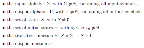
A finite state machine [9] is a model of behavior with inputs and outputs, where the outputs not only depend on the inputs, but the history of inputs. The mathematical definition of a finite state machine (or finite automaton) is a six-tuple with
// 有限状态机[9]是具有输入和输出的行为模型,其中输出不仅取决于输入,而且取决于输入的历史。 有限状态机(或有限自动机)的数学定义是一个六元组,具有
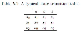
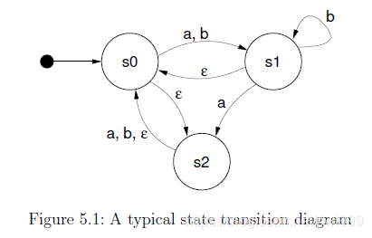
状态转移函数通常由状态转移表或状态转移图指定。状态转移表供了状态机行为的矩阵视图(请参见表5.1)。矩阵行对应于状态(S = {s0; s1; s2}),列对应于输入符号。表内容在第i行和第j列中代表该情况的下一个状态(可能还包括输出),
The state diagram for the same example looks like the one in Figure 5.1. The states are represented as circles or ellipses and the transitions are drawn as arrows between them. Close to a transition arrow can be the condition that must be fulfilled to allow the transition. The initial state is marked by a filled black circle with an arrow pointing to the respective state.
// 同一示例的状态图类似于图5.1中的状态图。 状态用圆圈或椭圆表示,过渡用箭头表示。 靠近过渡箭头可能是满足过渡所必须满足的条件。 初始状态由实心黑色圆圈标记,箭头指向相应状态。
Deterministic and non-deterministic state machines A state machine can be deterministic, meaning that for one state and input, there is one (and only one) following state. In this case, the state machine has exactly one starting state. Non-deterministic state machines can have more than one transitions for a single state-input combination. There is a set of starting states in the latter case.
// 确定性和非确定性状态机状态机。可以是确定性的,这意味着对于一个状态和输入,只有一个(只有一个)跟随状态。 在这种情况下,状态机仅具有一个启动状态。 对于单个状态输入组合,非确定性状态机可以具有多个转换。 在后一种情况下,有一组启动状态。
Moore and Mealy machines There is a distinction between so-called Moore machines, and Mealy machines. Mathematically spoken, the distinction lies in the output function w: .If it only depends on the current state (w : S -> T), the machine corresponds to the “Moore Model”. Otherwise, if w is a function of a state and the input alphabet (w : S x E -> T ) the state machine corresponds to the “Mealy model”. Mealy machines are the more practical solution in most cases, because their design allows machines with a minimum number of states. In practice, a mixture of both models is often used.
// Moore和Mealy机器在所谓的Moore机器和Mealy机器之间有区别。 从数学上讲,区别在于输出函数“ w:”。如果仅取决于当前状态(w:S-> T),则该机器对应于“摩尔模型”。 否则,如果“ w”是状态的函数并且输入字母(w:S x E-> T),则状态机对应于“ Mealy模型”。 在大多数情况下,小型机器是更实用的解决方案,因为它们的设计允许机器具有最少数量的状态。 实际上,经常使用两种模型的混合。
Misunderstandings about state machines There is a phenomenon called “state explosion”, that is often taken as a counter-argument against general use of state machines in complex environments. It has to be mentioned, that this point is misleading [10]. State explosions happen usually as a result of a bad state machine design: Common mistakes are storing the present values of all inputs in a state, or not dividing a complex state machine into simpler sub state machines. The EtherCAT master uses several state machines, that are executed hierarchically and so serve as sub state machines. These are also described below.
// “关于状态机的误解”存在一种称为“状态爆炸”的现象,通常被视为反对在复杂环境中普遍使用状态机的一种说法。 必须指出的是,这一点具有误导性[10]。 状态爆炸通常是由于状态机设计不佳而发生的:常见错误是将所有输入的当前值存储在状态中,或者没有将复杂的状态机划分为更简单的子状态机。 EtherCAT主站使用多个状态机,这些状态机是分层执行的,因此可以用作子状态机。 这些也在下面描述。
1.5.2 The Master’s State Model
This section will introduce the techniques used in the master to implement state machines.
// 本节将介绍master中用于实现状态机的技术。
State Machine Programming There are certain ways to implement a state machine in C code. An obvious way is to implement the different states and actions by one big case differentiation:
// 状态机编程有一些方法可以用C代码实现状态机。 一种明显的方法是通过区分大写来实现不同的状态和动作:
enum { STATE_1 , STATE_2 , STATE_3 };
int state = STATE_1 ;

void state_machine_run (void * priv_data ) {
    switch ( state ) {
        case STATE_1 :
            action_1 ();
            state = STATE_2 ;
            break;
        case STATE_2 :
            action_2 ()
            if ( some_condition ) state = STATE_1 ;
            else state = STATE_3 ;
            break;
        case STATE_3 :
            action_3 ();
            state = STATE_1 ;
            break;
    }
}
For small state machines, this is an option. The disadvantage is, that with an increasing number of states the code soon gets complex and an additional case differentiation is executed each run. Besides, lots of indentation is wasted.
// 对于小型状态机,这是一个选择。 缺点是,随着状态数量的增加,代码很快变得复杂,并且每次运行都会执行额外的区分大小写。 此外,浪费了很多缩进。
The method used in the master is to implement every state in an own function and to store the current state function with a function pointer:
// master中使用的方法是在自己的函数中实现每个状态,并使用函数指针存储当前状态函数:
void (* state )(void *) = state1 ;

void state_machine_run (void * priv_data ) {
    state ( priv_data );
}

void state1 (void * priv_data ) {
    action_1 ();
    state = state2 ;
}

void state2 (void * priv_data ) {
    action_2 ();
    if ( some_condition ) state = state1 ;
    else state = state2 ;
}

void state3 (void * priv_data ) {
    action_3 ();
    state = state1 ;
}
In the master code, state pointers of all state machines are gathered in a single object of the ec_fsm_master_t class. This is advantageous, because there is always one instance of every state machine available and can be started on demand.
// 在master代码中,所有状态机的状态指针都聚集在ec_fsm_master_t类的单个对象中。 这是有利的,因为每个状态机总是存在一个实例,并且可以按需启动。
Mealy and Moore If a closer look is taken to the above listing, it can be seen that the actions executed (the “outputs” of the state machine) only depend on the current state. This accords to the “Moore” model introduced in section 5.1. As mentioned, the “Mealy” model offers a higher exibility, which can be seen in the listing below:
// Mealy和Moore如果仔细查看上面的清单,可以看到执行的动作(状态机的“输出”)仅取决于当前状态。 这符合5.1节中介绍的“Moore”模型。 如前所述,“ Mealy”模型具有更高的适用性,可以在下面的清单中看到:
1 void state7 (void * priv_data ) {
2   if ( some_condition ) {
3       action_7a ();
4       state = state1 ;
5   }
6   else {
7       action_7b ();
8       state = state8 ;
9   }
10 }

3 - 7 The state function executes the actions depending on the state transition, that is about to be done.
The most flexible alternative is to execute certain actions depending on the state, followed by some actions dependent on the state transition:
// 最灵活的选择是根据状态执行某些操作,然后根据状态转换执行一些操作:
void state9 (void * priv_data ) {
    action_9 ();

    if ( some_condition ) {
        action_9a ();
        state = state7 ;
    }
    else {
        action_9b ();
        state = state10 ;
    }
}
This model is often used in the master. It combines the best aspects of both approaches.
// 该模型通常在master中使用。 它结合了两种方法的最佳方面。
Using Sub State Machines To avoid having too much states, certain functions of the EtherCAT master state machine have been sourced out into sub state machines. This helps to encapsulate the related workflows and moreover avoids the “state explosion” phenomenon described in section 5.1. If the master would instead use one big state machine, the number of states would be a multiple of the actual number. This would increase the level of complexity to a non-manageable grade.
// 使用子状态机为避免状态过多,已将EtherCAT主状态机的某些功能提供给子状态机。这有助于封装相关的工作流程,并且避免了5.1节中描述的“状态爆炸”现象。如果主机改为使用一个大状态机,则状态数将是实际数的倍数。这会将复杂性级别提高到无法管理的水平。
Executing Sub State Machines If a state machine starts to execute a sub state machine, it usually remains in one state until the sub state machine terminates. This is usually done like in the listing below, which is taken out of the slave configuration state machine code:
// 执行子状态机如果状态机开始执行子状态机,则通常会保持一种状态,直到子状态机终止。通常,如下面的清单所示,它是从属设备配置状态机代码中删除的:
1 void ec_fsm_slaveconf_safeop ( ec_fsm_t *fsm)
2 {
3   fsm -> change_state (fsm ); // execute state change
4   // sub state machine
5
6   if (fsm -> change_state == ec_fsm_error ) {
7       fsm -> slave_state = ec_fsm_end ;
8       return;
9   }
10
11  if (fsm -> change_state != ec_fsm_end ) return;
12
13  // continue state processing
14  ...

3 change_state is the state pointer of the state change state machine. The state function, the pointer points on, is executed. . .
// 3 change_state是状态更改状态机的状态指针。指针指向的状态函数被执行。 。 。

6 ... either until the state machine terminates with the error state . . .
// 6。 。 。直到状态机以错误状态终止。 。 。

11 ... or until the state machine terminates in the end state. Until then, the "higher" state machine remains in the current state and executes the sub state machine again in the next cycle.
// 11。 。 。或直到状态机终止于结束状态。在此之前,“较高”状态机保持当前状态,并在下一个循环中再次执行子状态机。
State Machine Descriptions The below sections describe every state machine used in the EtherCAT master. The textual descriptions of the state machines contain references to the transitions in the corresponding state transition diagrams, that are marked with an arrow followed by the name of the successive state. Transitions caused by trivial error cases (i. e. no response from slave) are not described explicitly. These transitions are drawn as dashed arrows in the diagrams.
// 状态机描述以下各节描述了EtherCAT主站中使用的每个状态机。状态机的文本描述包含对相应状态转换图中的转换的引用,这些转换标记有箭头,后跟连续状态的名称。由琐碎的错误情况(即,从设备没有响应)引起的转换没有明确描述。这些过渡在图中以虚线箭头绘制。
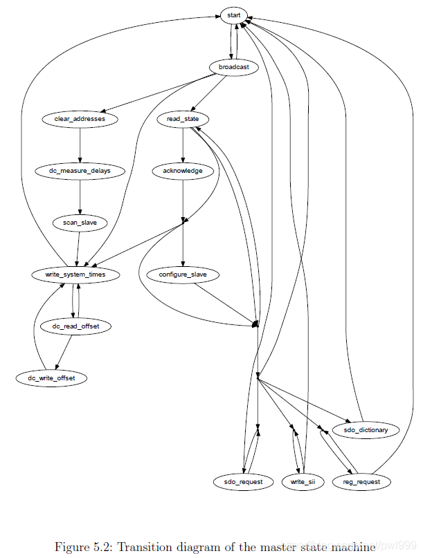
1.5.3 The Master State Machine
The master state machine is executed in the context of the master thread. Figure 5.2 shows its transition diagram. Its purposes are:
// 主状态机在主线程的上下文中执行。 图5.2显示了其过渡图。 其目的是:
Bus monitoring The bus topology is monitored. If it changes, the bus is (re-)scanned.
// 总线监视监视总线拓扑。 如果更改,则对总线进行(重新)扫描。
Slave configuration The application-layer states of the slaves are monitored. If a slave is not in the state it supposed to be, the slave is (re-)configured.
// 从站配置监视从站的应用程序层状态。 如果从站未处于应有的状态,则将(重新)配置该从站。
Request handling Requests (either originating from the application or from external sources) are handled. A request is a job that the master shall process asynchronously, for example an SII access, SDO access, or similar.
// 请求处理处理请求(来自应用程序或来自外部源)。 请求是主机必须异步处理的工作,例如SII访问,SDO访问或类似操作。
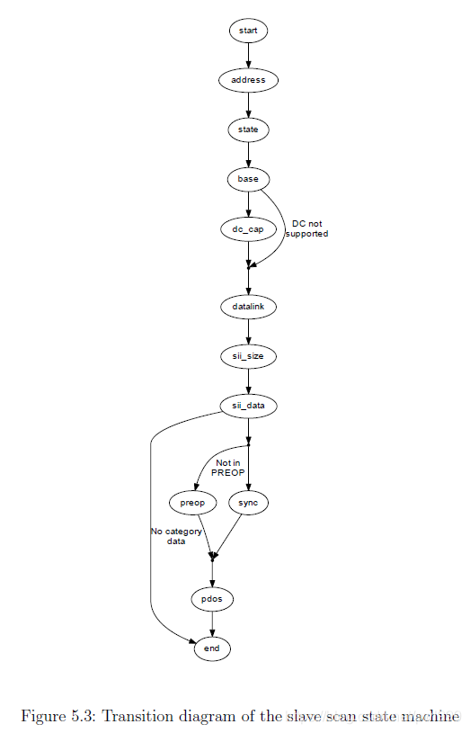
1.5.4 The Slave Scan State Machine
The slave scan state machine, which can be seen in Figure 5.3, leads through the process of reading desired slave information.
// 从机扫描状态机(如图5.3所示)引导着读取所需从机信息的过程。
The scan process includes the following steps:
// 扫描过程包括以下步骤:
Node Address The node address is set for the slave, so that it can be node-addressed for all following operations.
// “节点地址”节点地址是为从站设置的,因此可以为随后的所有操作指定节点地址。
AL State The initial application-layer state is read.
// AL状态读取初始应用层状态。
Base Information Base information (like the number of supported FMMUs) is read from the lower physical memory.
// 基本信息从较低的物理内存中读取基本信息(如支持的FMMU的数量)。
Data Link Information about the physical ports is read.
// 数据链接读取有关物理端口的信息。
SII Size The size of the SII contents is determined to allocate SII image memory.
// “ SII大小”确定SII内容的大小以分配SII图像存储器。
SII Data The SII contents are read into the master’s image.
// `SII数据’SII内容被读入主映像。
PREOP If the slave supports CoE, it is set to PREOP state using the State change FSM (see section 5.6) to enable mailbox communication and read the PDO configuration via CoE.
// PREOP如果从属设备支持CoE,则使用状态更改FSM(请参阅第5.6节)将其设置为PREOP状态,以启用邮箱通信并通过CoE读取PDO配置。
PDOs The PDOs are read via CoE (if supported) using the PDO Reading FSM (see section 5.8). If this is successful, the PDO information from the SII (if any) is overwritten.
// `PDOs’使用PDO读取FSM通过CoE(如果支持)读取PDO(请参见5.8节)。如果成功,则将覆盖来自SII的PDO信息(如果有)。
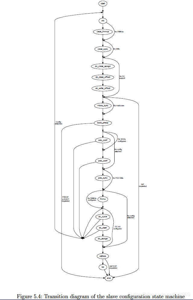
1.5.5 The Slave Con guration State Machine
The slave configuration state machine, which can be seen in Figure 5.4, leads through the process of configuring a slave and bringing it to a certain application-layer state.
// 从机配置状态机(如图5.4所示)引导了配置从机并将其置于特定应用程序层状态的过程。
INIT The state change FSM is used to bring the slave to the INIT state.
// INIT状态改变FSM用于使从机进入INIT状态。
FMMU Clearing To avoid that the slave reacts on any process data, the FMMU configuration are cleared. If the slave does not support FMMUs, this state is skipped. If INIT is the requested state, the state machine is finished.
// “ FMMU清除”为了避免从站对任何过程数据作出反应,将清除FMMU配置。如果从站不支持FMMU,则跳过此状态。如果INIT是请求的状态,则状态机完成。
Mailbox Sync Manager Configuration If the slaves support mailbox communication, the mailbox sync managers are configured. Otherwise this state is skipped.
// 邮箱同步管理器配置如果从服务器支持邮箱通信,则配置邮箱同步管理器。否则,将跳过此状态。
PREOP The state change FSM is used to bring the slave to PREOP state. If this is the requested state, the state machine is finished.
// PREOP状态改变FSM用于使从机进入PREOP状态。如果这是请求的状态,则状态机完成。
SDO Configuration If there is a slave configuration attached (see section 3.1), and there are any SDO configurations are provided by the application, these are sent to the slave.
// “ SDO配置”如果附加了从属配置(请参阅第3.1节),并且应用程序提供了任何SDO配置,则将这些配置发送到从属。
PDO Configuration The PDO configuration state machine is executed to apply all necessary PDO configurations.
// “ PDO配置”执行PDO配置状态机以应用所有必需的PDO配置。
PDO Sync Manager Configuration If any PDO sync managers exist, they are configured.
// “ PDO同步管理器配置”如果存在任何PDO同步管理器,则将对其进行配置。
FMMU Configuration If there are FMMUs configurations supplied by the application (i. e. if the application registered PDO entries), they are applied.
// FMMU配置如果应用程序提供了FMMU配置(即,如果应用程序注册了PDO条目),则将应用它们。
SAFEOP The state change FSM is used to bring the slave to SAFEOP state. If this is the requested state, the state machine is finished.
// SAFEOP状态更改FSM用于使从设备进入SAFEOP状态。如果这是请求的状态,则状态机完成。
OP The state change FSM is used to bring the slave to OP state. If this is the requested state, the state machine is finished.
// `OP’状态更改FSM用于使从设备进入OP状态。如果这是请求的状态,则状态机完成。
1.5.6 The State Change State Machine
The state change state machine, which can be seen in Figure 5.5, leads through the process of changing a slave’s application-layer state. This implements the states and transitions described in [3, sec. 6.4.1].
// 如图5.5所示,状态更改状态机引导着更改从站的应用程序层状态的过程。这实现了[3,sec。中描述的状态和转换。 6.4.1]。
Start The new application-layer state is requested via the "AL Control Request"register (see [3, sec. 5.3.1]).
// “开始”通过“ AL控制请求”寄存器请求新的应用层状态(请参阅[3,第5.3.1节])。
Check for Response Some slave need some time to respond to an AL state change command, and do not respond for some time. For this case, the command is issued again, until it is acknowledged.
// “检查响应”某些从站需要一些时间来响应AL状态更改命令,并且不响应一段时间。对于这种情况,将再次发出命令,直到确认为止。
Check AL Status If the AL State change datagram was acknowledged, the “AL Control Response” register (see [3, sec. 5.3.2]) must be read out until the slave changes the AL state.
// “检查AL状态”如果确认了AL状态更改数据报,则必须读出“ AL控制响应”寄存器(请参阅[3,第5.3.2节]),直到从站更改AL状态为止。
AL Status Code If the slave refused the state change command, the reason can be read from the “AL Status Code” field in the “AL State Changed” registers (see [3, sec. 5.3.3]).
// “ AL状态代码”如果从站拒绝了状态更改命令,则可以从“ AL状态已更改”寄存器中的“ AL状态代码”字段中读取原因(请参阅[3,第5.3.3节])。
Acknowledge State If the state change was not successful, the master has to acknowledge the old state by writing to the “AL Control request” register again.
// “确认状态”如果状态更改失败,则主机必须通过再次写入“ AL控制请求”寄存器来确认旧状态。
Check Acknowledge After sending the acknowledge command, it has to read out the “AL Control Response” register again.
// “检查确认”发送确认命令后,它必须再次读出“ AL控制响应”寄存器。
The “start ack” state is a shortcut in the state machine for the case, that the master wants to acknowledge a spontaneous AL state change, that was not requested.
// “开始确认”状态是状态机的快捷方式,适用于以下情况,即主机希望确认未请求的自发AL状态更改。

1.5.7 The SII State Machine
The SII state machine (shown in Figure 5.6) implements the process of reading or writing SII data via the Slave Information Interface described in [2, sec. 6.4].
// SII状态机(如图5.6所示)实现了通过从机信息接口读取或写入SII数据的过程,该过程在[2,sec。 6.4]。
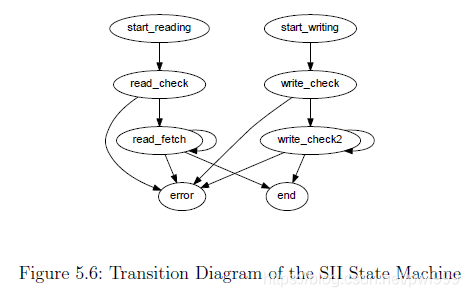
This is how the reading part of the state machine works:
// 这是状态机的读取部分的工作方式:
Start Reading The read request and the requested word address are written to the SII attribute.
// 开始读取将读取请求和请求的字地址写入SII属性。
Check Read Command If the SII read request command has been acknowledged, a timer is started. A datagram is issued, that reads out the SII attribute for state and data.
// 检查读取命令如果已确认SII读取请求命令,则会启动计时器。发出一个数据报,该数据报读取状态和数据的SII属性。
Fetch Data If the read operation is still busy (the SII is usually implemented as an E2PROM), the state is read again. Otherwise the data are copied from the datagram.
// 获取数据如果读取操作仍然很忙(通常将SII实现为E2PROM),则将再次读取状态。否则,数据将从数据报中复制。
The writing part works nearly similar:
// 写作部分的工作原理几乎相似:
Start Writing A write request, the target address and the data word are written to the SII attribute.
// 开始写入将写入请求,目标地址和数据字写入SII属性。
Check Write Command If the SII write request command has been acknowledged, a timer is started. A datagram is issued, that reads out the SII attribute for the state of the write operation.
// 检查写命令如果已确认SII写请求命令,则启动计时器。发出一个数据报,该数据报从SII属性中读取写操作的状态。
Wait while Busy If the write operation is still busy (determined by a minimum wait time and the state of the busy flag), the state machine remains in this state to avoid that another write operation is issued too early.
// 忙时等待如果写操作仍然很忙(由最小等待时间和忙标志的状态决定),则状态机将保持在此状态,以避免过早发出另一个写操作。
1.5.8 The PDO State Machines
The PDO state machines are a set of state machines that read or write the PDO assignment and the PDO mapping via the “CoE Communication Area” described in [3, sec. 5.6.7.4]. For the object access, the CANopen over EtherCAT access primitives are used (see section 6.2), so the slave must support the CoE mailbox protocol.
// PDO状态机是一组状态机,它们通过[3 5.6.7.4]中所述”的“ CoE通信区域”来读取或写入PDO分配和PDO映射。对于对象访问,使用基于EtherCAT的CANopen访问原语(请参见6.2节),因此从站必须支持CoE邮箱协议。
PDO Reading FSM This state machine (Figure 5.7) has the purpose to read the complete PDO configuration of a slave. It reads the PDO assignment for each Sync Manager and uses the PDO Entry Reading FSM (Figure 5.8) to read the mapping for each assigned PDO.
// “ PDO读取FSM”该状态机(图5.7)旨在读取从机的完整PDO配置。它读取每个Sync Manager的PDO分配,并使用PDO Entry Reading FSM(图5.8)读取每个分配的PDO的映射。
Basically it reads the every Sync manager’s PDO assignment SDO’s (0x1C1x) number of elements to determine the number of assigned PDOs for this sync manager and then reads out the subindices of the SDO to get the assigned PDO’s indices. When a PDO index is read, the PDO Entry Reading FSM is executed to read the PDO’s mapped PDO entries.
// 基本上,它会读取每个Sync Manager的PDO分配SDO(0x1C1x)个元素,以确定为此同步管理器分配的PDO数量,然后读取SDO的子索引来获取分配的PDO索引。读取PDO索引后,将执行PDO条目读取FSM,以读取PDO的映射PDO条目。
PDO Entry Reading FSM This state machine (Figure 5.8) reads the PDO mapping (the PDO entries) of a PDO. It reads the respective mapping SDO (0x1600 { 0x17ff, or 0x1a00 { 0x1bff) for the given PDO by reading first the subindex zero (number of elements) to determine the number of mapped PDO entries. After that, each subindex is read to get the mapped PDO entry index, subindex and bit size.
// “ PDO条目读取FSM”此状态机(图5.8)读取PDO的PDO映射(PDO条目)。它通过先读取子索引零(元素数量)来确定映射的PDO条目的数量,从而读取给定PDO的相应映射SDO(0x1600 {0x17ff或0x1a00 {0x1bff))。之后,读取每个子索引以获得映射的PDO条目索引,子索引和位大小。
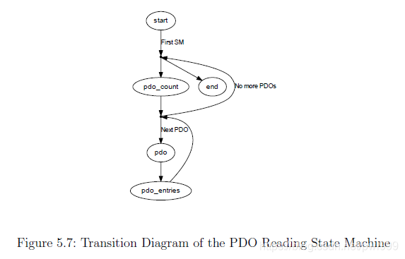
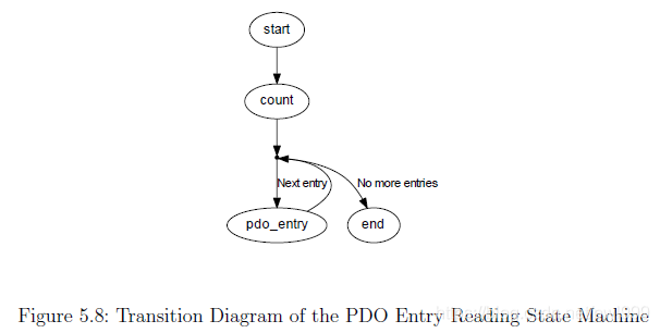
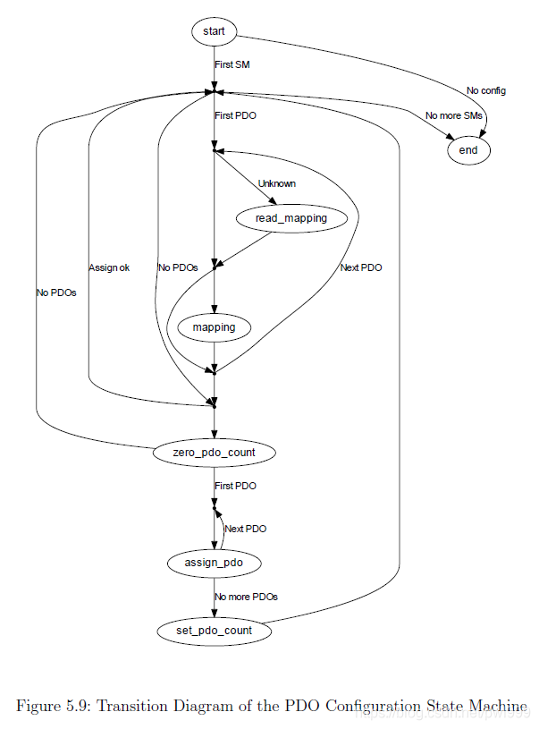

1.6 Mailbox Protocol Implementations
The EtherCAT master implements the CANopen over EtherCAT (CoE), Ethernet over EtherCAT (EoE), File-access over EtherCAT (FoE), Vendor-specific over EtherCAT (VoE) and Servo Profile over EtherCAT (SoE) mailbox protocols. See the below sections for details.
// EtherCAT master实现了CoE、EoE、FoE、VoE、SoE等邮箱协议
1.6.1 Ethernet over EtherCAT (EoE)
The EtherCAT master implements the Ethernet over EtherCAT mailbox protocol [3,sec. 5.7] to enable the tunneling of Ethernet frames to special slaves, that can either have physical Ethernet ports to forward the frames to, or have an own IP stack to receive the frames.
// EtherCAT master实现了在EtherCAT邮箱协议之上传输普通Ethernet,通过隧道的方式传输普通Ethernet帧给某个从机,从站可以把这些帧转发到另一个普通的Ethernet物理端口。这样的从站相当于一个EtherCAT<->Ethernet网关。
Virtual Network InterfacesThe master creates a virtual EoE network interface for every EoE-capable slave. These interfaces are called either
// Master为每个EoE的slave创建一个虚拟EoE网络接口
eoeXsY for a slave without an alias address (see subsection 7.1.2), where X is the master index and Y is the slave’s ring position, or
// slave没有别名地址,X是Master编号,Y是slave的位置
eoeXaY for a slave with a non-zero alias address, where X is the master index and Y is the decimal alias address.
// slave有别名地址,X是Master编号,Y是slave的十进制别名地址
Frames sent to these interfaces are forwarded to the associated slaves by the master. Frames, that are received by the slaves, are fetched by the master and forwarded to the virtual interfaces.
// 发送到这些虚拟网络接口的数据帧由master转发到slave,slave接收到的ethernet数据帧最后由master转发到虚拟网络接口。
This bears the following advantages:
// 这些具有哪些优势:
- Flexibility: The user can decide, how the EoE-capable slaves are interconnected with the rest of the world.
- 灵活性:

- Standard tools can be used to monitor the EoE activity and to congure the EoE interfaces.
- 标准工具

- The Linux kernel's layer-2-bridging implementation (according to the IEEE 802.1D MAC Bridging standard) can be used natively to bridge Ethernet traffic between EoE-capable slaves.

- The Linux kernel's network stack can be used to route packets between EoE-capable slaves and to track security issues, just like having physical network interfaces.
1.6.2 CANopen over EtherCAT (CoE)
The CANopen over EtherCAT protocol [3, sec. 5.6] is used to configure slaves and exchange data objects on application level.
// 在EtherCAT之上实现CANopen协议,用来在应用层级配置slave和交换数据对象。
SDO Download State MachineThe best time to apply SDO configurations is during the slave’s PREOP state, because mailbox communication is already possible and slave’s application will start with updating input data in the succeeding SAFEOP state. Therefore the SDO configuration has to be part of the slave configuration state machine (see section 5.5): It is implemented via an SDO download state machine, that is executed just before entering the slave’s SAFEOP state. In this way, it is guaranteed that the SDO configurations are applied each time, the slave is reconfigured.
// 应用SDO配置最好的时机是slave在pre-operational状态,因为邮箱通信已经ok并且slave应用将要在Safe-operation下更新数据数据。因此SDO配置将会成为slave配置状态机的一部分:它通过SDO下载状态机实现,在进入safe-operation状态之前执行。这样确保每一次SDO配置得到应用,slave被重配置。
The transition diagram of the SDO Download state machine can be seen in Figure 6.2.
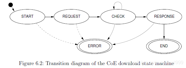
START The beginning state of the CoE download state machine. The “SDO Download Normal Request” mailbox command is sent. -> REQUEST
REQUEST It is checked, if the CoE download request has been received by the slave. After that, a mailbox check command is issued and a timer is started. -> CHECK
CHECK If no mailbox data is available, the timer is checked.
- If it timed out, the SDO download is aborted. -> ERROR
- Otherwise, the mailbox is queried again. -> CHECK
If the mailbox contains new data, the response is fetched. -> RESPONSE
RESPONSE If the mailbox response could not be fetched, the data is invalid, the wrong protocol was received, or a “Abort SDO Transfer Request” was received, the SDO download is aborted. -> ERROR
If a “SDO Download Normal Response” acknowledgement was received, the SDO download was successful. -> END
END The SDO download was successful.
ERROR The SDO download was aborted due to an error.
1.6.3
1.6.4
1.7 Userspace Interfaces
For the master runs as a kernel module, accessing it is natively limited to analyzing Syslog messages and controlling using modutils.
// Master作为一个内核模块来运行,通过modutils来控制并且通过分析Syslog信息来分析。
It was necessary to implement further interfaces, that make it easier to access the master from userspace and allow a finer influence. It should be possible to view and to change special parameters at runtime.
// 它需要实现更多的接口,用来在用户态更加方便的访问master。它可以在运行的时候查看和更改参数。
Bus visualization is another point: For development and debugging purposes it is necessary to show the connected slaves with a single command, for instance (see section 7.1).
// 总线可视化是另外一个点:为了开发和调试目的,需要用单个命令显示出连接的所有slave。
The application interface has to be available in userspace, to allow userspace programs to use EtherCAT master functionality. This was implemented via a character device and a userspace library (see section 7.2).
// 应用接口在用户空间可用,运行用户程序使用EtherCAT master功能。这些通过字符设备和用户空间库来实现
Another aspect is automatic startup and configuration. The master must be able to automatically start up with a persistent configuration (see section 7.4).
// 另一方面是自动启动和配置。master需要使用固定的配置自动启动。
A last thing is monitoring EtherCAT communication. For debugging purposes, there had to be a way to analyze EtherCAT datagrams. The best way would be with a popular network analyzer, like Wireshark [8] or others (see section 7.5).
// 最后一件事是监控EtherCAT通讯。最好的方法是普通的网络分析,类似Wireshark。
This chapter covers all these points and introduces the interfaces and tools to make all that possible.
1.7.1 Command-line Tool
Each master instance will get a character device as a userspace interface. The devices are named /dev/EtherCATx, where x (0 ~ n) is the index of the master.
// 每个master实例使用一个字符设备作为用户空间接口。设备命令为/dev/EtherCATx
Device Node Creation The character device nodes are automatically created, if the udev Package is installed. See section 9.5 for how to install and configure it.
// 在udev安装的情况下,会自动给字符设备创建节点文件。
# 1. Setting Alias Addresses
ethercat alias [ OPTIONS ] <ALIAS >

# 2. Displaying the Bus Conguration
ethercat config [ OPTIONS ]

# 3. Output PDO information in C Language
ethercat cstruct [ OPTIONS ]

# 4. Displaying Process Data
ethercat data [ OPTIONS ]

# 5. Setting a Master's Debug Level
ethercat debug <LEVEL >

# 6. Congured Domains
ethercat domains [ OPTIONS ]

# 7. SDO Access
ethercat download [ OPTIONS ] <INDEX > <SUBINDEX > <VALUE >
[ OPTIONS ] <INDEX > <VALUE >

...
1.7.2 Userspace Library
The native application interface (see chapter 3) resides in kernelspace and hence is only accessible from inside the kernel. To make the application interface available from userspace programs, a userspace library has been created, that can be linked to programs under the terms and conditions of the LGPL, version 2 [5].
// 原生应用接口位于内核空间因此只能在内核下访问。为了让应用接口在用户空间程序有效,用户空间库被创建,它可以在LGPL下链接到程序。
The library is named libethercat. Its sources reside in the lib/ subdirectory and are build by default when using make. It is installed in the lib/ path below the installation prefix as libethercat.a (for static linking), libethercat.la (for the use with libtool ) and libethercat.so (for dynamic linking).
// 这个库命名为libethercat。源代码在lib/目录下。安装lib/目录下的libethercat.a/libethercat.la/libethercat.so。
- Using the Library
The application interface header ecrt.h can be used both in kernel and in user context.
//应用接口头文件ecrt.h在kernel和user上下文中都能使用。
The following minimal example shows how to build a program with EtherCAT functionality. An entire example can be found in the examples/user/ path of the master sources.
//以下是一个小实例用来展示怎么构建一个使用EtherCAT功能的程序。完整的实例可以在examples/user/路径下找到
#include <ecrt .h>
int main (void)
{
    ec_master_t * master = ecrt_request_master (0);

    if (! master )
        return 1; // error

    pause (); // wait for signal
    return 0;
}
The program can be compiled and dynamically linked to the library with the below command:
gcc ethercat.c -o ectest -I/opt/etherlab/include \
    -L/opt/etherlab/lib -lethercat \
    -Wl,--rpath -Wl,/opt/etherlab/lib
The library can also be linked statically to the program:
gcc -static ectest.c -o ectest -I/opt/etherlab/include \
    /opt/etherlab/lib/libethercat.a
- Implementation
Basically the kernel API was transferred into userspace via the master character device (see chapter 2, Figure 2.1 and subsection 7.1.1).
// 基本的kernel API通过字符设备传递到用户空间。
The function calls of the kernel API are mapped to the userspace via an ioctl() interface. The userspace API functions share a set of generic ioctl() calls. The kernel part of the interface calls the according API functions directly, what results in a minimum additional delay (see subsection 7.2.3).
// 函数调用kernel API通过ioctl()映射到用户空间。用户空间API函数共享一系列通用的ioctl()调用。内核直接调用API函数,所以它的延时最小。
For performance reasons, the actual domain process data (see section 2.3) are not copied between kernel and user memory on every access: Instead, the data are memory-mapped to the userspace application. Once the master is configured and activated, the master module creates one process data memory area spanning all domains and maps it to userspace, so that the application can directly access the process data. As a result, there is no additional delay when accessing process data from userspace.
// 因为性能的原因,实际的域过程数据在每次访问时不会在内核空间和用户空间之间拷贝:数据使用memory-mapped来映射到用户空间应用。当master被配置成激活,master module创建一个包含所有域的过程数据内存区域用来映射到用户空间,因此应用能够直接的访问过程数据。所以,用户空间访问过程数据没有额外的延时。
-
Kernel/User API DifferencesBecause of the memory-mapping of the process data, the memory is managed internally by the library functions. As a result, it is not possible to provide external memory for domains, like in the kernel API. The corresponding functions are only available in kernelspace. This is the only difference when using the application interface in userspace.
// 内核和用户API的不同。因为过程数据的memory-mapping,这块内存被库函数内部管理。所以它不可能想内核API一样给域提供外部内存。这是在使用用户空间应用接口时唯一的不同。 -
Timing
An interesting aspect is the timing of the userspace library calls compared to those of the kernel API. Table 7.1 shows the call times and standard deviancies of typical (and time-critical) API functions measured on an Intel Pentium 4 M CPU with 2:2 GHz and a standard 2.6.26 kernel.
// 一个有趣的方面是用户空间库和内核空间API调用时间的比较。下表列出了一个典型实例:
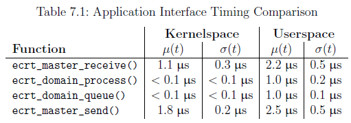
The test results show, that for this configuration, the userspace API causes about 1 us additional delay for each function, compared to the kernel API.
// 用户空间API相比较内核API有1us的延时
1.7.3 RTDM Interface
When using the userspace interfaces of realtime extensions like Xenomai or RTAI, the use of ioctl() is not recommended, because it may disturb realtime operation. To accomplish this, the Real-Time Device Model (RTDM) [17] has been developed. The master module provides an RTDM interface (see Figure 2.1) in addition to the normal character device, if the master sources were configured with --enable-rtdm (see chapter 9).
// 当实时扩展环境(Xenomai or RTAI)下使用用户空间接口时,不推荐使用ioctl(),因为它会妨碍实时操作。为了完成目的,RTDM被开发。master module在普通字符设备基础上额外提供一个RTDM接口,如果master在配置时使用了--enable-rtdm选项。
To force an application to use the RTDM interface instead of the normal character device, it has to be linked with the libethercat rtdm library instead of libethercat. The use of the libethercat rtdm is transparent, so the EtherCAT header ecrt.h with the complete API can be used as usual.
// 为了强制应用使用RTDM接口来替代普通字符设备,它必须链接到rtdm libethercat库用来替代普通的libethercat库。rtdm libethercat库对应用是透明的,所以EtherCAT头文件ecrt.h中定义的API像往常一样使用。
To make the example in Listing 7.1 use the RTDM library, the linker command has to be altered as follows:
gcc ethercat-with-rtdm .c -o ectest -I/opt/etherlab/include \
    -L/opt/etherlab/lib -lethercat_rtdm \
    -Wl ,--rpath -Wl,/opt/etherlab/lib
1.7.4 System Integration
To integrate the EtherCAT master as a service into a running system, it comes with an init script and a sysconfig file, that are described below. Modern systems may be managed by systemd [7]. Integration of the master with systemd is described in subsection 7.4.4.
// 把EtherCAT master当成一个service集成进系统,它由init脚本和sysconfig文件组成。更先进的系统由systemd管理。
- Init Script
The EtherCAT master init script conforms to the requirements of the “Linux Standard Base” (LSB, [6]). The script is installed to etc/init.d/ethercat below the installation prefix and has to be copied (or better: linked) to the appropriate location (see chapter 9), before the master can be inserted as a service. Please note, that the init script depends on the sysconfig file described below.
// EtherCAT master初始化脚本遵循LSB的需求,脚本安装到etc/init.d/ethercat。初始化脚本依赖sysconfig文件
To provide service dependencies (i. e. which services have to be started before others) inside the init script code, LSB defines a special comment block. System tools can extract this information to insert the EtherCAT init script at the correct place in the startup sequence:
// 为了在init脚本中提供service依赖,LSB定义一个特殊的通用模块。系统工具可以解析这些信息,以便决定正确的启动顺序:
# Required - Start : $local_fs $syslog $network
# Should - Start : $time ntp
# Required - Stop : $local_fs $syslog $network
# Should - Stop : $time ntp
# Default - Start : 3 5
# Default - Stop : 0 1 2 6
# Short - Description : EtherCAT master
# Description : EtherCAT master 1.5.2
### END INIT INFO
- Syscon g File
For persistent configuration, the init script uses a sysconfig file installed to etc/sysconfig/ethercat (below the installation prefix), that is mandatory for the init script. The sysconfig file contains all configuration variables needed to operate one or more masters. The documentation is inside the file and included below:
// init脚本使用安装的etc/sysconfig/ethercat sysconfig文件中的固定配置。sysconfig文件包含所有的配置变量
#------------------------------------------------------------------------------

#
# Main Ethernet devices .
#
# The MASTER <X> _DEVICE variable specifies the Ethernet device for a master
# with index 'X '.
#
# Specify the MAC address ( hexadecimal with colons ) of the Ethernet device to
# use. Example : "00:00:08:44: ab :66"
#
# The broadcast address "ff:ff:ff:ff:ff:ff" has a special meaning : It tells
# the master to accept the first device offered by any Ethernet driver .
#
# The MASTER <X> _DEVICE variables also determine , how many masters will be
# created : A non - empty variable MASTER0_DEVICE will create one master , adding a
# non - empty variable MASTER1_DEVICE will create a second master , and so on.
#
MASTER0_DEVICE =""
# MASTER1_DEVICE =""

#
# Backup Ethernet devices
#
# The MASTER <X> _BACKUP variables specify the devices used for redundancy . They
# behaves nearly the same as the MASTER <X> _DEVICE variable , except that it
# does not interpret the ff:ff:ff:ff:ff:ff address .
#
# MASTER0_BACKUP =""

#
# Ethernet driver modules to use for EtherCAT operation .
#
# Specify a non - empty list of Ethernet drivers , that shall be used for
# EtherCAT operation .
#
# Except for the generic Ethernet driver module , the init script will try to
# unload the usual Ethernet driver modules in the list and replace them with
# the EtherCAT - capable ones . If a certain ( EtherCAT - capable ) driver is not
# found , a warning will appear .
#
# Possible values : 8139 too , e100 , e1000 , e1000e , r8169 , generic , ccat , igb .
# Separate multiple drivers with spaces .
#
# Note : The e100 , e1000 , e1000e , r8169 , ccat and igb drivers are not built by
# default . Enable them with the --enable -<driver > configure switches .
#
# Attention : When using the generic driver , the corresponding Ethernet device
# has to be activated ( with OS methods , for example 'ip link set ethX up ') ,
# before the master is started , otherwise all frames will time out.
#
DEVICE_MODULES =""

#
# Flags for loading kernel modules .
#
# This can usually be left empty . Adjust this variable , if you have problems
# with module loading .
#
# MODPROBE_FLAGS ="-b"

#------------------------------------------------------------------------------
For systems managed by systemd (see subsection 7.4.4), the sysconfig file has moved to /etc/ethercat.conf. Both versions are part of the master sources and are meant to used alternatively.
// 对于systemd系统,配置文件移动到/etc/ethercat.conf文件
- Starting the Master as a Service
After the init script and the sysconfig file are placed into the right location, the EtherCAT master can be inserted as a service. The different Linux distributions offer different ways to mark a service for starting and stopping in certain runlevels. For example, SUSE Linux provides the insserv command:
// 不同的linux发行版使用不同的命令来启动和停止service到不同的运行等级。SUSE提供以下命令
# insserv ethercat
The init script can also be used for manually starting and stopping the EtherCAT master. It has to be executed with one of the parameters start, stop, restart or status.
// 手工停止和启动service
# /etc/init.d/ethercat restart
Shutting down EtherCAT master done
Starting EtherCAT master done
- Integration with systemd
Distributions using systemd instead of the SysV init system are using service files to describe how a service is to be maintained. Listing 7.2 lists the master’s service file:
// 某些发行版使用systemd,以下是master的service文件:
#
# EtherCAT master kernel modules
#
[ Unit ]
Description = EtherCAT Master Kernel Modules
#
# Uncomment this , if the generic Ethernet driver is used . It assures , that the
# network interfaces are configured , before the master starts .
#
# Requires = network . service # Stop master , if network is stopped
# After = network . service # Start master , after network is ready
#
# Uncomment this , if a native Ethernet driver is used . It assures , that the
# network interfaces are configured , after the Ethernet drivers have been
# replaced . Otherwise , the networking configuration tools could be confused .
#
# Before = network.service
[ Service ]
Type = oneshot
RemainAfterExit = yes
ExecStart = /opt/etherlab/sbin/ethercatctl start
ExecStop = /opt/etherlab/sbin/ethercatctl stop

[ Install ]
WantedBy = multi-user.target
The ethercatctl command is used to load and unload the master and network driver modules in a similar way to the former init script (subsection 7.4.1). Because it is installed into the sbin/ directory, it can also be used separately:
// ethercatctl命令用来加载和卸载master和网络驱动模块。因为它安装在sbin/目录,所以也可以手工调用
# ethercatctl start
When using systemd and/or the ethercatctl command, the master configuration must be in /etc/ethercat.conf instead of /etc/sysconfig/ethercat! The latter is ignored. The configuration options are exactly the same.
// 当使用systemd的ethercatctl命令时,对应/etc/ethercat.conf配置文件
1.7.5 Debug Interfaces
EtherCAT buses can always be monitored by inserting a switch between master and slaves. This allows to connect another PC with a network monitor like Wireshark [8], for example. It is also possible to listen to local network interfaces on the machine running the EtherCAT master directly. If the generic Ethernet driver (see section 4.3) is used, the network monitor can directly listen on the network interface connected to the EtherCAT bus.
// EtherCAT总线可以在master和slave之间插入一个交换机来做监控,这允许使用网络监控例如Wireshark来连接其他的PC。它也可能直接在master本地网口上进行监听。如果使用generic Ethernet driver,可以监听连接到EtherCAT总线上的本地网络接口。
When using native Ethernet drivers (see section 4.2), there are no local network interfaces to listen to, because the Ethernet devices used for EtherCAT are not registered at the network stack. For that case, so-called “debug interfaces” are supported, which are virtual network interfaces allowing to capture EtherCAT traffic with a network monitor (like Wireshark or tcpdump) running on the master machine without using external hardware. To use this functionality, the master sources have to be configured with the --enable-debug-if switch (see chapter 9).
// 当使用原生EtherCAT驱动,没有本地网络接口可以监听,因为用于EtherCAT的网络设备没有在网络协议栈上注册。对于这种情况,使用"debug interfaces"来支持,它是一个虚拟的网络接口允许抓取EtherCAT传输(类似Wireshark or tcpdump)不需要额外的硬件。使用这个功能,master源码需要使用--enable-debug-if配置选项。
Every EtherCAT master registers a read-only network interface per attached physical Ethernet device. The network interfaces are named ecdbgmX for the main device, and ecdbgbX for the backup device, where X is the master index. The below listing shows a debug interface among some standard network interfaces:
// 每个EtherCAT master注册一个只读的网络接口附加到物理网口上。network interfaces在主设备上命名为ecdbgmX,在备份设备上命名为ecdbgbX。下面是一些debug interface和一些标准的network interfaces:
# ip link

lo: <LOOPBACK ,UP > mtu 16436 qdisc noqueue
 link / loopback 00:00:00:00:00:00 brd 00:00:00:00:00:00
eth0 : <BROADCAST , MULTICAST > mtu 1500 qdisc noop qlen 1000
 link / ether 00:13:46:3 b:ad:d7 brd ff:ff:ff:ff:ff:ff
ecdbgm0 : <BROADCAST , MULTICAST > mtu 1500 qdisc pfifo_fast qlen 1000
 link / ether 00:04:61:03: d1 :01 brd ff:ff:ff:ff:ff:ff
While a debug interface is enabled, all frames sent or received to or from the physical device are additionally forwarded to the debug interface by the corresponding master.
// 当debug interface使能,所有从物理网口发送和接收的数据帧由对应master转发到debug interface。
Network interfaces can be enabled with the below command:
// 网络接口可以使用以下命令使能:
# ip link set dev ecdbgm0 up
Please note, that the frame rate can be very high. With an application connected, the debug interface can produce thousands of frames per second.
// 请注意,帧速率非常高。在应用连接时,debug interface每秒处理几千个数据帧。
Attention The socket buffers needed for the operation of debug interfaces have to be allocated dynamically. Some Linux realtime extensions (like RTAI) do not allow this in realtime context!
// 注意debug interfaces的socket buffer需要动态分配,某些Linux实时扩展不允许在实时上下文中操作。
1.8 Timing Aspects
Although EtherCAT’s timing is highly deterministic and therefore timing issues are rare, there are a few aspects that can (and should be) dealt with.
// 尽管EtherCAT的时间非常确定,因此时间问题非常罕见。但是还是有些方面需要处理。
1.8.1 Application Interface Pro ling
One of the most important timing aspects are the execution times of the application interface functions, that are called in cyclic context. These functions make up an important part of the overall timing of the application. To measure the timing of the functions, the following code was used:
// 最重要的时序方面之一是应用程序接口函数的执行时间,这些时间在循环上下文中调用。 这些功能构成了应用程序总体时序的重要组成部分。 为了测量功能的时序,使用了以下代码:
c0 = get_cycles ();
ecrt_master_receive ( master );
c1 = get_cycles ();
ecrt_domain_process ( domain1 );
c2 = get_cycles ();
ecrt_master_run ( master );
c3 = get_cycles ();
ecrt_master_send ( master );
c4 = get_cycles ();
Between each call of an interface function, the CPU timestamp counter is read. The counter differences are converted to us with help of the cpu_khz variable, that contains the number of increments per ms.
// 在每次调用接口函数之间,都会读取CPU时间戳计数器。 计数器差异在cpu_khz变量的帮助下转换为us,该变量包含每毫秒增量的数量。
For the actual measuring, a system with a 2:0 GHz CPU was used, that ran the above code in an RTAI thread with a period of 100 us. The measuring was repeated n = 100 times and the results were averaged. These can be seen in Table 8.1.
// 为了进行实际测量,使用了具有2:0 GHz CPU的系统,该系统在RTAI线程中以100 us的时间运行上述代码。 重复测量n = 100次,并将结果取平均值。 这些可以在表8.1中看到。
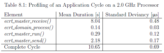
It is obvious, that the functions accessing hardware make up the lion’s share. The ec_master_receive() executes the ISR of the Ethernet device, analyzes datagrams and copies their contents into the memory of the datagram objects. The ec_master_send() assembles a frame out of different datagrams and copies it to the hardware buffers.
// 显而易见,访问硬件的功能构成了最大的份额。 ec_master_receive()执行以太网设备的ISR,分析数据报并将其内容复制到数据报对象的内存中。 ec_master_send()从不同的数据报中组装出一帧并将其复制到硬件缓冲区。
Interestingly, this makes up only a quarter of the receiving time.
// 有趣的是,这仅占接收时间的四分之一。
The functions that only operate on the masters internal data structures are very fast (t < 1 us). Interestingly the runtime of ec_domain_process() has a small standard deviancy relative to the mean value, while this ratio is about twice as big for ec_master_run(): This probably results from the latter function having to execute code depending on the current state and the different state functions are more or less complex.
// 仅对主机内部数据结构起作用的功能非常快(t <1 us)。 有趣的是,ec_domain_process()的运行时相对于平均值具有较小的标准偏差,而该比率大约是ec_master_run()的两倍:这可能是由于后者函数必须根据当前状态和不同情况执行代码而导致的 状态函数或多或少复杂。
For a realtime cycle makes up about 10 us, the theoretical frequency can be up to 100 kHz. For two reasons, this frequency keeps being theoretical:
// 对于大约10 us的实时周期,理论频率可以高达100 kHz。 由于两个原因,该频率一直是理论上的:
1. The processor must still be able to run the operating system between the real-time cycles.
// 1.处理器必须仍然能够在实时周期之间运行操作系统。

2. The EtherCAT frame must be sent and received, before the next realtime cycle begins. The determination of the bus cycle time is difficult and covered in subsection 8.0.2.
// 2.在下一个实时周期开始之前,必须发送和接收EtherCAT帧。 总线循环时间的确定很困难,这在8.0.2小节中有介绍。
1.8.2 Bus Cycle Measuring
For measuring the time, a frame is “on the wire”, two timestamps must be taken:
// 对测量这个时间,数据在线上,两个时间出需要得到
1. The time, the Ethernet hardware begins with physically sending the frame.
// 以太网硬件物理层发送数据帧

2. The time, the frame is completely received by the Ethernet hardware.
// 以太网硬件完成数据帧的接收
Both times are diffcult to determine. The first reason is, that the interrupts are disabled and the master is not notified, when a frame is sent or received (polling would distort the results). The second reason is, that even with interrupts enabled, the time from the event to the notification is unknown. Therefore the only way to confidently determine the bus cycle time is an electrical measuring.
// 所有的时间都非常难以确定。第一个原因是中断被屏蔽,当一个数据帧发送和接收时master没有通知(轮询会歪曲结果)。第二个原因是,就算中断使能,这个通知事件的时间也是未知。因此唯一确定总线周期的方法就是电子测量。
Anyway, the bus cycle time is an important factor when designing realtime code, because it limits the maximum frequency for the cyclic task of the application. In practice, these timing parameters are highly dependent on the hardware and often a trial and error method must be used to determine the limits of the system.
// 无论如何,总线循环时间是设计实时代码时的重要因素,因为它限制了应用程序循环任务的最大频率。实际上,这些时序参数高度依赖于硬件,通常必须使用反复试验法来确定系统的极限。
The central question is: What happens, if the cycle frequency is too high? The answer is, that the EtherCAT frames that have been sent at the end of the cycle are not yet received, when the next cycle starts. First this is noticed by ecrt domain process(), because the working counter of the process data datagrams were not increased. The function will notify the user via Syslog1. In this case, the process data keeps being the same as in the last cycle, because it is not erased by the domain. When the domain datagrams are queued again, the master notices, that they are already queued (and marked as sent). The master will mark them as unsent again and output a warning, that datagrams were “skipped”.
// 中心问题是:如果循环频率太高,会发生什么?答案是,在下一个周期开始时,尚未收到在周期结束时发送的EtherCAT帧。首先,这是由ecrt_domain_process()注意到的,因为过程数据数据报的工作计数器没有增加。该功能将通过Syslog1通知用户。在这种情况下,过程数据将保持与上一个周期相同,因为该域不会删除该数据。当域数据报再次排队时,主机会注意到它们已经排队(并标记为已发送)。主机将再次将它们标记为未发送,并输出一条警告,指出数据报已“跳过”。
On the mentioned 2:0 GHz system, the possible cycle frequency can be up to 25 kHz without skipped frames. This value can surely be increased by choosing faster hardware. Especially the RealTek network hardware could be replaced by a faster one.
// 在提到的2:0 GHz系统上,可能的周期频率可以高达25 kHz,而不会跳过帧。通过选择更快的硬件,可以肯定地增加该值。特别是RealTek网络硬件可以用更快的硬件代替。
Besides, implementing a dedicated ISR for EtherCAT devices would also contribute to increasing the latency. These are two points on the author’s to-do list.
// 此外,为EtherCAT设备实施专用的ISR也将有助于增加延迟。这是作者的任务清单上的两点。
1.9 Installation
1.9.1 Getting the Software
There are several ways to get the master software:
// 有几种获取主软件的方法:
1.An official release (for example 1.5.2), can be downloaded from the master’s website1 at the EtherLab project [1] as a tarball.
// 1.可以从EtherLab项目[1]的管理员网站1下载官方版(例如1.5.2)的压缩包。
2.The most recent development revision (and moreover any other revision) can be obtained via the Mercurial [14] repository on the master’s project page on SourceForge.net2. The whole repository can be cloned with the command
// 2.可以通过SourceForge.net2上主项目页面上的Mercurial [14]存储库获得最新的开发修订版(以及任何其他修订版)。 可以使用以下命令克隆整个存储库
hg clone http :// etherlabmaster .hg. sourceforge .net / hgweb /etherlabmaster / etherlabmaster local-dir
3.Without a local Mercurial installation, tarballs of arbitrary revisions can be downloaded via the “bz2” links in the browsable repository pages3.
// 3.如果没有本地Mercurial安装,则可以通过可浏览的存储库页面3中的“ bz2”链接下载任意版本的tarball。
1.9.2 Building the Software
After downloading a tarball or cloning the repository as described in section 9.1, the sources have to be prepared and configured for the build process.
// 在按9.1节所述下载tarball或克隆存储库后,必须为构建过程准备和配置源。
When a tarball was downloaded, it has to be extracted with the following commands:
// 下载压缩包时,必须使用以下命令将其解压缩:
$ tar xjf ethercat-1.5.2.tar.bz2
$ cd ethercat-1.5.2/
The software configuration is managed with Autoconf [15] so the released versions contain a configure shell script, that has to be executed for configuration (see below).
// 软件配置由Autoconf [15]管理,因此发行的版本包含配置shell脚本,必须执行该脚本以进行配置(请参见下文)。
-
BootstrapWhen downloading or cloning directly from the repository, the configure script does not yet exist. It can be created via the bootstrap.sh script in the master sources. The autoconf and automake packages are required for this.
//Bootstrap直接从存储库下载或克隆时,配置脚本尚不存在。 可以通过主资源中的bootstrap.sh脚本创建。 为此需要autoconf和automake软件包。 -
Con guration and BuildThe con guration and the build process follow the below commands:
$ ./configure
$ make
$ make modules
Table 9.1 lists important con guration switches and options.
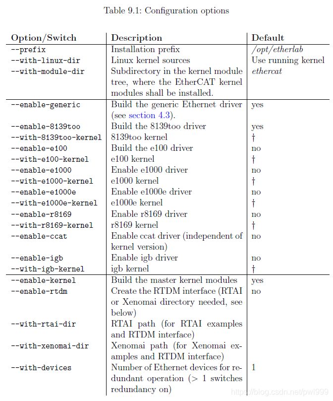
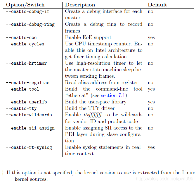
1.9.3 Building the Interface Documentation
The source code is documented using Doxygen [13]. To build the HTML documentation, the Doxygen software has to be installed. The below command will generate the documents in the subdirectory doxygen-output:
// 使用Doxygen [13]记录了源代码。 要生成HTML文档,必须安装Doxygen软件。 以下命令将在子目录doxygen-output中生成文档:
$ make doc
The interface documentation can be viewed by pointing a browser to the file doxygen-output/html/index.html. The functions and data structures of the application interface a covered by an own module “Application Interface”.
// 可以通过将浏览器指向文件doxygen-output / html / index.html来查看接口文档。 应用程序接口的功能和数据结构由自己的模块“应用程序接口”覆盖。
1.9.4 Installing the Software
The below commands have to be entered as root: The first one will install the EtherCAT header, init script, sysconfig file and the userspace tool to the prefix path. The second one will install the kernel modules to the kernel’s modules directory. The final depmod call is necessary to include the kernel modules into the modules.dep file to make it available to the modprobe command, used in the init script.
// 必须以root用户身份输入以下命令:第一个命令将EtherCAT标头,初始化脚本,sysconfig文件和用户空间工具安装到前缀路径。第二个将内核模块安装到内核的modules目录。最后的depmod调用对于将内核模块包括到modules.dep文件中是必需的,以使其可用于init脚本中的modprobe命令。
# make install
# make modules install
If the target kernel’s modules directory is not under /lib/modules, a different destination directory can be specified with the DESTDIR make variable. For example:
// 如果目标内核的模块目录不在/lib/modules下,则可以使用DESTDIR make变量指定其他目标目录。例如:
# make DESTDIR=/vol/nfs/root modules install
This command will install the compiled kernel modules to /vol/nfs/root/lib/modules, prepended by the kernel release.
// 该命令会将已编译的内核模块安装到内核发行版之前的/vol/nfs/root/lib/modules中。
If the EtherCAT master shall be run as a service4 (see section 7.4), the init script and the sysconfig file (or the systemd service file, respectively) have to be copied (or linked) to the appropriate locations. The below example is suitable for SUSE Linux. It may vary for other distributions.
// 如果EtherCAT主站应作为service运行(请参见7.4节),则必须将init脚本和sysconfig文件(或分别为systemd服务文件)复制(或链接)到适当的位置。以下示例适用于SUSE Linux。对于其他发行版,它可能有所不同。
# cd /opt/etherlab
# cp etc/sysconfig/ethercat /etc/sysconfig/
# ln -s etc/init.d/ethercat /etc/init.d/
# insserv ethercat
Now the sysconfig file /etc/sysconfig/ethercat (see subsection 7.4.2), or the configuration file /etc/ethercat.conf, if using systemd, has to be customized. The minimal customization is to set the MASTER0_DEVICE variable to the MAC address of the Ethernet device to use (or ff:ff:ff:ff:ff:ff to use the first device offered) and selecting the driver(s) to load via the DEVICE_MODULES variable.
// 现在,必须自定义sysconfig文件/ etc / sysconfig / ethercat(请参见7.4.2小节),或配置文件/etc/ethercat.conf(如果使用systemd)。最小的自定义方法是将MASTER0_DEVICE变量设置为要使用的以太网设备的MAC地址(或使用提供的第一个设备使用ff:ff:ff:ff:ff:ff),然后选择要通过驱动程序加载的驱动程序。 DEVICE_MODULES变量。
After the basic configuration is done, the master can be started with the below command:
// 完成基本配置后,可以使用以下命令启动主服务器:
# /etc/init.d/ethercat start
When using systemd, the following command can be used alternatively:
// 使用systemd时,可以交替使用以下命令:
# ethercatctl start
At this time, the operation of the master can be observed by viewing the Syslog messages, which should look like the ones below. If EtherCAT slaves are connected to the master’s EtherCAT device, the activity indicators should begin to flash.
// 这时,可以通过查看Syslog消息来观察主服务器的操作,该消息应如下所示。如果将EtherCAT从站连接到主站的EtherCAT设备,则活动指示灯应开始闪烁。
1 EtherCAT : Master driver 1.5.2
2 EtherCAT : 1 master waiting for devices .
3 EtherCAT Intel (R) PRO /1000 Network Driver - version 6.0.60 - k2
4 Copyright (c) 1999 -2005 Intel Corporation .
5 PCI : Found IRQ 12 for device 0000:01:01.0
6 PCI : Sharing IRQ 12 with 0000:00:1 d.2
7 PCI : Sharing IRQ 12 with 0000:00:1 f.1
8 EtherCAT : Accepting device 00:0 E:0C:DA:A2 :20 for master 0.
9 EtherCAT : Starting master thread .
10 ec_e1000 : ec0: e1000_probe : Intel (R) PRO /1000 Network
11 Connection
12 ec_e1000 : ec0: e1000_watchdog_task : NIC Link is Up 100 Mbps
13 Full Duplex
14 EtherCAT : Link state changed to UP.
15 EtherCAT : 7 slave (s) responding .
16 EtherCAT : Slave states : PREOP .
17 EtherCAT : Scanning bus.
18 EtherCAT : Bus scanning completed in 431 ms.

# 1 - 2 The master module is loading, and one master is initialized.

# 3 - 8 The EtherCAT-capable e1000 driver is loading. The master accepts the device with the address 00:0E:0C:DA:A2:20.

# 9 - 16 The master goes to idle phase, starts its state machine and begins scanning the bus.
1.9.5 Automatic Device Node Creation
The ethercat command-line tool (see section 7.1) communicates with the master via a character device. The corresponding device nodes are created automatically, if the udev daemon is running. Note, that on some distributions, the udev package is not installed by default.
// ethercat命令行工具(请参阅第7.1节)通过字符设备与主机通信。如果udev守护程序正在运行,则会自动创建相应的设备节点。请注意,在某些发行版中,默认情况下未安装udev软件包。
The device nodes will be created with mode 0660 and group root by default. If “normal” users shall have reading access, a udev rule le (for example /etc/udev/rules.d/99-EtherCAT.rules) has to be created with the following contents:
// 默认情况下,将使用模式0660和组root创建设备节点。如果“普通”用户具有阅读权限,则必须创建具有以下内容的udev规则文件(例如/etc/udev/rules.d/99-EtherCAT.rules):
KERNEL ==" EtherCAT [0 -9]*" , MODE ="0664"
After the udev rule file is created and the EtherCAT master is restarted with /etc/init.d/ethercat restart, the device node will be automatically created with the desired rights:
// 创建udev规则文件并使用/etc/init.d/ethercat restart重新启动EtherCAT主站之后,将自动以所需的权限创建设备节点:
# ls -l /dev/EtherCAT0
crw -rw -r-- 1 root root 252 , 0 2008 -09 -03 16:19 /dev / EtherCAT0
Now, the ethercat tool can be used (see section 7.1) even as a non-root user. If non-root users shall have writing access, the following udev rule can be used instead:
// 现在,即使是非root用户也可以使用ethercat工具(请参阅7.1节)。如果非root用户具有写访问权,则可以使用以下udev规则代替:
KERNEL ==" EtherCAT [0 -9]*" , MODE ="0664" , GROUP =" users "
2. 实践分析
2.1 fsm_master状态机
fsm_master结构体:
struct ec_fsm_master {
    ec_master_t *master; /**< master the FSM runs on */
    ec_datagram_t *datagram; /**< datagram used in the state machine */
    unsigned int retries; /**< retries on datagram timeout. */

    void (*state)(ec_fsm_master_t *); /**< master state function */
    ec_device_index_t dev_idx; /**< Current device index (for scanning etc.).
                            */
    int idle; /**< state machine is in idle phase */
    unsigned long scan_jiffies; /**< beginning of slave scanning */
    uint8_t link_state[EC_MAX_NUM_DEVICES]; /**< Last link state for every
                                          device. */
    unsigned int slaves_responding[EC_MAX_NUM_DEVICES]; /**< Number of
                                                      responding slaves
                                                      for every device. */
    unsigned int rescan_required; /**< A bus rescan is required. */
    ec_slave_state_t slave_states[EC_MAX_NUM_DEVICES]; /**< AL states of
                                                     responding slaves for
                                                     every device. */
    ec_slave_t *slave; /**< current slave */
    ec_sii_write_request_t *sii_request; /**< SII write request */
    off_t sii_index; /**< index to SII write request data */
    ec_sdo_request_t *sdo_request; /**< SDO request to process. */

    ec_fsm_coe_t fsm_coe; /**< CoE state machine */
    ec_fsm_soe_t fsm_soe; /**< SoE state machine */
    ec_fsm_pdo_t fsm_pdo; /**< PDO configuration state machine. */
    ec_fsm_change_t fsm_change; /**< State change state machine */
    ec_fsm_slave_config_t fsm_slave_config; /**< slave state machine */
    ec_fsm_slave_scan_t fsm_slave_scan; /**< slave state machine */
    ec_fsm_sii_t fsm_sii; /**< SII state machine */
};
以IDLE为例,状态机周期调用关系如下图所示:
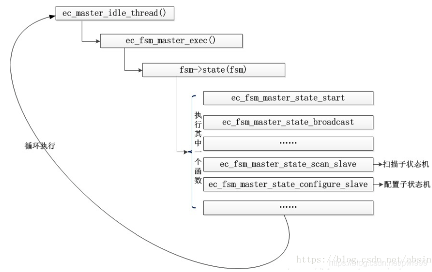
其中ec_master_idle_thread()的调用周期与系统滴答时间有关:
//send interval in IDLE phase
ec_master_set_send_interval(master, 1000000/HZ);
2.2 初始化流程
源代码执行命令sudo /etc/init.d/ethercat start,将会从文件module.c文件中的ec_init_module函数中开始往下执行初始化流程。
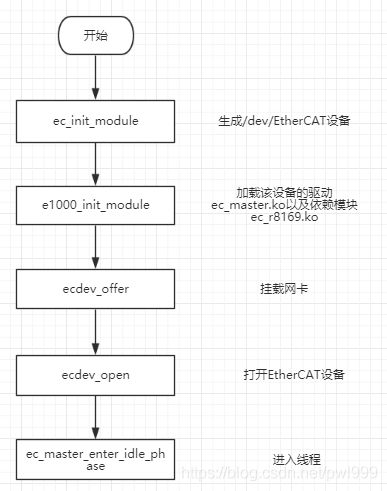
- ec_init_module
主要用于生成/dev/EtherCAT设备,并且调用ec_master_init初始化主机相关信息。
ec_master_init()的主要工作内容:
1.设置IDLE模式下数据发送周期;
2.初始化数据包队列;
3.初始化网络设备;
4.初始化master主状态机;
5.初始化参考时钟数据包;
6.初始化时钟数据包;
7.初始化对时监测数据包;
8.初始化字符设备,/dev/EtherCAT0;
9.初始化RTDM设备;
- IDLE状态进程
设备打开后,设备调用ec_master_enter_idle_phase,该函数中将启用ec_master_idle_thread进程
ec_master_idle_thread以设定的周期(send_interval)发送数据包并处理,其流程如下:
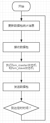
2.3 程序框架
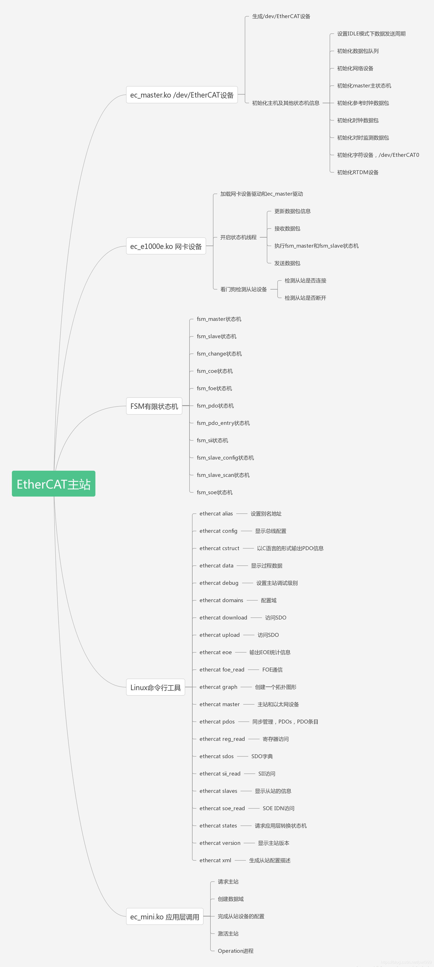
3. 测试
3.1 实时性测试
在DC同步模式下,Ethercat主站能否在规定的时间内发送过程数据帧,是影响整个系统性能的关键因素,本文介绍如何使用Wireshark抓取总线上的Ethercat数据包,并将主站发过程数据帧的时间间隔以曲线的形式显示出来。
- 连接ET2000
将ET2000串接在网络中:

- 启用ESL协议
打开Wireshark -> 分析 ->启用的协议对话框,勾选esl_eth:
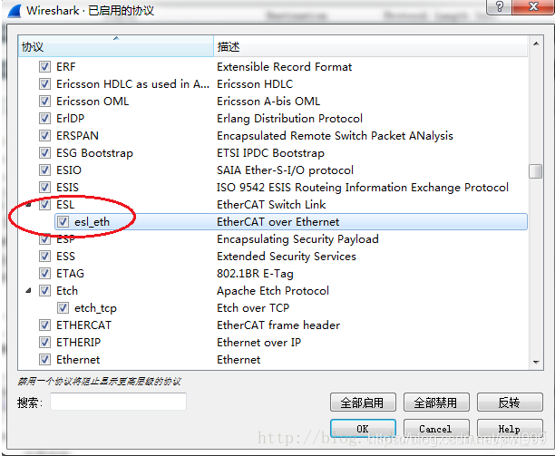
- 抓取数据
抓取的数据如下,其中EtherCAT Switch Link下的timestamp是ET2000添加到数据包末尾的时间戳,单位为ns。而Time下的时间为运行Wireshark的Windows系统添加的时间戳。
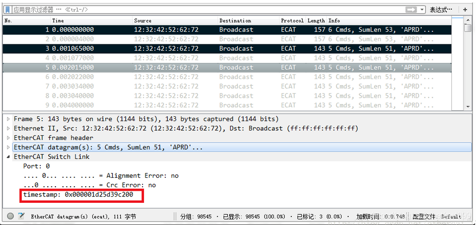
- 筛选数据
由于只分析主站发送数据的时间,即working counter 为0的数据,使用过滤规则
(eth.type == 0x88a4) && (ecat.cnt == 0)
过滤数据,并导出为另一个文件,例如导出到D:\test.pcap
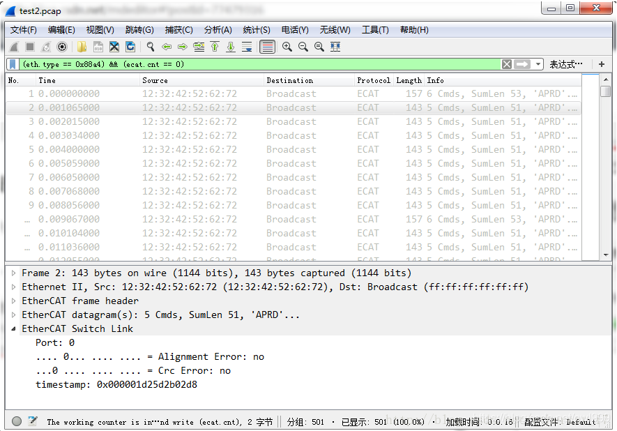
- 使用tshark导出时间戳
使用tshark命令将ET2000的时间戳导出为csv文件:
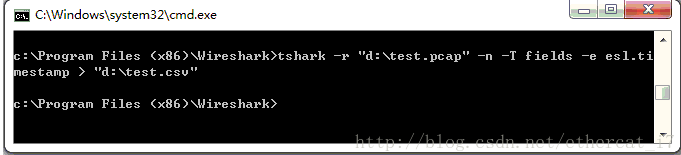
导出结果为:

- 绘图
将csv中的发送时间间隔绘制成曲线图,可看出该主站的时间抖动在60us左右:

作为对比,Windows的时间戳抖动达到200us。
可见,ET2000的时间戳才能反映真实的主站实时性。
- 性能分析
采用WireShark中的高级功能IO Graphs,对采集到的实验室现场数据报文,进行综合的数据统计和分析:
[外链图片转存失败,源站可能有防盗链机制,建议将图片保存下来直接上传(img-vUZmwHZM-1604106304843)(imge/profinet/wireshark_io_graphs.PNG)]
3.2 一致性测试
在EtherCAT从站开发过程中,使用ETG官方提供的一致性测试软件对产品进行一致性测试是非常有必要的。
- 获取软件
EtherCAT Conformance Test Tool,简称CTT,需要以ETG会员的身份进行购买,订货信息为ET9400,每次购买的有效期为一年,过期后需重新购买。
ETG官网上关于CTT的介绍: https://www.ethercat.org.cn/cn/products/2b8481d0918740ae91af0aece1ff8c2f.htm
- 一致性测试
购买CTT并安装后,就可以对从站进行一致性测试了。
首先,把从站的设备描述文件(xml)拷贝到CTT安装目录对应的文件夹下:
C:\Program Files (x86)\EtherCAT Conformance Test\DeviceDescriptions
打开CTT软件,新建工程后,右键点击EtherCAT Devices添加设备:

如果检测到从站,ECAT Link将显示为True:
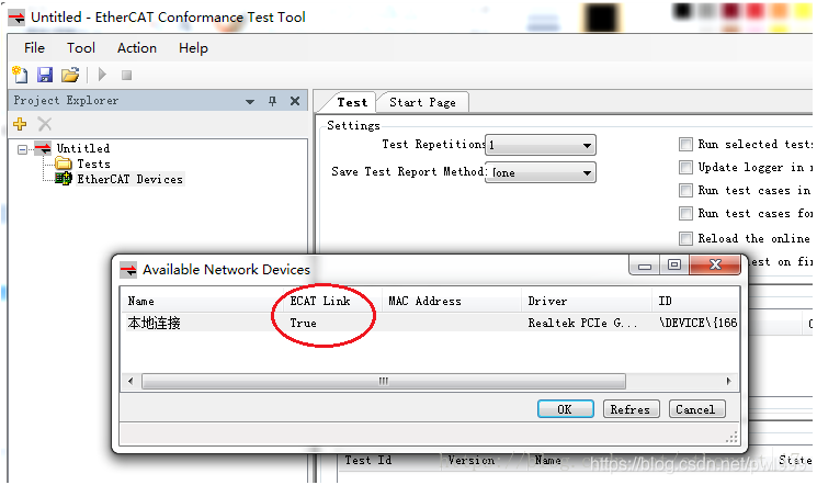
点击OK后将显示检测到的从站,右键点击Tests下的EtherCAT标签,添加默认测试案例:
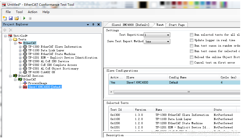
点击工具栏中绿色三角图标即开始测试,测试完成后将生成测试报告,对于不通过项会显示红色,可根据提示对从站代码或设备描述文件进行修改。
测试完成后的结果如下:

- 测试内容简介
CTT将测试案例分成几大类,分别以TF-XXXX命名,展开后可看到各大类下的测试案例:
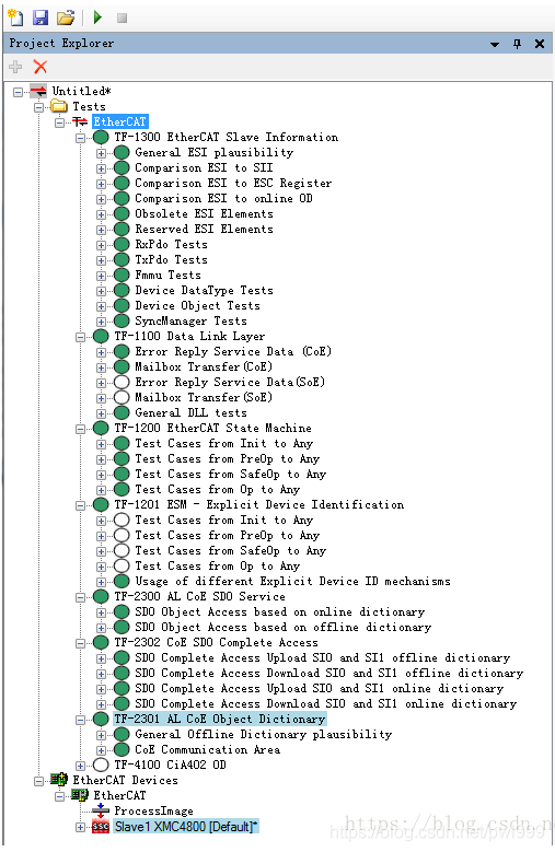
测试案例简要分析:
(1) TF-1300 EtherCAT Slave Information
主要测试设备描述文件(xml)中的内容是否与从站EERPOM中的内容一致,包括Vendor ID, PDO配置,FMMU配置,以及数据字典等等。

(2) TF-1100 Data Link Layer
主要测试邮箱通信。

(3) TF-1200 EtherCAT State Machine
主要测试状态机,init, preop, safeop, op这些状态的互相跳转是否正常。

(4) TF-1201 Explicit Device Identification
特殊ID设备的测试,被跳过。

(5) TF-2300 AL CoE SDO service
测试数据字典在不同总线状态下的读写是否正确。

(6) TF-2302 CoE SDO Complete Access
如果从站声明支持Complete Access功能,将对该功能进行测试。

(7) TF-2301 AL CoE Object Dictionary
测试从站离线和在线数据字典是否一致。

(8) TF-4100 CiA402 OD
测试CiA402相关数据字典,本测试案例中从站不是CiA402设备,所以相关测试被忽略。
- 一致性认证
通过一致性测试后,就可以到ETG相关机构申请一致性认证,除了CTT相关测试内容,一致性认证还包括从站设备的指示灯是否规范,与其它产品的兼容性等。通过后就可以拿到一致性认证的证书,并在产品上贴上一致性认证标签。

4. igh移植
4.1 xenomai移植
1、ipipe补丁:
tar -xvf linux-4.4.182.tar.xz
cd linux-4.4.182/
patch -p1 < ../ipipe-core-4.4.182-x86-15.patch
2、xenomai补丁:
tar -xvf xenomai-3.0.10.tar.bz2
cd xenomai-3.0.10
./scripts/prepare-kernel.sh --linux=/home/myc/vx/igh/linux-4.4.182 --arch=x86_64 --outpatch=../xenomai-3.0.10.patch

cd linux-4.4.182/
patch -p1 < ../xenomai-3.0.10.patch
3、编译内核
cd linux-4.4.182/
cp /boot/config-4.4.0-176-generic .config
make menuconfig

make bzImage -j4
make modules -j4
4、安装
安装模块:
make INSTALL_MOD_STRIP=1 modules_install
安装ramfa和内核:
sudo mkinitramfs /lib/modules/4.4.182+/ -o /boot/initrd.img-4.4.182-xenomai
sudo cp arch/x86/boot/bzImage /boot/vmlinuz-4.4.182-xenomai
sudo cp System.map /boot/System.map-4.4.182-xenomai
sudo update-grub2
5、安装应用程序:
cd xenomai-3.0.10
./configure --with-core=cobalt --enable-smp --enable-pshared
./configure --with-core=cobalt --enable-smp --enable-pshared  CFLAGS="-fPIC"
sudo make install
6、测试:
myc@myc-virtual-machine:~$ dmesg | grep -i xenomai
[    0.000000] Command line: BOOT_IMAGE=/boot/vmlinuz-4.4.182-xenomai root=UUID=bdc34999-c918-4a67-a92d-9bd7732e3820 ro quiet splash
[    0.000000] Kernel command line: BOOT_IMAGE=/boot/vmlinuz-4.4.182-xenomai root=UUID=bdc34999-c918-4a67-a92d-9bd7732e3820 ro quiet splash
[    2.674918] [Xenomai] scheduling class idle registered.
[    2.674919] [Xenomai] scheduling class rt registered.
[    2.699489] I-pipe: head domain Xenomai registered.
[    2.738189] [Xenomai] Cobalt v3.0.10
$ sudo /usr/xenomai/bin/latency
== Sampling period: 100 us
== Test mode: periodic user-mode task
== All results in microseconds
warming up...
RTT|  00:00:15  (periodic user-mode task, 100 us period, priority 99)
RTH|----lat min|----lat avg|----lat max|-overrun|---msw|---lat best|--lat worst
RTD|      3.443|    730.867|  19528.564|   67967|     0|      3.443|  19528.564
RTD|      2.027|    729.319|  46168.093|  135725|     0|      2.027|  46168.093
RTD|      1.948|    580.795|  33114.187|  188888|     0|      1.948|  46168.093
RTD|      1.492|    379.718|  28321.906|  221916|     0|      1.492|  46168.093
RTD|      4.358|    431.370|  27549.434|  260074|     0|      1.492|  46168.093
RTD|      2.397|    729.442|  26226.420|  327974|     0|      1.492|  46168.093
RTD|      3.094|    382.390|  27201.676|  361266|     0|      1.492|  46168.093
RTD|      2.892|    381.338|  35848.720|  394314|     0|      1.492|  46168.093
^C---|-----------|-----------|-----------|--------|------|-------------------------
4.2 igh移植
1、配置
# 原生版本igh
unzip ethercat-master.zip
cd ethercat-master/

# intel xenomai 版本
unzip xenomai-ethercat-master.zip
cd xenomai-ethercat-master

./configure --with-linux-dir=/home/myc/vx/igh/linux-4.4.182 --with-module-dir=/lib/modules/4.4.182+/ --enable-generic --enable-rtdm --with-xenomai-dir=/usr/xenomai --enable-cycles --enable-hrtimer --enable-8139too=no
2、编译
make
make modules
libtool问题:
autoreconf -ivf
3、安装:
sudo make install
sudo make modules_install
4、systemd配置:
创建ethercat.service文件:
sudo vim /usr/lib/systemd/user/ethercat.service
ethercat.service文件内容:
#
# EtherCAT master kernel modules
#
[ Unit ]
Description = EtherCAT Master Kernel Modules
#
# Uncomment this , if the generic Ethernet driver is used . It assures , that the
# network interfaces are configured , before the master starts .
#
# Requires = network . service # Stop master , if network is stopped
# After = network . service # Start master , after network is ready
#
# Uncomment this , if a native Ethernet driver is used . It assures , that the
# network interfaces are configured , after the Ethernet drivers have been
# replaced . Otherwise , the networking configuration tools could be confused .
#
# Before = network.service
[ Service ]
Type = oneshot
RemainAfterExit = yes
ExecStart = /opt/etherlab/sbin/ethercatctl start
ExecStop = /opt/etherlab/sbin/ethercatctl stop

[ Install ]
WantedBy = multi-user.target
拷贝配置文件并编辑:
sudo cp /opt/etherlab/etc/ethercat.conf /etc/
sudo vim /etc/ethercat.conf
ethercat.conf文件内容:
MASTER0_DEVICE="00:0c:29:74:35:3b"

DEVICE_MODULES="generic"
启动ethercat service:
systemctl restart ethercat
5、用户态命令行测试:
sudo /opt/etherlab/bin/ethercat config