二、DAC,数字模拟转换
1、定义
STM32F4 的 DAC 模块(数字/模拟转换模块)是 12 位数字输入,电压输出型的 DAC。DAC可以配置为 8 位或 12位模式,也可以与 DMA 控制器配合使用。 DAC 工作在 12 位模式时,数据可以设置成左对齐或右对齐,一般设置右对齐,从第零位开始。 DAC 模块有 2个输出通道,每个通道都有单独的转换器。在双 DAC 模式下, 2 个通道可以独立地进行转换,也可以同时进行转换并同步地更新 2个通道的输出。 DAC 可以通过引脚输入参考电压 Vref+(通 ADC 共用) 以获得更精确的转换结果。
#主要应用在
输出自定义电压、音频播放、视频播放
2、库函数
a.根据DAC_InitTypeDef初始化DAC
- @param DAC_Channel: the selected DAC channel.
- This parameter can be one of the following values:
-
@arg DAC_Channel_1: DAC Channel1 selected -
@arg DAC_Channel_2: DAC Channel2 selected - @param DAC_InitStruct: pointer to a DAC_InitTypeDef structure that contains the configuration information for the specified DAC channel.
void DAC_Init(uint32_t DAC_Channel, DAC_InitTypeDef* DAC_InitStruct)
typedef struct
{


  uint32_t DAC_Trigger;                      /*!< Specifies the external trigger for the selected DAC channel.
                                                  This parameter can be a value of @ref DAC_trigger_selection */

  uint32_t DAC_WaveGeneration;               /*!< Specifies whether DAC channel noise waves or triangle waves
                                                  are generated, or whether no wave is generated.
                                                  This parameter can be a value of @ref DAC_wave_generation */

  uint32_t DAC_LFSRUnmask_TriangleAmplitude; /*!< Specifies the LFSR mask for noise wave generation or
                                                  the maximum amplitude triangle generation for the DAC channel.
                                                  This parameter can be a value of @ref DAC_lfsrunmask_triangleamplitude */

  uint32_t DAC_OutputBuffer;                 /*!< Specifies whether the DAC channel output buffer is enabled or disabled.
                                                  This parameter can be a value of @ref DAC_output_buffer */
}DAC_InitTypeDef;
b.使能 DAC 对应的通道
- @param DAC_Channel: The selected DAC channel.
- This parameter can be one of the following values:
-
@arg DAC_Channel_1: DAC Channel1 selected -
@arg DAC_Channel_2: DAC Channel2 selected - @param NewState: new state of the DAC channel.
-
This parameter can be: ENABLE or DISABLE. - @note When the DAC channel is enabled the trigger source can no more be modified.
void DAC_Cmd(uint32_t DAC_Channel, FunctionalState NewState)
c.设置DAC对应通道的数据对齐格式,输出数据值
- @brief Set the specified data holding register value for DAC channel1.
- @param DAC_Align: Specifies the data alignment for DAC channel1.
- This parameter can be one of the following values:
-
@arg DAC_Align_8b_R: 8bit right data alignment selected -
@arg DAC_Align_12b_L: 12bit left data alignment selected -
@arg DAC_Align_12b_R: 12bit right data alignment selected - @param Data: Data to be loaded in the selected data holding register.
void DAC_SetChannel1Data(uint32_t DAC_Align, uint16_t Data)
软件设置输出电压的计算公式如下:
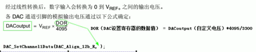
实现每1Sdac的值自动加100,超过3300置为0,重新计数。
部分代码:
void dac_init(void)
{


	/* GPIOA clock enable (to be used with DAC) ,GPIOA硬件时钟初始化*/
	RCC_AHB1PeriphClockCmd(RCC_AHB1Periph_GPIOA, ENABLE);

	/* DAC Periph clock enable ,DAC硬件时钟使能*/
	RCC_APB1PeriphClockCmd(RCC_APB1Periph_DAC, ENABLE);


	/* 配置DAC1为模拟输入引脚 */
	GPIO_InitStructure.GPIO_Pin = GPIO_Pin_4;				//第4号引脚
	GPIO_InitStructure.GPIO_Mode = GPIO_Mode_AN;			//引脚设置为模拟输出,能够输出更加广范围的电平(0V~3.3V任何电压)
	GPIO_InitStructure.GPIO_PuPd = GPIO_PuPd_NOPULL ;
	GPIO_Init(GPIOA, &GPIO_InitStructure);

	/* DAC channel1 Configuration ,DAC通道1配置*/
	DAC_InitStructure.DAC_Trigger = DAC_Trigger_None;						//不依赖于其他定时器来触发DAC硬件的输出,通过软件触发输出电压值
	DAC_InitStructure.DAC_WaveGeneration = DAC_WaveGeneration_None;			//不需要输出波形,只需要输出自定义的电压值
	DAC_InitStructure.DAC_OutputBuffer = DAC_OutputBuffer_Enable;			//使能输出
	DAC_Init(DAC_Channel_1, &DAC_InitStructure);

	/* Enable DAC Channel1,使能DAC通道1硬件 */
	DAC_Cmd(DAC_Channel_1, ENABLE);


}

int main(void)
{


	uint32_t adc_val,adc_vol;
	uint32_t dac_vol=0;			//自定义电压值

	LED_Init();

	//系统定时器初始化,时钟源来自HCLK,且进行8分频,
	//系统定时器时钟频率=168MHz/8=21MHz
	SysTick_CLKSourceConfig(SysTick_CLKSource_HCLK_Div8);

	//设置中断优先级分组2
	NVIC_PriorityGroupConfig(NVIC_PriorityGroup_2);

	//串口1,波特率115200bps,开启接收中断
	USART1_Init(115200);

	//DAC初始化
	dac_init();

	//ADC初始化
	adc_init();


	while(1)
	{


		dac_vol +=100;

		//使用DAC通道1输出自定义电压值
		DAC_SetChannel1Data(DAC_Align_12b_R, dac_vol*4095/3300);

		printf("dac vol=%dmv\r\n",dac_vol);

		if(dac_vol >=3300)
			dac_vol = 0;

		delay_ms(500);


		/* Start ADC Software Conversion ,启动ADC1进行转换*/
		ADC_SoftwareStartConv(ADC1);

		//等待转换结束
		while(ADC_GetFlagStatus(ADC1,ADC_FLAG_EOC)==RESET);


		//获取ADC转换后的数值
		adc_val=ADC_GetConversionValue(ADC1);

		//将ADC输出的结果值转换位电压值
		adc_vol = adc_val*3300/4095;

		printf("adc vol = %dmv\r\n",adc_vol);

		delay_ms(500);

	}
}