实验要求:
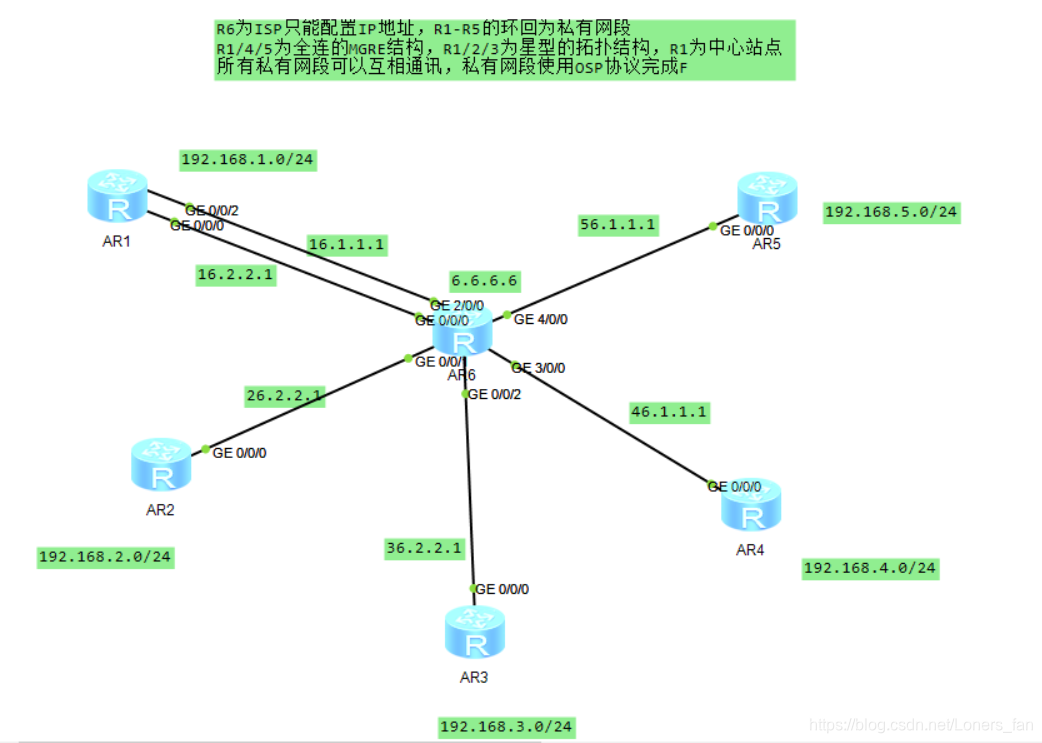
- R6为ISP只能配置IP地址,R1-R5的环回为私有网段
- R1/4/5为全连的MGRE结构;
- R1/2/3为星型的拓扑结构,R1为中心站点
- 所有私有网段可以互相通讯,私有网段使用OSPF协议完成
实验拓扑
实验配置及思路
1、规划IP,并给所有路由器均配置一个环回接口;
首先把公网部分搞通,给各个路由器配ip,并且给除了R6(ISP)外的其他路由写缺省路由,指向R6;
结果如图:
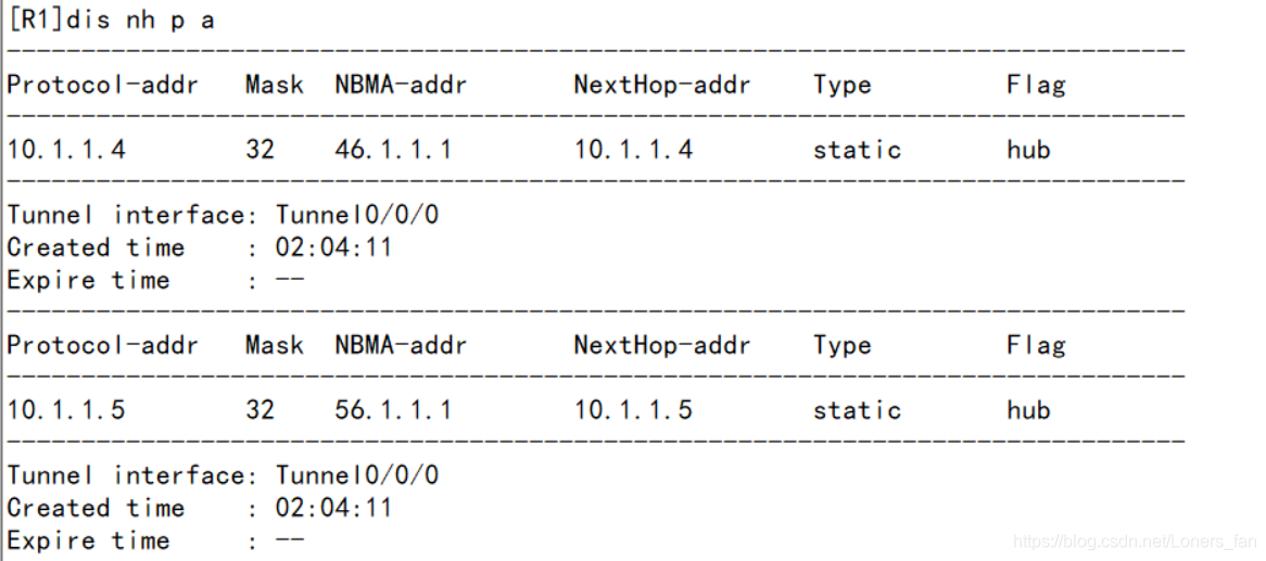
2、构建R1/4/5为全连的MGRE结构,题目要求全连,R1/R4/R5需要互相注册;
在MGRE环境下,OSPF的默认工作方式为点到点,只能建立一个邻居,所以需要修改各个路由器的tunnel接口模式为broadcast;
R1:
 interface Tunnel0/0/0
 ip address 10.1.1.1 255.255.255.0
 tunnel-protocol gre p2mp
 source 16.1.1.1
 ospf network-type broadcast
 nhrp entry multicast dynamic
 nhrp network-id 100
 nhrp entry 10.1.1.4 46.1.1.1 register
 nhrp entry 10.1.1.5 56.1.1.1 register
R4:
 interface Tunnel0/0/0
 ip address 10.1.1.4 255.255.255.0
 tunnel-protocol gre p2mp
 source 46.1.1.1
 ospf network-type broadcast
 nhrp entry multicast dynamic
 nhrp network-id 100
 nhrp entry 10.1.1.1 16.1.1.1 register
 nhrp entry 10.1.1.5 56.1.1.1 register
R5:
 interface Tunnel0/0/0
 ip address 10.1.1.5 255.255.255.0
 tunnel-protocol gre p2mp
 source 56.1.1.1
 ospf network-type broadcast
 nhrp entry multicast dynamic
 nhrp network-id 100
 nhrp entry 10.1.1.1 16.1.1.1 register
 nhrp entry 10.1.1.4 46.1.1.1 register
结果如下表
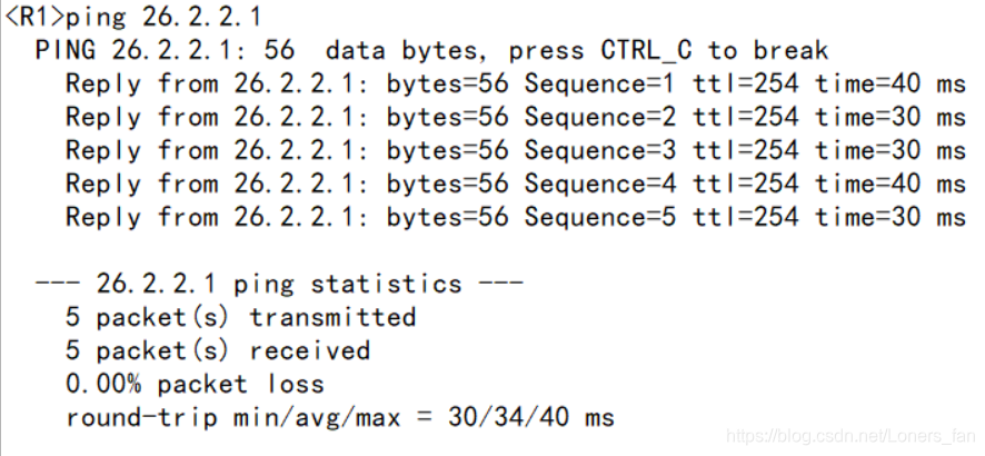
3、R1/2/3为星型的拓扑结构,R1为中心站点,R2/R3需要到R1注册,同样要切换接口工作方式为broadcast;
在星型结构的MGRE结构下,可能会出现DR位置错误,所以为了避免这种情况的发生,把R2/R3中的tunnel接口优先级改为0,让他们不参与选举,就可以干扰DR为R1;
R1:
 interface Tunnel0/0/1
 ip address 10.1.2.1 255.255.255.0
 tunnel-protocol gre p2mp
 source 16.2.2.1
 ospf network-type broadcast
 nhrp entry multicast dynamic
 nhrp network-id 101
R2:
 interface Tunnel0/0/1
 ip address 10.1.2.2 255.255.255.0
 tunnel-protocol gre p2mp
 source 26.2.2.1
 ospf network-type broadcast
 ospf dr-priority 0
 nhrp network-id 101
 nhrp entry 10.1.2.1 16.2.2.1 register
R3:
 interface Tunnel0/0/1
 ip address 10.1.2.3 255.255.255.0
 tunnel-protocol gre p2mp
 source 36.2.2.1
 ospf network-type broadcast
 ospf dr-priority 0
 nhrp network-id 101
 nhrp entry 10.1.2.1 16.2.2.1 register
结果如图所示: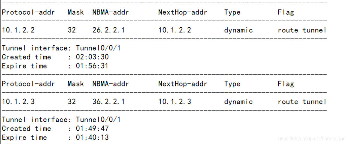
4、保证畅通的情况下,给路由起OSPF协议
R1:
 ospf 1 router-id 1.1.1.1
 area 0.0.0.0
 network 10.1.1.1 0.0.0.0
 network 10.1.2.1 0.0.0.0
 network 192.168.1.0 0.0.0.255
R2:
 ospf 1 router-id 2.2.2.2
 area 0.0.0.0
 network 10.1.2.2 0.0.0.0
 network 192.168.2.1 0.0.0.0
R3:
 ospf 1 router-id 3.3.3.3
 area 0.0.0.0
 network 10.1.2.3 0.0.0.0
 network 192.168.3.1 0.0.0.0
R4:
 ospf 1 router-id 4.4.4.4
 area 0.0.0.0
 network 10.1.1.4 0.0.0.0
 network 192.168.4.1 0.0.0.0
R5:
 ospf 1 router-id 5.5.5.5
 area 0.0.0.0
 network 10.1.1.5 0.0.0.0
 network 192.168.5.1 0.0.0.0
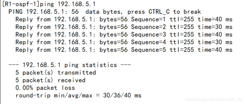
结果如下图所示:
5、想要访问R6的环回,需要抓取流量,在访问公网时将私有IP转化为公有IP;
R1:
 acl 2000
 rule 5 permit source 192.168.1.0 0.0.0.255
 interface GigabitEthernet0/0/2
 nat outbound 2000
 interface GigabitEthernet0/0/0
 nat outbound 2000
其他路由器同理;
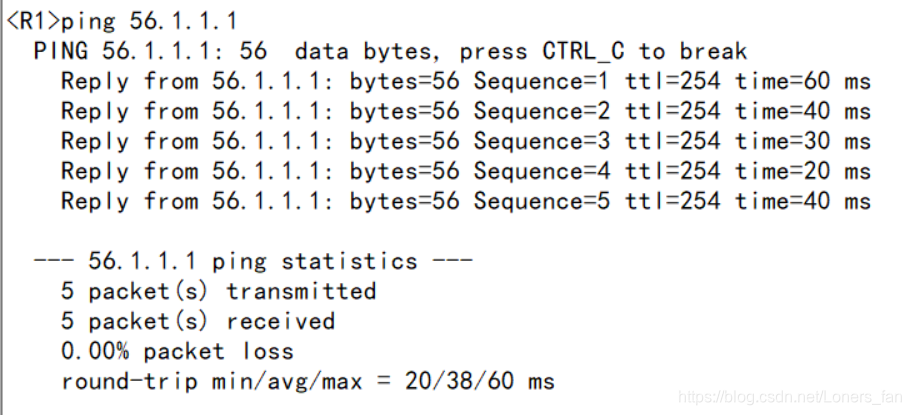
6、测试
结果如图所示:
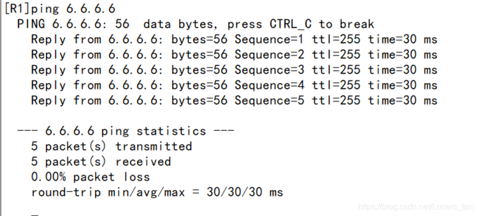
实验目标达成,实验结束