华为——策略路由(校园网配置)
作用:通过分析数据报的源地址和目标地址,按照策略规则选择不同的网关,进行数据转发。提供冗余,负载,但是还是单线路的速度。只是提供了不同的方向,并没有进行合并线路。
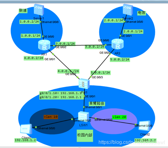
拓扑图如下:
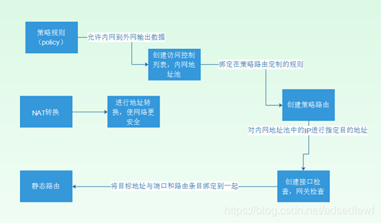
配置思路:
配置命令:
1.LSW1配置:
[Huawei]vlan 10
[Huawei-vlan10]vlan 20
[Huawei-vlan20]quit
[Huawei]int e0/0/2
[Huawei-GigabitEthernet0/0/2]port link-type access
[Huawei]int e0/0/3
[Huawei-Ethernet0/0/3]port link-type access //将接口类型定义为接入模式
[Huawei-Ethernet0/0/3]port default vlan 20 //将接口划分vlan 20
[Huawei]int e0/0/1
[Huawei-Ethernet0/0/1]port link-type trunk //将该接口定义为Trunk中继模式
[Huawei-Ethernet0/0/1]port trunk allow-pass vlan all //允许所有vlan通过
2.AR1配置:
sys
Enter system view, return user view with Ctrl+Z.
[Huawei]int g0/0/0
[Huawei-GigabitEthernet0/0/0]ip add 1.0.0.1 255.255.255.0
[Huawei-GigabitEthernet0/0/0]undo shutdown
[Huawei-GigabitEthernet0/0/0]quit
[Huawei]int g0/0/1
[Huawei-GigabitEthernet0/0/1]ip add 4.0.0.2 255.255.255.0
[Huawei-GigabitEthernet0/0/1]undo shutdown
[Huawei]int g0/0/2
[Huawei-GigabitEthernet0/0/2]ip add 3.0.0.1 255.255.255.0
[Huawei-GigabitEthernet0/0/2]undo shutdown
[Huawei-GigabitEthernet0/0/2]quit
配置OSPF,定义为area 0区域
[Huawei]ospf 1
[Huawei-ospf-1]area 0
[Huawei-ospf-1-area-0.0.0.0]network 1.0.0.0 0.0.0.255
[Huawei-ospf-1-area-0.0.0.0]network 3.0.0.0 0.0.0.255
[Huawei-ospf-1-area-0.0.0.0]network 4.0.0.0 0.0.0.255
- AR3配置:
sys
Enter system view, return user view with Ctrl+Z.
[Huawei]undo info-center enable //关闭consolo端接入设备信息中心发送的 调试/报警/日志消息
Info: Information center is disabled.
[Huawei]int g0/0/0
[Huawei-GigabitEthernet0/0/0]ip add 3.0.0.2 255.255.255.0
[Huawei-GigabitEthernet0/0/0]undo shutdown
[Huawei-GigabitEthernet0/0/0]quit
[Huawei]int g0/0/1
[Huawei-GigabitEthernet0/0/1]ip add 2.0.0.1 255.255.255.0
[Huawei-GigabitEthernet0/0/1]undo shutdown
[Huawei-GigabitEthernet0/0/1]quit
[Huawei]int g0/0/2
[Huawei-GigabitEthernet0/0/2]ip add 5.0.0.2 255.255.255.0
[Huawei-GigabitEthernet0/0/2]undo shutdown
[Huawei-GigabitEthernet0/0/2]quit
配置OSPF,定义区域为area 0
[Huawei]ospf 1
[Huawei-ospf-1]area 0
[Huawei-ospf-1-area-0.0.0.0]network 3.0.0.0 0.0.0.255
[Huawei-ospf-1-area-0.0.0.0]network 5.0.0.0 0.0.0.255
[Huawei-ospf-1-area-0.0.0.0]network 2.0.0.0 0.0.0.255
[Huawei-ospf-1-area-0.0.0.0]quit
4.(USG5500)FW1配置:
SYS
11:46:33 2020/03/03
Enter system view, return user view with Ctrl+Z.
[SRG]undo info-center enable //关闭consolo端接入设备信息中心发送的 调试/报警/日志消息
[SRG]int g0/0/2
[SRG-GigabitEthernet0/0/2]ip add 4.0.0.1 255.255.255.0
[SRG-GigabitEthernet0/0/2]undo shutdown
[SRG]int g0/0/3
[SRG-GigabitEthernet0/0/3]ip add 5.0.0.1 255.255.255.0
[SRG-GigabitEthernet0/0/3]undo shutdown
[SRG]int g0/0/1.10
[SRG-GigabitEthernet0/0/1.10]description vlan 10 //划分该子接口为vlan 10
[SRG-GigabitEthernet0/0/1.10]vlan-type dot1q 10 //vlan的封装模式为802.1q
[SRG-GigabitEthernet0/0/1.10]ip add 192.168.1.1 255.255.255.0
[SRG-GigabitEthernet0/0/1.10]undo shutdown
[SRG]int g0/0/1.20
[SRG-GigabitEthernet0/0/1.20]description vlan 20 //划分该子接口为vlan 20
[SRG-GigabitEthernet0/0/1.20]vlan-type dot1q 20 //vlan的封装模式为802.1q
[SRG-GigabitEthernet0/0/1.20]ip add 192.168.2.1 255.255.255.0
[SRG-GigabitEthernet0/0/1.20]undo shutdown
[SRG]firewall zone trust //划分信任区域
[SRG-zone-trust]add interface GigabitEthernet 0/0/1.10 //add将其添加进入trust(内网)
[SRG-zone-trust]add interface GigabitEthernet 0/0/1.20
[SRG]firewall zone untrust //划分非信任区域
[SRG-zone-untrust]add interface GigabitEthernet 0/0/2 //add将其添加进入untrust(外网)
[SRG-zone-untrust]add interface GigabitEthernet 0/0/3
1) 策略规则
[SRG]policy interzone trust untrust outbound //定义信任区域到非信任区域的输出规则
[SRG-policy-interzone-trust-untrust-outbound]policy 1 //定义规则序号1的
[SRG-policy-interzone-trust-untrust-outbound-1]policy source 192.168.1.0 0.0.0.255 //定义源地址
[SRG-policy-interzone-trust-untrust-outbound-1]action permit //动作为允许
[SRG-policy-interzone-trust-untrust-outbound-1]quit
[SRG-policy-interzone-trust-untrust-outbound]policy 2 //定义规则序号2的
[SRG-policy-interzone-trust-untrust-outbound-2]policy source 192.168.2.0 0.0.0.255 //定义源地址
[SRG-policy-interzone-trust-untrust-outbound-2]action permit //动作为允许
[SRG-policy-interzone-trust-untrust-outbound-2]quit
2) NAT转换
[SRG]nat-policy interzone trust untrust outbound //定义nat的转换区域为信任区域转到非信任区域
[SRG-nat-policy-interzone-trust-untrust-outbound]policy 1 //策略规则序号为1
[SRG-nat-policy-interzone-trust-untrust-outbound-1]policy source 192.168.1.0 0.0.0.255 //定义受规则的源地址
[SRG-nat-policy-interzone-trust-untrust-outbound-1]action source-nat //动作为允许nat转换
[SRG-nat-policy-interzone-trust-untrust-outbound-1]easy-ip g0/0/2 //配置PAT,简单IP转换
[SRG-nat-policy-interzone-trust-untrust-outbound-1]quit
[SRG-nat-policy-interzone-trust-untrust-outbound]policy 2 //策略规则序号为2
[SRG-nat-policy-interzone-trust-untrust-outbound-2]policy source 192.168.2.0 0.0.0.255 //定义源地址
[SRG-nat-policy-interzone-trust-untrust-outbound-2]action source-nat //动作定义为允许nat转换
[SRG-nat-policy-interzone-trust-untrust-outbound-2]easy-ip g0/0/3 //配置PAT
3) 创建访问控制列表,添加内网地址池
[SRG]acl number 2000 //acl的序号定义为2000
[SRG-acl-basic-2000]rule 10 permit source 192.168.1.0 0.0.0.255 //序号为10的规则允许192.168.1.0
[SRG-acl-basic-2000]quit
[SRG]acl number 2001 //acl的序号定义为2001
[SRG-acl-basic-2001]rule 10 permit source 192.168.2.0 0.0.0.255 //序号为10的规则允许192.168.2.0
[SRG-acl-basic-2001]quit
4) 创建策略路由
[SRG]policy-based-route clly permit node 5 //定义策略路由的名字为clly,路由点为5
[SRG-policy-based-route-clly-5]if-match acl 2000 //绑定内网地址池为192.168.1.0的acl
[SRG-policy-based-route-clly-5]apply ip-address next-hop 4.0.0.2 //指定下一条地址为4.0.0.2
[SRG-policy-based-route-clly-5]quit
[SRG]policy-based-route clly permit node 20 //定义策略路由的名字为clly,路由点为20
[SRG-policy-based-route-clly-20]if-match acl 2001 //绑定内网地址池为192.168.2.0的acl
[SRG-policy-based-route-clly-20]apply ip-address next-hop 5.0.0.2 //指定下一跳地址为5.0.0.2
[SRG-policy-based-route-clly-20]quit
5) 创建端接口检查,网关检查
[SRG]ip-link check enable //开启链路检查
12:17:59 2020/03/03
[SRG]ip-link 1 destination 4.0.0.2 interface g0/0/2 //定义序号为1,绑定目标地址为4.0.0.2的要从g0/0/2端口出发
[SRG]ip-link 2 destination 5.0.0.2 interface g0/0/3 //定义序号为1,绑定目标地址为5.0.0.2的要从g0/0/3端口出发
[SRG]display ip-link //查看链路绑定表
num state timer vpn-instance ip-address interface-name mode vgmp nex
t-hop
1 up 3 4.0.0.2 GE0/0/2 icmp none
2 up 3 5.0.0.2 GE0/0/3 icmp none
6) 设置静态路由
[SRG]ip route-static 0.0.0.0 0.0.0.0 4.0.0.2 track ip-link 1 //将该绑定策略应用到这条默认路由条目上
[SRG]ip route-static 0.0.0.0 0.0.0.0 5.0.0.2 track ip-link 2
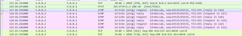
7) 验证
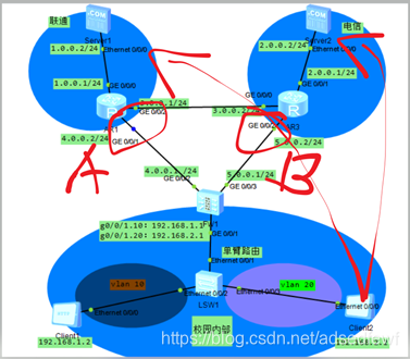
使用Clinet 2访问Server 1、Server 2的web,并对AB两处进行抓包
1) 访问Server 1时
a) A点抓包没有发现Clinet 2的数据包
b) B点抓包发现Clinet 2的数据包,并且IP已经替换为5.0.0.1
2) 访问Server 2时
a) A点抓包没有发现Clinet 2的数据包
b) B点抓包发现Clinet 2的数据包,并且已经替换为5.0.0.1

