一、移植环境准备
前面主要是基于QEMU虚拟机环境进行LwIP协议栈开发调试的,如果手头没有开发板可以先在个人电脑上运行QEMU虚拟机以便学习LwIP协议栈的实现原理或者开发调试过程。在实际产品中,就需要在真实的开发板上移植LwIP协议栈,并在此基础上进行开发调试了。
1.1 IoT-OS准备
现在物联网设备越来越需要操作系统支持,所以本文在有操作系统的基础上移植LwIP协议栈,选择的操作系统环境是RT-Thread,选择的开发板是STM32L475 Pandora。
在.\rt-thread-4.0.1\bsp\stm32\stm32l475-atk-pandora目录下启动env环境执行scons --dist命令,获得工程文件目录dist,将其复制出来,得到我们移植LwIP协议栈的基础环境。
复制出来的工程,修改工程总目录名为stm32l475-pandora-lwip,在该目录下打开env环境(在博客QEMU开发环境与RT-Thread系统启动中介绍过),执行“scons --target=mdk5”命令生成MDK5工程,使用Keil MDK打开project.uvprojx工程文件,编译无报错,将其烧录到STM32L475 Pandora开发板中,开发板上的红色LED灯周期性闪烁,启动串口助手putty,打开开发板的串口,执行list_device命令可以看到目前开发板上启动的设备,结果如下:

说明工程stm32l475-pandora-lwip已经基于STM32L475 Pandora移植好了,可以再次基础上开发新的功能。如果想了解RT-Thread系统启动过程和移植过程,可以参考博客:《RT-Thread启动过程》与《RT-Thread移植过程》,本文的重点是移植LwIP协议栈,这部分就略去了。
stm32l475-pandora-lwip的工程目录如下:
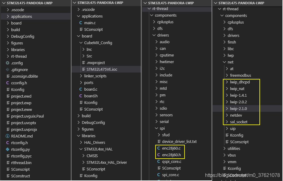
stm32l475-pandora-lwip工程源码下载地址:https://github.com/StreamAI/LwIP_Projects/tree/master/stm32l475-pandora-lwip
1.2 Network Card准备
LwIP协议栈偏上层,要想让协议栈正常工作还需要网卡提供硬件支持。网卡可以分为有线和无线两种,常见的有线网卡一般是以太网卡比如ENC28J60,常见的无线网卡一般是WI-FI网卡比如AP6181。Wi-Fi网卡还涉及到Wi-Fi协议栈的移植,这里选择有线网卡ENC28J60为LwIP协议栈的运行提供硬件支持,Wi-Fi协议栈待后续再专门介绍。
首先看看ENC28J60的典型电路:
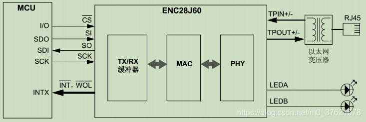
ENC28J60网卡包括PHY与MAC模块,具有TX/RX缓冲器,使用SPI接口与MCU通信,支持中断引脚触发。我手头的ENC28J60网卡是从正点原子官方旗舰店采购的,通过NRF Wireless接口插到STM32L475 Pandora开发板上。
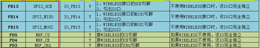
查询STM32L475 Pandora开发板I / O引脚分配表可知,NRF Wireless相关的接口如下:
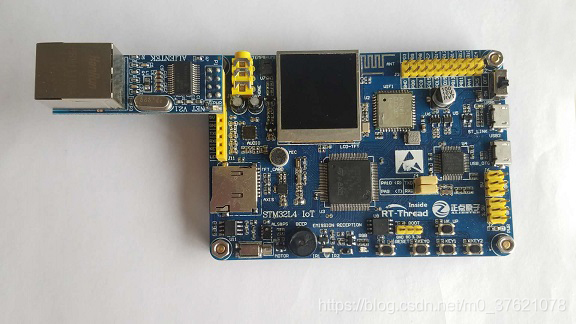
把ENC28J60模块插到STM32L475 Pandora开发板上,图示如下:
STM32L475 SPI接口通讯我在之前的博客:《STM32L4 SPI + QSPI + HAL》与《RT-Thread SPI设备对象管理》中已经详细介绍过了,本文就不再赘述了。
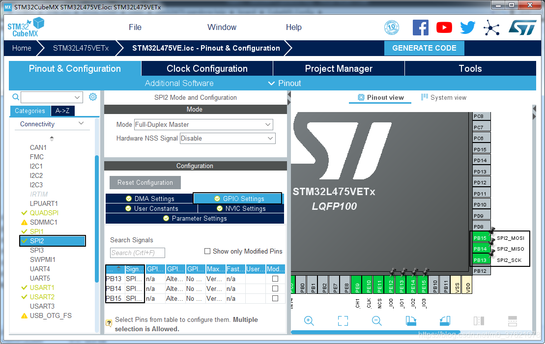
我们先把底层的SPI2接口配置好,打开board\CubeMX_Config\STM32L475VE.ioc文件,可以看到SPI2已经配置好了,不需要我们再重新配置,SPI2配置界面如下(注意引脚号与上表要一致,这里只需要配置SPI通信的三个引脚,片选CS由软件配置):
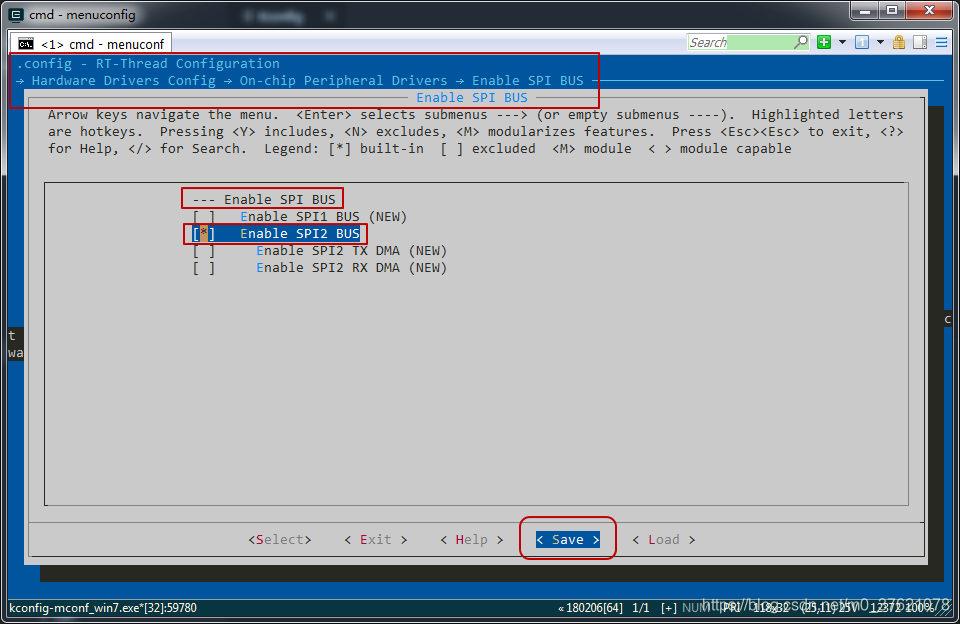
在env环境中执行menuconfig命令打开图形化配置界面,使能SPI2外设并保存配置,配置界面如下:
二、LwIP协议栈移植
2.1 工程中加入网卡与协议栈代码
从上面的工程目录可以看出,RT-Thread驱动框架中包含enc28j60的驱动,我们只需要启用相应的条件依赖宏就可以了,从编译控制脚本文件rt-thread\components\drivers\spi\SConscript可知,enc28j60驱动的条件依赖宏为RT_USING_ENC28J60,我们据此在菜单配置脚本文件board\Kconfig文件中新增ENC28J60网卡的配置选项如下:
// board\Kconfig
......
menu "Board extended module Drivers"
    config BSP_USING_ENC28J60
        bool "Enable ENC28J60"
        select BSP_USING_SPI2
        select RT_USING_ENC28J60
        default n
......
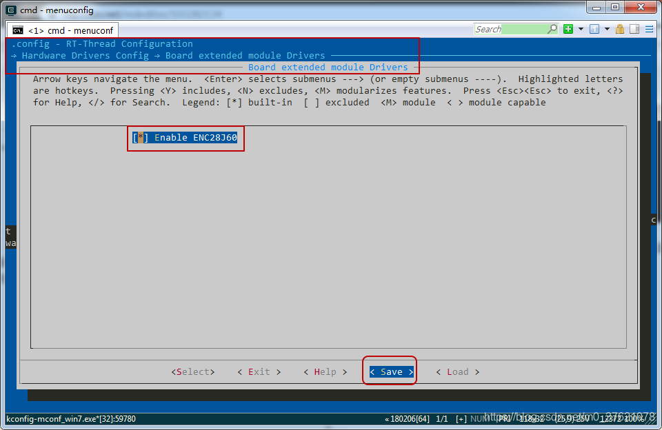
保存配置项,在env环境中执行menuconfig命令,打开图形化配置界面,使能刚才配置的ENC28J60网卡驱动,配置界面如下:
在保存配置时弹出了警告窗口:
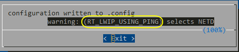
这个主要是因为启用LwIP协议栈条件依赖宏,LwIP协议栈配置中有一项跟ping命令相关的宏RT_LWIP_USING_PING依赖netdev模块,而netdev模块并没有启动导致的,netdev模块是RT-Thread提供的一套网卡接口管理层,作用主要是向上提供统一的网卡接口,方便协议栈的移植。
我们进入LwIP模块配置界面,默认选择的LwIP协议栈版本是2.0.2,我们选择最新的2.1.0版本作为移植对象,配置界面如下:

为了在移植LwIP后验证移植是否成功,我们需要使用ping命令,同时为了方便后续更好物理网卡方便,我们使用RT-Thread提供的网卡接口管理层netdev模块,该模块还提供了ifconfig命令用于查看网卡信息,使能netdev模块的配置界面如下:
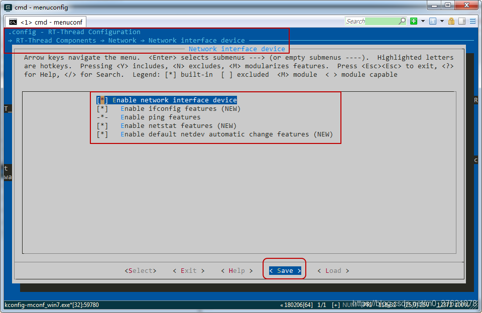
保存配置,刚才的警告消失了。到这里SPI2接口、ENC28J60网卡驱动、LwIP V2.1.0协议栈代码都已经使能了,接下来需要把各模块衔接起来,让其协调配合,完成网络数据的处理。
2.2 网卡SPI设备注册
前面的配置只是把ENC28J60网卡驱动与LwIP协议栈的代码加入的stm32l475-pandora-lwip工程中了,要想让其正常工作,还需要添加相应的移植代码。
由博客SPI设备对象管理可知,要想使用SPI设备,需要调用rt_hw_spi_device_attach函数完成SPI设备的绑定,该函数原型及实现代码如下:
// libraries\HAL_Drivers\drv_spi.c

/**
  * Attach the spi device to SPI bus, this function must be used after initialization.
  */
rt_err_t rt_hw_spi_device_attach(const char *bus_name, const char *device_name, GPIO_TypeDef *cs_gpiox, uint16_t cs_gpio_pin)
{
    RT_ASSERT(bus_name != RT_NULL);
    RT_ASSERT(device_name != RT_NULL);

    rt_err_t result;
    struct rt_spi_device *spi_device;
    struct stm32_hw_spi_cs *cs_pin;

    /* initialize the cs pin && select the slave*/
    GPIO_InitTypeDef GPIO_Initure;
    GPIO_Initure.Pin = cs_gpio_pin;
    GPIO_Initure.Mode = GPIO_MODE_OUTPUT_PP;
    GPIO_Initure.Pull = GPIO_PULLUP;
    GPIO_Initure.Speed = GPIO_SPEED_FREQ_HIGH;
    HAL_GPIO_Init(cs_gpiox, &GPIO_Initure);
    HAL_GPIO_WritePin(cs_gpiox, cs_gpio_pin, GPIO_PIN_SET);

    /* attach the device to spi bus*/
    spi_device = (struct rt_spi_device *)rt_malloc(sizeof(struct rt_spi_device));
    RT_ASSERT(spi_device != RT_NULL);
    cs_pin = (struct stm32_hw_spi_cs *)rt_malloc(sizeof(struct stm32_hw_spi_cs));
    RT_ASSERT(cs_pin != RT_NULL);
    cs_pin->GPIOx = cs_gpiox;
    cs_pin->GPIO_Pin = cs_gpio_pin;
    result = rt_spi_bus_attach_device(spi_device, device_name, bus_name, (void *)cs_pin);

    if (result != RT_EOK)
    {
        LOG_E("%s attach to %s faild, %d\n", device_name, bus_name, result);
    }

    RT_ASSERT(result == RT_EOK);

    LOG_D("%s attach to %s done", device_name, bus_name);

    return result;
}
我们在使用SPI2设备前,也需要先调用该函数,我们现在applications目录下新建ENC28J60移植代码文件enc28j60_port.c,并在该文件中新增绑定SPI2设备的代码如下:
// applications\enc28j60_port.c

#include "board.h"
#include "drv_spi.h"

// WIRELESS
#define PIN_NRF_IRQ   GET_PIN(D, 3)        // PD3 :  NRF_IRQ      --> WIRELESS
#define PIN_NRF_CE    GET_PIN(D, 4)        // PD4 :  NRF_CE       --> WIRELESS
#define PIN_NRF_CS    GET_PIN(D, 5)        // PD5 :  NRF_CS       --> WIRELESS

int enc28j60_init(void)
{
    __HAL_RCC_GPIOD_CLK_ENABLE();
    rt_hw_spi_device_attach("spi2", "spi21", GPIOD, GPIO_PIN_5);

    ......

    return 0;
}
INIT_COMPONENT_EXPORT(enc28j60_init);
到这里SPI2设备就绑定到STM32L475的SPI总线上了,STM32L475可以通过SPI总线接口函数正常访问该SPI设备了。最后使用INIT_COMPONENT_EXPORT命令可以让RT-Thread启动过程中自动调用enc28j60_init函数,以完成ENC28J60网卡的初始化,这里只完成了SPI2设备的初始化,下面继续添加ENC28J60驱动模块的初始化。
2.3 以太网设备对象管理
在博客网络接口管理中谈到LwIP网络接口管理层需要用户实现网络接口初始化、输入、输出等函数,相关函数原型如下:
// rt-thread\components\net\lwip-2.1.0\src\include\lwip\netif.h

/** Function prototype for netif init functions. Set up flags and output/linkoutput
 * callback functions in this function.
 *
 * @param netif The netif to initialize
 */
typedef err_t (*netif_init_fn)(struct netif *netif);
/** Function prototype for netif->input functions. This function is saved as 'input'
 * callback function in the netif struct. Call it when a packet has been received.
 *
 * @param p The received packet, copied into a pbuf
 * @param inp The netif which received the packet
 * @return ERR_OK if the packet was handled
 *         != ERR_OK is the packet was NOT handled, in this case, the caller has
 *                   to free the pbuf
 */
typedef err_t (*netif_input_fn)(struct pbuf *p, struct netif *inp);

#if LWIP_IPV4
/** Function prototype for netif->output functions. Called by lwIP when a packet
 * shall be sent. For ethernet netif, set this to 'etharp_output' and set
 * 'linkoutput'.
 *
 * @param netif The netif which shall send a packet
 * @param p The packet to send (p->payload points to IP header)
 * @param ipaddr The IP address to which the packet shall be sent
 */
typedef err_t (*netif_output_fn)(struct netif *netif, struct pbuf *p,
       const ip4_addr_t *ipaddr);
#endif /* LWIP_IPV4*/

#if LWIP_IPV6
/** Function prototype for netif->output_ip6 functions. Called by lwIP when a packet
 * shall be sent. For ethernet netif, set this to 'ethip6_output' and set
 * 'linkoutput'.
 *
 * @param netif The netif which shall send a packet
 * @param p The packet to send (p->payload points to IP header)
 * @param ipaddr The IPv6 address to which the packet shall be sent
 */
typedef err_t (*netif_output_ip6_fn)(struct netif *netif, struct pbuf *p,
       const ip6_addr_t *ipaddr);
#endif /* LWIP_IPV6 */

/** Function prototype for netif->linkoutput functions. Only used for ethernet
 * netifs. This function is called by ARP when a packet shall be sent.
 *
 * @param netif The netif which shall send a packet
 * @param p The packet to send (raw ethernet packet)
 */
typedef err_t (*netif_linkoutput_fn)(struct netif *netif, struct pbuf *p);
/** Function prototype for netif status- or link-callback functions. */
typedef void (*netif_status_callback_fn)(struct netif *netif);
从LwIP协议栈对网卡接口的需求可知,ENC28J60网卡至少也需要提供初始化、输入、输出与配置接口,RT-Thread为以太网设备提供了一个驱动管理框架如下:
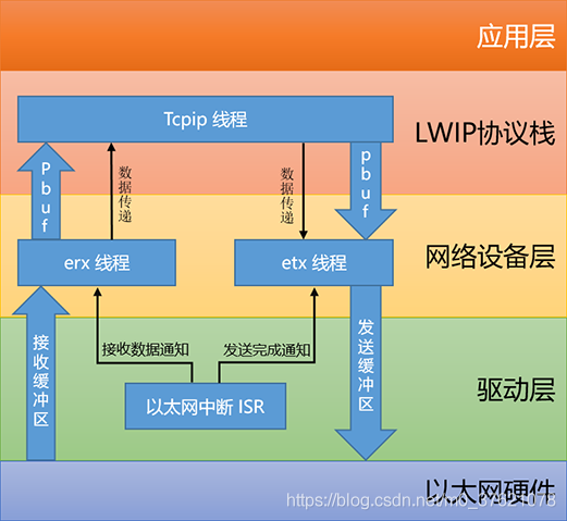
RT-Thread在网卡驱动层(比如下文介绍的ENC28J60驱动层)与LwIP协议栈间提供了一个网络设备层,该层对于以太网数据的收发采用了独立的双线程结构,erx 线程和 etx 线程在正常情况下,两者的优先级设置成相同,用户可以根据自身实际要求进行微调以侧重接收或发送。
网络设备层为以太网设备提供了一个数据管理结构eth_device,该数据结构描述与接口函数原型如下:
// rt-thread\components\net\lwip-2.1.0\src\include\netif\ethernetif.h

struct eth_device
{
    /* inherit from rt_device */
    struct rt_device parent;

    /* network interface for lwip */
    struct netif *netif;
    struct rt_semaphore tx_ack;

    rt_uint16_t flags;
    rt_uint8_t  link_changed;
    rt_uint8_t  link_status;

    /* eth device interface */
    struct pbuf* (*eth_rx)(rt_device_t dev);
    rt_err_t (*eth_tx)(rt_device_t dev, struct pbuf* p);
};

rt_err_t eth_device_ready(struct eth_device* dev);
rt_err_t eth_device_init(struct eth_device * dev, const char *name);
rt_err_t eth_device_init_with_flag(struct eth_device *dev, const char *name, rt_uint16_t flag);
rt_err_t eth_device_linkchange(struct eth_device* dev, rt_bool_t up);

int eth_system_device_init(void);
结构体eth_device继承自基设备rt_device,同时包含前面介绍的网卡接口结构体指针netif及LwIP协议栈需要的网卡状态与标志字段,最后是以太网卡的发射与接收函数指针eth_rx / eth_tx。
以太网设备的初始化过程如下:
// rt-thread\components\net\lwip-2.1.0\src\netif\ethernetif.c

rt_err_t eth_device_init(struct eth_device * dev, const char *name)
{
    rt_uint16_t flags = NETIF_FLAG_BROADCAST | NETIF_FLAG_ETHARP;

#if LWIP_IGMP
    /* IGMP support */
    flags |= NETIF_FLAG_IGMP;
#endif

    return eth_device_init_with_flag(dev, name, flags);
}

/* Keep old drivers compatible in RT-Thread */
rt_err_t eth_device_init_with_flag(struct eth_device *dev, const char *name, rt_uint16_t flags)
{
    struct netif* netif;

    netif = (struct netif*) rt_malloc (sizeof(struct netif));
    if (netif == RT_NULL)
    {
        rt_kprintf("malloc netif failed\n");
        return -RT_ERROR;
    }
    rt_memset(netif, 0, sizeof(struct netif));

    /* set netif */
    dev->netif = netif;
    /* device flags, which will be set to netif flags when initializing */
    dev->flags = flags;
    /* link changed status of device */
    dev->link_changed = 0x00;
    dev->parent.type = RT_Device_Class_NetIf;
    /* register to RT-Thread device manager */
    rt_device_register(&(dev->parent), name, RT_DEVICE_FLAG_RDWR);
    rt_sem_init(&(dev->tx_ack), name, 0, RT_IPC_FLAG_FIFO);

    /* set name */
    netif->name[0] = name[0];
    netif->name[1] = name[1];

    /* set hw address to 6 */
    netif->hwaddr_len   = 6;
    /* maximum transfer unit */
    netif->mtu          = ETHERNET_MTU;

    /* set linkoutput */
    netif->linkoutput   = ethernetif_linkoutput;

    /* get hardware MAC address */
    rt_device_control(&(dev->parent), NIOCTL_GADDR, netif->hwaddr);

#if LWIP_NETIF_HOSTNAME
    /* Initialize interface hostname */
    netif->hostname = "rtthread";
#endif /* LWIP_NETIF_HOSTNAME */

    /* if tcp thread has been started up, we add this netif to the system */
    if (rt_thread_find("tcpip") != RT_NULL)
    {
        ip4_addr_t ipaddr, netmask, gw;

#if !LWIP_DHCP
        ipaddr.addr = inet_addr(RT_LWIP_IPADDR);
        gw.addr = inet_addr(RT_LWIP_GWADDR);
        netmask.addr = inet_addr(RT_LWIP_MSKADDR);
#else
        IP4_ADDR(&ipaddr, 0, 0, 0, 0);
        IP4_ADDR(&gw, 0, 0, 0, 0);
        IP4_ADDR(&netmask, 0, 0, 0, 0);
#endif
        netifapi_netif_add(netif, &ipaddr, &netmask, &gw, dev, eth_netif_device_init, tcpip_input);
    }

#ifdef RT_USING_NETDEV
    /* network interface device flags synchronize */
    netdev_flags_sync(netif);
#endif /* RT_USING_NETDEV */

    return RT_EOK;
}
在以太网设备初始化过程中,主要完成了以太网设备注册rt_device_register,网卡输出接口ethernetif_linkoutput注册,网卡接口添加netifapi_netif_add等工作。
网卡接口添加函数netifapi_netif_add向LwIP协议栈注册了网卡初始化接口eth_netif_device_init与网卡输入接口tcpip_input,并将以太网设备句柄注册到lwip网卡接口对象的state字段,实现eth_device与netif设备对象的相互访问。我们依次看这几个接口函数的实现代码(限于篇幅,只节选部分):
// rt-thread\components\net\lwip-2.1.0\src\netif\ethernetif.c
static err_t eth_netif_device_init(struct netif *netif)
{
struct eth_device *ethif;
ethif = (struct eth_device*)netif->state;
if (ethif != RT_NULL)
{
rt_device_t device;
#ifdef RT_USING_NETDEV
/* network interface device register */
netdev_add(netif);
#endif /* RT_USING_NETDEV */
/* get device object */
device = (rt_device_t) ethif;
if (rt_device_init(device) != RT_EOK)
{
return ERR_IF;
}
/* copy device flags to netif flags */
netif->flags = (ethif->flags & 0xff);
netif->mtu = ETHERNET_MTU;
/* set output */
netif->output = etharp_output;
#if LWIP_IPV6
......
#endif /* LWIP_IPV6 */
/* set default netif */
if (netif_default == RT_NULL)
netif_set_default(ethif->netif);
#if LWIP_DHCP
/* set interface up */
netif_set_up(ethif->netif);
/* if this interface uses DHCP, start the DHCP client */
dhcp_start(ethif->netif);
#else
/* set interface up */
netif_set_up(ethif->netif);
#endif
if (ethif->flags & ETHIF_LINK_PHYUP)
{
/* set link_up for this netif */
netif_set_link_up(ethif->netif);
}
return ERR_OK;
}
return ERR_IF;
}
static err_t ethernetif_linkoutput(struct netif *netif, struct pbuf *p)
{
#ifndef LWIP_NO_TX_THREAD
struct eth_tx_msg msg;
struct eth_device* enetif;
RT_ASSERT(netif != RT_NULL);
enetif = (struct eth_device*)netif->state;
/* send a message to eth tx thread */
msg.netif = netif;
msg.buf = p;
if (rt_mb_send(ð_tx_thread_mb, (rt_uint32_t) &msg) == RT_EOK)
{
/* waiting for ack */
rt_sem_take(&(enetif->tx_ack), RT_WAITING_FOREVER);
}
#else
struct eth_device* enetif;
RT_ASSERT(netif != RT_NULL);
enetif = (struct eth_device*)netif->state;
if (enetif->eth_tx(&(enetif->parent), p) != RT_EOK)
{
return ERR_IF;
}
#endif
return ERR_OK;
}
// rt-thread\components\net\lwip-2.1.0\src\api\tcpip.c
/**
* @ingroup lwip_os
* Pass a received packet to tcpip_thread for input processing with
* ethernet_input or ip_input. Don't call directly, pass to netif_add()
* and call netif->input().
*
* @param p the received packet, p->payload pointing to the Ethernet header or
* to an IP header (if inp doesn't have NETIF_FLAG_ETHARP or
* NETIF_FLAG_ETHERNET flags)
* @param inp the network interface on which the packet was received
*/
err_t tcpip_input(struct pbuf *p, struct netif *inp)
{
#if LWIP_ETHERNET
if (inp->flags & (NETIF_FLAG_ETHARP | NETIF_FLAG_ETHERNET)) {
return tcpip_inpkt(p, inp, ethernet_input);
} else
#endif /* LWIP_ETHERNET */
return tcpip_inpkt(p, inp, ip_input);
}
以太网初始化函数eth_netif_device_init最终通过调用rt_device_init完成网卡设备初始化,同时注册了网卡输出接口etharp_output,用于向上层传递数据包。
以太网链路输出接口ethernetif_linkoutput最终是通过调用eth_device->eth_tx接口实现功能的,RT-Thread为了加快网卡的传输速率,支持为以太网卡分别创建一个数据发送线程与一个数据接收线程,专门处理以太网卡的数据收发,但数据包需要通过邮箱在进程间传递。
协议栈输入接口tcpip_input主要是把以太网卡接收到的数据包传递给lwip协议栈上层进行处理,该函数被以太网卡接收线程调用,当以太网卡接收到数据包后会调用该接口函数将数据包传递给lwip协议栈上层处理。
以太网发送接收线程,及通过邮箱发送接收数据的过程代码如下:
// rt-thread\components\net\lwip-2.1.0\src\netif\ethernetif.c
#ifndef LWIP_NO_TX_THREAD
/* Ethernet Tx Thread */
static void eth_tx_thread_entry(void* parameter)
{
struct eth_tx_msg* msg;
while (1)
{
if (rt_mb_recv(ð_tx_thread_mb, (rt_ubase_t *)&msg, RT_WAITING_FOREVER) == RT_EOK)
{
struct eth_device* enetif;
RT_ASSERT(msg->netif != RT_NULL);
RT_ASSERT(msg->buf != RT_NULL);
enetif = (struct eth_device*)msg->netif->state;
if (enetif != RT_NULL)
{
/* call driver's interface */
if (enetif->eth_tx(&(enetif->parent), msg->buf) != RT_EOK)
{
/* transmit eth packet failed */
}
}
/* send ACK */
rt_sem_release(&(enetif->tx_ack));
}
}
}
#endif
#ifndef LWIP_NO_RX_THREAD
/* Ethernet Rx Thread */
static void eth_rx_thread_entry(void* parameter)
{
struct eth_device* device;
while (1)
{
if (rt_mb_recv(ð_rx_thread_mb, (rt_ubase_t *)&device, RT_WAITING_FOREVER) == RT_EOK)
{
struct pbuf *p;
/* check link status */
if (device->link_changed)
{
int status;
rt_uint32_t level;
level = rt_hw_interrupt_disable();
status = device->link_status;
device->link_changed = 0x00;
rt_hw_interrupt_enable(level);
if (status)
netifapi_netif_set_link_up(device->netif);
else
netifapi_netif_set_link_down(device->netif);
}
/* receive all of buffer */
while (1)
{
if(device->eth_rx == RT_NULL) break;
p = device->eth_rx(&(device->parent));
if (p != RT_NULL)
{
/* notify to upper layer */
if( device->netif->input(p, device->netif) != ERR_OK )
{
LWIP_DEBUGF(NETIF_DEBUG, ("ethernetif_input: Input error\n"));
pbuf_free(p);
p = NULL;
}
}
else break;
}
}
else
{
LWIP_ASSERT("Should not happen!\n",0);
}
}
}
#endif
#ifndef LWIP_NO_RX_THREAD
rt_err_t eth_device_ready(struct eth_device* dev)
{
if (dev->netif)
/* post message to Ethernet thread */
return rt_mb_send(ð_rx_thread_mb, (rt_uint32_t)dev);
else
return ERR_OK; /* netif is not initialized yet, just return. */
}
......
#endif
// rt-thread\components\drivers\spi\enc28j60.c
void enc28j60_isr(void)
{
eth_device_ready(&enc28j60_dev.parent);
NET_DEBUG("enc28j60_isr\r\n");
}
// libraries\HAL_Drivers\drv_eth.c
void HAL_ETH_RxCpltCallback(ETH_HandleTypeDef *heth)
{
rt_err_t result;
result = eth_device_ready(&(stm32_eth_device.parent));
if (result != RT_EOK)
LOG_E("RX err = %d", result);
}
从上面的代码可以看出,eth_tx_thread_entry线程通过邮箱接收到消息后通过eth_device->eth_tx接口将数据发送出去,邮箱消息是被前面注册的ethernetif_linkoutput接口函数发送的。
eth_rx_thread_entry线程通过邮箱接收到信号后,通过调用eth_device->eth_rx接口从以太网卡接收数据,并通过调用netif->input接口(前面注册的tcpip_input接口函数)将数据传递给lwip协议栈上层处理,邮箱消息是通过以太网设备的接收中断处理函数enc28j60_isr间接发送的。
上面调用以太网接口eth_device_ready用于发送以太网接收中断/接收完成信号的函数有两个,分别是enc28j60_isr与HAL_ETH_RxCpltCallback,读者可能会疑惑这里起作用的是哪个函数?我们使用ENC28J60以太网卡,起作用的自然是enc28j60_isr,STM32互联网型号是支持以太网ETH MAC模块的,对于只有PHY物理层的网卡比如DM9000,需要借助STM32提供的ETH模块实现MAC层的功能,自然就需要借助STM32 ETH库函数接口比如HAL_ETH_RxCpltCallback来发送接收完成信号便于上层处理接收到的数据了。
2.4 ENC28J60设备注册
熟悉了eth_device设备驱动框架,接下来我们需要向eth_device设备驱动层注册以太网设备,并实现其eth_rx与eth_tx接口函数功能。
下面先看ENC28J60以太网卡的数据结构描述:
// rt-thread\components\drivers\spi\enc28j60.h

struct net_device
{
    /* inherit from ethernet device */
    struct eth_device parent;

    /* interface address info. */
    rt_uint8_t  dev_addr[MAX_ADDR_LEN]; /* hw address   */

    rt_uint8_t emac_rev;
    rt_uint8_t phy_rev;
    rt_uint8_t phy_pn;
    rt_uint32_t phy_id;

    /* spi device */
    struct rt_spi_device *spi_device;
    struct rt_mutex lock;
};
ENC28J60网卡结构体net_device继承自以太网设备eth_device,同时包含了MAC地址、SPI设备句柄rt_spi_device、PHY物理层的一些管理变量等。
前面已经完成了SPI2设备的注册,接下来看看ENC28J60设备的初始化与注册:
// rt-thread\components\drivers\spi\enc28j60.c

static struct net_device  enc28j60_dev;

rt_err_t enc28j60_attach(const char *spi_device_name)
{
    struct rt_spi_device *spi_device;

    spi_device = (struct rt_spi_device *)rt_device_find(spi_device_name);
    if (spi_device == RT_NULL)
    {
        NET_DEBUG("spi device %s not found!\r\n", spi_device_name);
        return -RT_ENOSYS;
    }

    /* config spi */
    {
        struct rt_spi_configuration cfg;
        cfg.data_width = 8;
        cfg.mode = RT_SPI_MODE_0 | RT_SPI_MSB; /* SPI Compatible Modes 0 */
        cfg.max_hz = 20 * 1000 * 1000; /* SPI Interface with Clock Speeds Up to 20 MHz */
        rt_spi_configure(spi_device, &cfg);
    } /* config spi */

    memset(&enc28j60_dev, 0, sizeof(enc28j60_dev));

    rt_event_init(&tx_event, "eth_tx", RT_IPC_FLAG_FIFO);
    enc28j60_dev.spi_device = spi_device;

    /* detect device */
    {
        uint16_t value;

        /* perform system reset. */
        spi_write_op(spi_device, ENC28J60_SOFT_RESET, 0, ENC28J60_SOFT_RESET);
        rt_thread_delay(1); /* delay 20ms */

        enc28j60_dev.emac_rev = spi_read(spi_device, EREVID);
        value = enc28j60_phy_read(spi_device, PHHID2);
        enc28j60_dev.phy_rev = value & 0x0F;
        enc28j60_dev.phy_pn = (value >> 4) & 0x3F;
        enc28j60_dev.phy_id = (enc28j60_phy_read(spi_device, PHHID1) | ((value >> 10) << 16)) << 3;

        if (enc28j60_dev.phy_id != 0x00280418)
            return RT_EIO;
    }

    /* OUI 00-04-A3 (hex): Microchip Technology, Inc. */
    enc28j60_dev.dev_addr[0] = 0x00;
    enc28j60_dev.dev_addr[1] = 0x04;
    enc28j60_dev.dev_addr[2] = 0xA3;
    /* set MAC address, only for test */
    enc28j60_dev.dev_addr[3] = 0x12;
    enc28j60_dev.dev_addr[4] = 0x34;
    enc28j60_dev.dev_addr[5] = 0x56;

    /* init rt-thread device struct */
    enc28j60_dev.parent.parent.type    = RT_Device_Class_NetIf;
#ifdef RT_USING_DEVICE_OPS
    enc28j60_dev.parent.parent.ops     = &enc28j60_ops;
#else
    enc28j60_dev.parent.parent.init    = enc28j60_init;
    enc28j60_dev.parent.parent.open    = enc28j60_open;
    enc28j60_dev.parent.parent.close   = enc28j60_close;
    enc28j60_dev.parent.parent.read    = enc28j60_read;
    enc28j60_dev.parent.parent.write   = enc28j60_write;
    enc28j60_dev.parent.parent.control = enc28j60_control;
#endif

    /* init rt-thread ethernet device struct */
    enc28j60_dev.parent.eth_rx  = enc28j60_rx;
    enc28j60_dev.parent.eth_tx  = enc28j60_tx;

    rt_mutex_init(&enc28j60_dev.lock, "enc28j60", RT_IPC_FLAG_FIFO);

    eth_device_init(&(enc28j60_dev.parent), "e0");

    return RT_EOK;
}
ENC28J60设备注册函数enc28j60_attach完成SPI设备的配置,net_device设备的配置,最后通过调用前面介绍的接口函数eth_device_init完成eth_device设备的初始化与注册。
根据这个过程,我们只需要调用函数enc28j60_attach即可完成ENC28J60设备的初始化与注册,在enc28j60_port.c文件中添加ENC28J60初始化与注册代码如下:
// applications\enc28j60_port.c

#include "board.h"
#include "drv_spi.h"
#include "enc28j60.h"
......

int enc28j60_init(void)
{
    __HAL_RCC_GPIOD_CLK_ENABLE();
    rt_hw_spi_device_attach("spi2", "spi21", GPIOD, GPIO_PIN_5);

    /* attach enc28j60 to spi. spi21 cs - PD6 */
    enc28j60_attach("spi21");
	......
    return 0;
}
INIT_COMPONENT_EXPORT(enc28j60_init);
到这里ENC28J60网卡已经能够初始化并注册到RT-Thread设备管理框架中,但移植工作还没有结束。
前面提到了ENC28J60接收中断处理函数void enc28j60_isr(void),该函数怎么触发呢?ENC28J60使用的NRF WIRELESS接口是有中断引脚NRF_IRQ的,我们只需要把该函数注册为NRF_IRQ引脚的外部信号触发中断执行函数即可。不熟悉GPIO引脚中断配置的可以参考博客:PIN设备对象管理,在enc28j60_port.c文件中添加配置NRF_IRQ引脚并绑定中断服务函数enc28j60_isr的代码如下(增加条件宏定义,以免后续条件宏关闭后编译运行错误):
// applications\enc28j60_port.c

#include "board.h"

#ifdef BSP_USING_ENC28J60

#include "board.h"
#include "drv_spi.h"
#include "enc28j60.h"
#include "drivers/pin.h"

// WIRELESS
#define PIN_NRF_IRQ   GET_PIN(D, 3)        // PD3 :  NRF_IRQ      --> WIRELESS
#define PIN_NRF_CE    GET_PIN(D, 4)        // PD4 :  NRF_CE       --> WIRELESS
#define PIN_NRF_CS    GET_PIN(D, 5)        // PD5 :  NRF_CS       --> WIRELESS

int enc28j60_init(void)
{
    __HAL_RCC_GPIOD_CLK_ENABLE();
    rt_hw_spi_device_attach("spi2", "spi21", GPIOD, GPIO_PIN_5);

    /* attach enc28j60 to spi. spi21 cs - PD6 */
    enc28j60_attach("spi21");

    /* init interrupt pin */
    rt_pin_mode(PIN_NRF_IRQ, PIN_MODE_INPUT_PULLUP);
    rt_pin_attach_irq(PIN_NRF_IRQ, PIN_IRQ_MODE_FALLING, (void(*)(void*))enc28j60_isr, RT_NULL);
    rt_pin_irq_enable(PIN_NRF_IRQ, PIN_IRQ_ENABLE);

    return 0;
}
INIT_COMPONENT_EXPORT(enc28j60_init);

#endif /* BSP_USING_ENC28J60 */
到这里ENC28J60网卡就配置好了,在env环境中执行“scons --target=mdk5”命令生成Keil MDK工程,打开MDK工程文件project.uvprojx,编译报错如下:

提示不能打开该文件,我们查找unistd.h文件所在路径为rt-thread\components\libc\compilers\armlibc\sys\unistd.h,看看包含该文件需要依赖哪些条件宏,查看该目录下的编译控制脚本文件rt-armlibc\SConscript,代码如下:
// rt-thread\components\libc\compilers\armlibc\sys\unistd.h
......
#ifdef RT_USING_DFS

#define STDIN_FILENO    0       /* standard input file descriptor */
#define STDOUT_FILENO   1       /* standard output file descriptor */
#define STDERR_FILENO   2       /* standard error file descriptor */

#include <dfs_posix.h>
#else
#define _FREAD      0x0001  /* read enabled */
......
#define _FNOCTTY    0x8000  /* don't assign a ctty on this open */

#define O_RDONLY    0       /* +1 == FREAD */
......
#define O_SYNC      _FSYNC
#endif


// rt-thread\components\libc\compilers\armlibc\SConscript
......
if rtconfig.PLATFORM == 'armcc' or rtconfig.PLATFORM == 'armclang':
    group = DefineGroup('libc', src, depend = ['RT_USING_LIBC'],
        CPPPATH = CPPPATH, CPPDEFINES = CPPDEFINES)
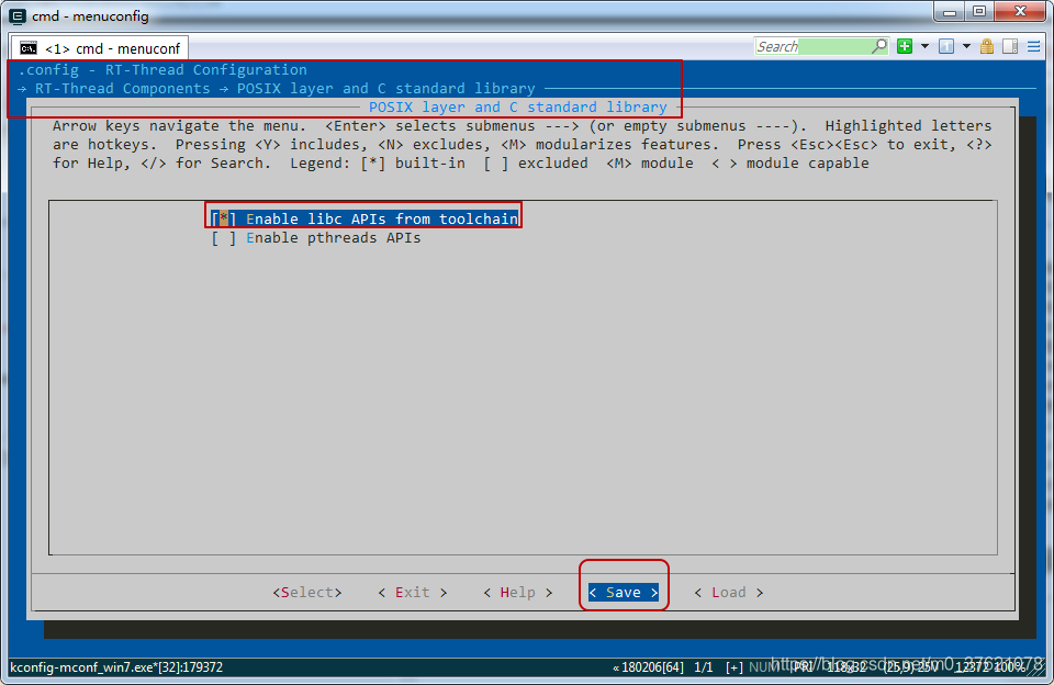
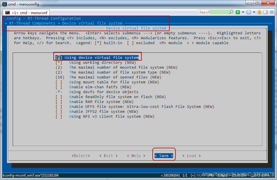
从上面的代码可以看出,包含unistd.h文件所在目录需要打开条件宏RT_USING_LIBC,我们在menuconfig中打开RT_USING_LIBC,配置界面如下:
重新在env中执行“scons --target=mdk5”命令,打开MDK工程文件project.uvprojx,编译报错如下:
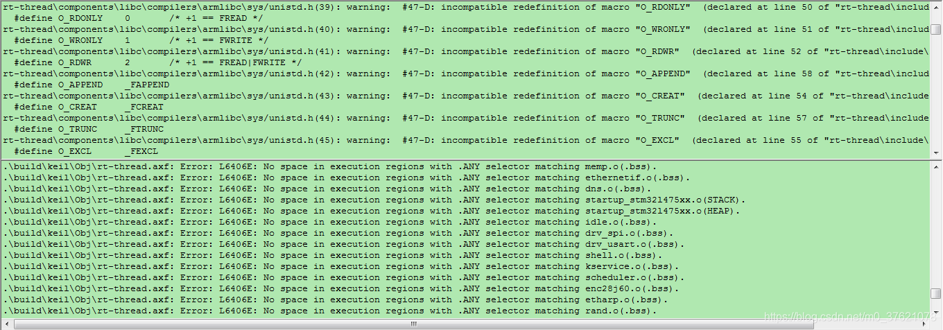
上面的警告提示是宏定义冲突,而且正好跟前面unistd.h文件中的宏定义一样,再回头看看unistd.h文件中的宏定义,在条件宏RT_USING_DFS开启后,就不再重新定义这些宏定义了,宏定义冲突也就解决了,我们先在menuconfig中开启条件宏定义RT_USING_DFS,配置界面如下:
下面的错误提示是内存空间不够用了,打开Keil MDK配置ROM与RAM的链接脚本文件,发现,只使用了STM32L475 SRAM2 32KB的空间,我们改为使用SRAM1 96KB的空间,并把SRAM2的配置注释掉(汇编语言注释符号’;’),修改后的配置如下图所示:
// board\linker_scripts\link.sct
......
LR_IROM1 0x08000000 0x00080000  {    ; load region size_region
  ER_IROM1 0x08000000 0x00080000  {  ; load address = execution address
   *.o (RESET, +First)
   *(InRoot$$Sections)
   .ANY (+RO)
  }
  RW_IRAM1 0x20000000 0x00018000  {  ; RW data
   .ANY (+RW +ZI)
;  RW_IRAM2 0x10000000 0x00008000  {  ; RW data
;   .ANY (+RW +ZI)
  }
}
再打开RT-Thread配置ROM与RAM的文件board\board.h,发现堆空间起始地址HEAP_BEGIN与SRAM1开始地址一致,这是有问题的,在堆之前还需要保存RW段数据与ZI段数据,如下图所示:
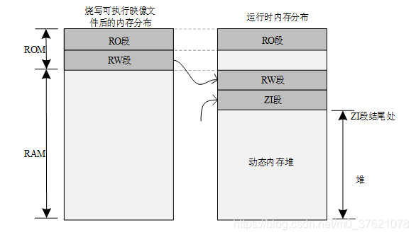
因此我们需要重定义HEAP_BEGIN在ZI段结尾,该怎么获得ZI段结束地址呢?我们找到RT-Thread为STM32提供的移植模板文件bsp\stm32\libraries\templates\stm32l4xx\board\board.h,从里面复制出相应的内容到我们工程的board.h文件,修改代码如下:
// board\board.h
......
#define STM32_FLASH_START_ADRESS       ((uint32_t)0x08000000)
#define STM32_FLASH_SIZE               (512 * 1024)
#define STM32_FLASH_END_ADDRESS        ((uint32_t)(STM32_FLASH_START_ADRESS + STM32_FLASH_SIZE))

#define STM32_SRAM1_SIZE               (96)
#define STM32_SRAM1_START              (0x20000000)
#define STM32_SRAM1_END                (STM32_SRAM1_START + STM32_SRAM1_SIZE * 1024)

#if defined(__CC_ARM) || defined(__CLANG_ARM)
extern int Image$$RW_IRAM1$$ZI$$Limit;
#define HEAP_BEGIN      ((void *)&Image$$RW_IRAM1$$ZI$$Limit)
#elif __ICCARM__
#pragma section="CSTACK"
#define HEAP_BEGIN      (__segment_end("CSTACK"))
#else
extern int __bss_end;
#define HEAP_BEGIN      ((void *)&__bss_end)
#endif

#define HEAP_END                       STM32_SRAM1_END
......
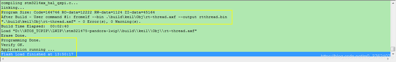
重新配置完MDK与RT-Thread的ROM与RAM地址及空间,在env中执行“scons --target=mdk5”命令,打开MDK工程文件project.uvprojx,编译无报错,将程序烧录到我们的STM32L475 Pandora开发板中,烧录完成界面如下:
使用putty串口工具与Pandora开发板交互,查询设备列表,执行ifconfig命令与ping www.baidu.com命令,结果如下:
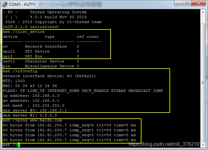
ENC28J60网卡已正常注册名称为e0的网络接口设备,ifconfig命令查看该网卡接口的IP与DNS地址已配置,ping命令可以正常收到远程主机的回送报文,说明网络连通正常,到这里基于ENC28J60移植LWIP协议栈的工作完成了。
如果想了解LwIP协议栈在操作系统网络分层架构中的位置,及其各层的调用关系,可以参考博客:网络分层结构 + netdev/SAL原理。
三、LwIP示例程序验证
这里选择前面使用QEMU验证用的UDP与TCP示例程序,使用Sequential API编写。
3.1 UDP回送示例
把前面QEMU验证用的UDP回送程序复制过来,也即在applications目录下新建seqapi_udp_demo.c文件,并打开该文件编辑实现代码如下:
// applications\seqapi_udp_demo.c

#include "lwip/api.h"
#include "rtthread.h"

static void udpecho_thread(void *arg)
{
  static struct netconn *conn;
  static struct netbuf *buf;
  static ip_addr_t *addr;
  static unsigned short port;

  err_t err;
  LWIP_UNUSED_ARG(arg);

  conn = netconn_new(NETCONN_UDP);
  LWIP_ASSERT("con != NULL", conn != NULL);
  netconn_bind(conn, NULL, 7);

  while (1) {
    err = netconn_recv(conn, &buf);
    if (err == ERR_OK) {
      addr = netbuf_fromaddr(buf);
      port = netbuf_fromport(buf);
      rt_kprintf("addr: %ld, poty: %d.\n", addr->addr, port);

	    err = netconn_send(conn, buf);
      if(err != ERR_OK) {
          LWIP_DEBUGF(LWIP_DBG_ON, ("netconn_send failed: %d\n", (int)err));
      }
      netbuf_delete(buf);
      rt_thread_mdelay(100);
    }
  }
}

static void udpecho_init(void)
{
  sys_thread_new("udpecho", udpecho_thread, NULL, 1024, 25);
  rt_kprintf("Startup a udp echo server.\n");
}
MSH_CMD_EXPORT_ALIAS(udpecho_init, seqapi_udpecho, sequential api udpecho init);
在env环境执行“scons --target=mdk5”命令,打开MDK工程文件project.uvprojx,编译无报错,将程序烧录到我们的STM32L475 Pandora开发板中,示例运行结果如下:
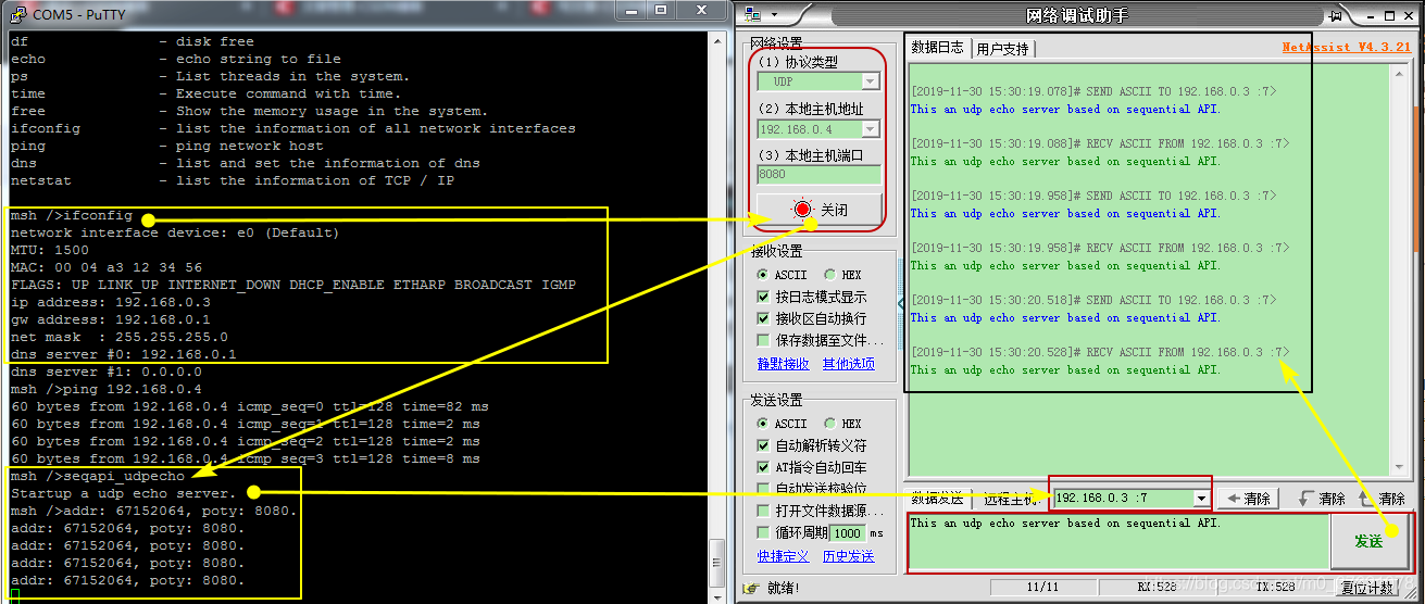
UDP回送程序运行正常,说明我们移植LWIP可以正常工作,接下来再看一个TCP示例程序。
本示例工程源码下载地址:https://github.com/StreamAI/LwIP_Projects/tree/master/stm32l475-pandora-lwip
3.2 HTTP控制设备示例
既然我们已经将lwip协议栈移植到开发板上了,开发板上不缺传感器与执行器,这里就在之前TCP HTTP服务程序仅展示一个网页的基础上,加入网页控制LED灯亮灭的功能。
在applications目录下新建seqapi_tcp_demo.c文件,打开该文件并编辑实现代码如下:
// applications\seqapi_tcp_demo.c

#include "lwip/api.h"
#include "rtthread.h"
#include "board.h"
#include <stdbool.h>

/* defined the LED1 pin: PE9 */
#define LED1_PIN    GET_PIN(E, 9)

const static char http_html_hdr[] = "HTTP/1.1 200 OK\r\nContent-type: text/html\r\n\r\n";
const static char http_index_html[] = "<html><head><title>Congrats!</title></head><body><h1>Welcome to LwIP 2.1.0 HTTP server!</h1> \
                                                        <center><p>This is a test page based on netconn API.</center></body></html>";
const unsigned char LedOn_Data[] ="\
	<HTML>	\
	<head><title>LED Monitor</title></head> \
	<center>	\
	<p>   \
	<center>LED is on!!</center>\
	<form method=post action=\"off\" name=\"ledform\"> \
	<font size=\"2\">Change LED status:</font>  \
	<input type=\"submit\" value=\"off\">	\
	</form> \
	</p>  \
	</center>  \
	</HTML>";

const unsigned char LedOff_Data[] ="\
	<HTML>	\
	<head><title>LED Monitor</title></head> \
	<center>	\
	<p>   \
	<center>LED is off!!</center>\
	<form method=post action=\"on\" name=\"ledform\"> \
	<font size=\"2\">Change LED status:</font>  \
	<input type=\"submit\" value=\"on\">	\
	</form> \
	</p>  \
	</center>  \
	</HTML>";

static bool led_on = false;

/*send page*/
static void httpserver_send_html(struct netconn *conn, bool led_status)
{
    netconn_write(conn, http_html_hdr, sizeof(http_html_hdr)-1, NETCONN_NOCOPY);
    /* Send our HTML page */
    netconn_write(conn, http_index_html, sizeof(http_index_html)-1, NETCONN_NOCOPY);

    /* Send our HTML page */
	 if(led_status == true)
        netconn_write(conn, LedOn_Data, sizeof(LedOn_Data)-1, NETCONN_NOCOPY);
	 else
	  	netconn_write(conn, LedOff_Data, sizeof(LedOff_Data)-1, NETCONN_NOCOPY);

}
/** Serve one HTTP connection accepted in the http thread */

static void httpserver_serve(struct netconn *conn)
{
  struct netbuf *inbuf;
  char *buf;
  u16_t buflen;
  err_t err;

  /* Read the data from the port, blocking if nothing yet there.
   We assume the request (the part we care about) is in one netbuf */
  err = netconn_recv(conn, &inbuf);

  if (err == ERR_OK) {
    netbuf_data(inbuf, (void**)&buf, &buflen);
    /* Is this an HTTP GET command? (only check the first 5 chars, since
    there are other formats for GET, and we're keeping it very simple )*/
    if (buflen>=5 && buf[0]=='G' && buf[1]=='E' && buf[2]=='T' &&
        buf[3]==' ' && buf[4]=='/' ) {

      /* Send the HTML header
             * subtract 1 from the size, since we dont send the \0 in the string
             * NETCONN_NOCOPY: our data is const static, so no need to copy it
       */
    httpserver_send_html(conn, led_on);
    }
	else if(buflen>=8 && buf[0]=='P' && buf[1]=='O' && buf[2]=='S' && buf[3]=='T')
	{
		if(buf[6]=='o' && buf[7]=='n'){		//请求打开LED
		    led_on = true;
            rt_pin_write(LED1_PIN, PIN_LOW);
		}else if(buf[6]=='o' && buf[7]=='f' && buf[8]=='f'){	//请求关闭LED
		    led_on = false;
            rt_pin_write(LED1_PIN, PIN_HIGH);
	    }

		httpserver_send_html(conn, led_on);
	}

	netbuf_delete(inbuf);
  }
  /* Close the connection (server closes in HTTP) */
  netconn_close(conn);

  /* Delete the buffer (netconn_recv gives us ownership,
   so we have to make sure to deallocate the buffer) */
}

/** The main function, never returns! */
static void httpserver_thread(void *arg)
{
  struct netconn *conn, *newconn;
  err_t err;
  LWIP_UNUSED_ARG(arg);

  /* Create a new TCP connection handle */
  conn = netconn_new(NETCONN_TCP);
  LWIP_ERROR("http_server: invalid conn", (conn != NULL), return;);

  led_on = true;
  rt_pin_write(LED1_PIN, PIN_LOW);

  /* Bind to port 80 (HTTP) with default IP address */
  netconn_bind(conn, NULL, 80);

  /* Put the connection into LISTEN state */
  netconn_listen(conn);

  do {
    err = netconn_accept(conn, &newconn);
    if (err == ERR_OK) {
      httpserver_serve(newconn);
      netconn_delete(newconn);
    }
  } while(err == ERR_OK);
  LWIP_DEBUGF(HTTPD_DEBUG, ("http_server_netconn_thread: netconn_accept received error %d, shutting down", err));
  netconn_close(conn);
  netconn_delete(conn);
}

/** Initialize the HTTP server (start its thread) */
void httpserver_init()
{
  /* set LED0 pin mode to output */
  rt_pin_mode(LED1_PIN, PIN_MODE_OUTPUT);

  sys_thread_new("http_server_netconn", httpserver_thread, NULL, 1024, TCPIP_THREAD_PRIO + 1);
  rt_kprintf("Startup a tcp web server.\n");
}
MSH_CMD_EXPORT_ALIAS(httpserver_init, seqapi_httpserver, sequential api httpserver init);
在env环境执行“scons --target=mdk5”命令,打开MDK工程文件project.uvprojx,编译无报错,将程序烧录到我们的STM32L475 Pandora开发板中,示例运行结果如下:
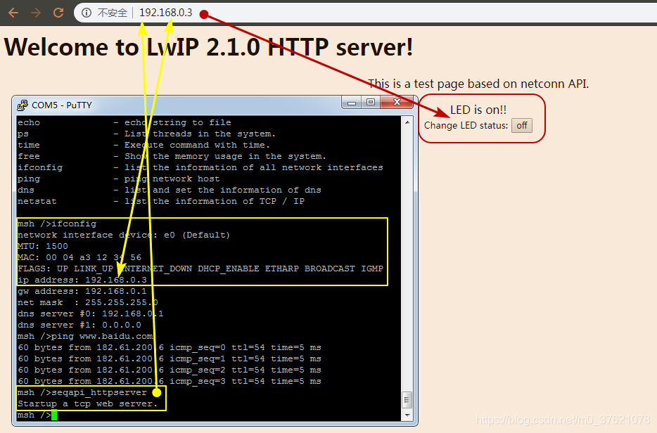
seqapi_httpserver运行起来后,Pandora开发板上的蓝灯亮起了,在浏览器中输入开发板的IP地址,可以正常访问控制LED灯的网页界面。点击网页上的off按钮后,开发板上的LED蓝灯灭了,同时网页状态更新为"LED is off",界面如下:
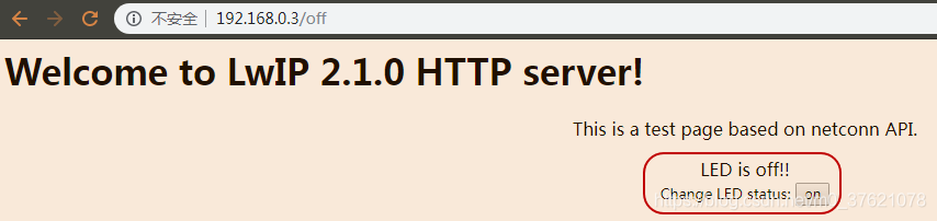
网页可以正常控制开发板上的LED灯亮灭,也就实现了通过TCP/IP网络远程控制物联网设备的功能,在ENC28J60网卡上移植LwIP协议栈运行正常。
本示例工程源码下载地址:https://github.com/StreamAI/LwIP_Projects/tree/master/stm32l475-pandora-lwip
