链路聚合概述
链路聚合(Link Aggregation)是将多个物理接口当作一个逻辑接口,以增加带宽和提供线路冗余,链路聚合的带宽理论上相当于所包含的物理接口带宽总和,非常适用于企业核心网络中,同时参与捆绑的某个成员接口或链路损坏,不影响聚合链路的正常工作,提供了冗余性。华为设备支持的链路聚合协议是LACP(Link Aggregation Control Protocol)。在华为设备中由多个物理接口捆绑成逻辑接口,该接口被称为Eth-Trunk接口。链路聚合相关的标准由IEEE802.3ad定义。
成员接口
将成员接口加入Eth-Trunk时,需要注意以下问题:
每个Eth-Tnuk接口下最多可以包含8个成员接口。
成员接口不能单独配置任何功能和静态MAC地址。
成员接口加入Eth-Trunk时,必须为默认的hybrid类型接口。
Eth-Trunk接口不能嵌套,即成员接口不能是Eth-Trunk。
一个以太网接口只能加入一个Eth-Trunk接口,如果需要加入其他Eth-Trunk接口,必须先退出原来的Eth-Trunk接口。
一个Eth-Trunk接口中的成员接口必须是同一类型,即FE口和GE口不能加入同一个Eth-Trunk接口。
可以将不同接口板上的以太网接口加入同一个Eth-Trunk。
如果本地设备使用了Eth-Trunk,与成员接口直连的对端接口也必须捆绑为Eth-Trunk接口,这样两端才能正常通信。
当成员接口的速率不一致时,实际使用中速率小的接口可能会出现拥塞,导致丢包。
当成员接口加入Eth-Trunk后,学习MAC地址时是按照Eth-Trunk来学习的,而不是按照成员接口来学习的。
链路聚合模式
华为设备支持的链路聚合模式有手工负载分担模式和静态LACP模式。
手工负载分担模式。手工负载分担模式没有LACP协议报文的参与,所有的配置均由手工完成。如加入多个成员接口,该模式下所有的接口均处于转发状态,实现链路的负载分担。它支持的负载分担方式包括目的MAC、源MAC、源MAC异或目的MAC、源IP、目的IP、源IP异或目的IP。手工负载分担模式通常应用在对端设备不支持LACP协议的情况下。
静态LACP模式。静态LACP模式是线路两端利用LACP协议进行协商,从而确定活动接口和非活动接口的链路聚合方式,在该模式下,创建Eth-Trunk、加入Eth-Trunk成员接口需由手工完成,而确定活动接口和非活动接口则由LACP协议协商产生,静态LACP模式也称为M:N模式。这种方式同时可以实现链路负载分担和冗余备份的双重功能。在链路聚合组中M条链路处于活动状态,转发数据并负载分担,而另外N条链路处于非活动状态,不转发数据。当M条链路中有链路出现故障时,系统会自动从N条备份链路中选择优先级最高的接替故障链路,并开始转发数据。
静态LACP模式与手工负载分担模式的主要区别为:
静态LACP模式可以有备份链路。
而手工负载分担模式中所有成员接口均处于转发状态,分担负载流量,除非线路故障。
在静态LACP模式下,聚合组两端的设备中,需要选择一端为主动端,而另外一端为被动端,通常情况下:
LACP优先级较高的一端为主动端
LACP优先級较低的一端为被动端
如果优先级一样MAC地址小的一端为主动端。
区分主动端与被动端的目的是保证两端设备最终确定的活动接口一致,否则两端都按照本端各自的接口优先級来选择活动接口,最终两端所确定的活动接口很可能不一致,聚合链路也就无法建立。
如下图所示,Switch A选择上面两个接口为活动接口,而Switch B选择下面两个接口为活动接口,因为Switch A的优先级比较高。所以最终的活动接口两端都以Switch A为准。因此应首先确定主动端,被动端按照主动端侧的接口优先级来选择活动接口。
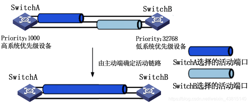
这里注意一下:交换机里priority数字越低,优先级越大;路由器相反
负载均衡模式(可选)
详细的讲解咱也不很清楚,哈哈。如果链路过多的话,建议选择使用下这个dst-mac,官方说能提高带宽咱就用用呗!那位大佬要是懂得话,可以留言联系我,咱们互相学习!
链路聚合的主要作用是提高带宽以及增加冗余,而普遍的做法就是在多条物理链路上实行负载分担、常用的负载分担模式包括:
dst-ip(目的IP地址)模式:从目的IP地址、出端口的TCP/UDP端口号中分别选择指定位的3bit数值进行异或运算,根据运算结选择Eth-Trunk表中对应的出接口。
dst-mac(目的MAC地址)模式:从目的MAC地址、VLAN ID、以太网类型及入端口信息中分别选择指定位的3bit数值进行异或运算,根据运算结果选择Eth-Trunk表中对应的出接口。
src-ip(源IP地址)模式:从源IP地址、入端口的TCP/UDP端口号中分别选择指定位的3bit数值进行异或运算,根据运算结果选择Eth-Trunk收表中对应的出接口。
src-mac(源MAC地址)模式:从源MAC地址、VLAN ID、以太网类型及入端口信息中分别选择指定位的3bit数值进行异或运算,根据运算结果选择Eth-Trunk表中对应的出接口。
src-dst-ip(源IP地址与目的IP地址的异或)模式:对目的IP地址,源IP地址两种负载分担模式的运算结果进行异或运算,根据运算结果选择Eth-Trunk表中对应的出接口。
src-dst-mac(源MAC地址与目的MAC地址的异或)模式:从目的MAC地址、源MAC地址、VLAN ID、以太网类型及入端口信息中分别选择指定位的3bit数值进行异或运算,根据运算结果选择Eth-Trunk表中对应的出接口。
案例环境
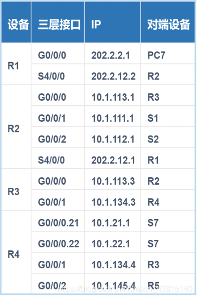
某公司网络拓扑结构如下图所示,其网络架构为接入层以及核心层。接入层二层交换机( S3-S7 )下面接若干个客户端( 图中以1台为例 ),核心交换网络由两台三层交换机( S1、S2 )构成。并通过以太通道提高带宽以及增加冗余。三层方面主要分为两个部分,其中一部分是由OSPF协议构建的网络区域。另一部分是由RIPv2协议构建的网络区域。内网R4下面通过二层交换机连接两个VLAN网络,并通过单臂路由提供VLAN之间的转发,R5连接一台服务器,可供内网、外网同时访问,内网通过R2连接外部网络,外部网络由R1和一台PC7组成。
需求描述
1)链路聚合
S1和S2使用链路聚合将两条物理线路聚合成一条逻辑线路,用于实现链路负载分担和备份,设置S1为LACP主动端,要求辑链路基于目的MAC的方式进行负载分担。
2)VLAN及VLAN间路由
要求实现所有VLAN客户端和服务器之间的互通。
3)OSPF和RIP部分
R2、R3、S1和S2开启OSPF进程110。所有的设备都属于OSPF区域0。R3、R4和R5开启RIPv2协议,R3的G 0/0/1接口和R4的G 0/0/1接口、R4的G 0/0/2接口和R5的G 0/0/2接口都能够收发RIPv2协议报文。
4)路由重分发
要求0SPF环境中所有计算机能够和RIP环境中所有计算机、服务器相互访问。
5)NAT及访问控制
内网环境中所有计算机及服务器除了10.1.21-22.0/24这两个网段外,都可以访问互联网,并通过R2转换为固定IP(202.2.12.100),服务器的公网映射地址为202.2.12.200,要求PC7可以通过该地址访问内网服务器。
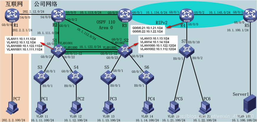
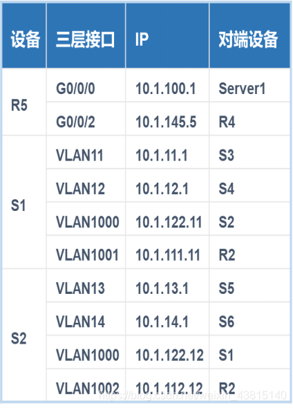
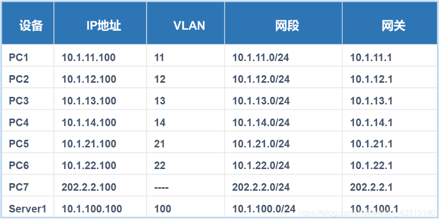
公司的计算机网络及VLAN信息如表所示。
ensp拓扑

实施流程
1.配置客户端IP地址
2.配置链路聚合
S1的配置如下:
The device is running!
system-view
Enter system view, return user view with Ctrl+Z.
[Huawei]sysname S1
[S1]
Feb 28 2019 09:32:14-08:00 S1 DS/4/DATASYNC_CFGCHANGE:OID 1.3.6.1.4.1.2011.5.25.
191.3.1 configurations have been changed. The current change number is 4, the ch
ange loop count is 0, and the maximum number of records is 4095.
[S1]undo info enable //禁止弹出信息中心,不然弹出的信息报文影响操作
Info: Information center is disabled.
[S1]lacp priority 1000 //配置S1设备的系统LACP优先级
[S1]interface Eth-Trunk 12 //创建链路聚合逻辑接口,名称为Eth-Trunk 12
[S1-Eth-Trunk12]mode lacp-static //配置静态LACP模式
[S1-Eth-Trunk12]load-balance dst-mac //配置负载均衡模式为目标MAC地址
[S1-Eth-Trunk12]trunkport GigabitEthernet 0/0/11 //添加成员接口 g 0/0/11
Info: This operation may take a few seconds. Please wait for a moment…done.
[S1-Eth-Trunk12]trunkport GigabitEthernet 0/0/12 //添加成员接口 g 0/0/12
Info: This operation may take a few seconds. Please wait for a moment…done.
[S1-Eth-Trunk12]quit
**S2的配置如下:
The device is running!
system-view
Enter system view, return user view with Ctrl+Z.
[Huawei]sysname S2
[S2]undo info enable
Info: Information center is disabled.
[S2]interface Eth-Trunk 12
[S2-Eth-Trunk12]mode lacp-static
[S2-Eth-Trunk12]trunkport GigabitEthernet 0/0/11
Info: This operation may take a few seconds. Please wait for a moment…done.
[S2-Eth-Trunk12]
[S2-Eth-Trunk12]trunkport GigabitEthernet 0/0/12
Info: This operation may take a few seconds. Please wait for a moment…done.
[S2-Eth-Trunk12]quit
3.配置VLAN间路由
S1的配置如下:
[S1]vlan batch 11 to 14 1000 to 1002 //批量创建VLAN11-14、VLAN1000-1002
Info: This operation may take a few seconds. Please wait for a moment…done.
[S1]interface Eth-Trunk 12 //进入聚合链路接口
[S1-Eth-Trunk12]port link-type trunk //配置链路聚合接口模式为Trunk
[S1-Eth-Trunk12]port trunk allow-pass vlan 11 to 14 1000 to 1002 //Trunk允许VLAN11-14、VLAN1000-1002
[S1-Eth-Trunk12]interface g 0/0/21
[S1-GigabitEthernet0/0/21]port link-type trunk //链路聚合接口模式为Trunk
[S1-GigabitEthernet0/0/21]port trunk allow-pass vlan all //允许所有VLAN
[S1-GigabitEthernet0/0/21]interface g 0/0/22
[S1-GigabitEthernet0/0/22]port link-type trunk
[S1-GigabitEthernet0/0/22]port trunk allow-pass vlan all
[S1-GigabitEthernet0/0/22]interface vlanif 11 //进入VLAN11的虚接口
[S1-Vlanif11]ip address 10.1.11.1 24
[S1-Vlanif11]interface vlanif 12
[S1-Vlanif12]ip address 10.1.12.1 24
[S1-Vlanif12]quit
S2的配置如下:
[S2]vlan batch 11 to 14 1000 to 1002
Info: This operation may take a few seconds. Please wait for a moment…done.
[S2]interface Eth-Trunk 12
[S2-Eth-Trunk12]port link-type trunk
[S2-Eth-Trunk12]port trunk allow-pass vlan all
[S2-Eth-Trunk12]interface g 0/0/23
[S2-GigabitEthernet0/0/23]port link-type trunk
[S2-GigabitEthernet0/0/23]port trunk allow-pass vlan all
[S2-GigabitEthernet0/0/23]interface g 0/0/24
[S2-GigabitEthernet0/0/24]port link-type trunk
[S2-GigabitEthernet0/0/24]port trunk allow-pass vlan all
[S2-GigabitEthernet0/0/24]quit
[S2]interface vlanif13
[S2-Vlanif13]ip address 10.1.13.1 24
[S2-Vlanif13]interface vlanif14
[S2-Vlanif14]ip address 10.1.14.1 24
[S2-Vlanif14]quit
S3的配置如下:
The device is running!
system-view
Enter system view, return user view with Ctrl+Z.
[Huawei]undo info enable
Info: Information center is disabled.
[Huawei]sysname S3
[S3]vlan batch 11 to 14
Info: This operation may take a few seconds. Please wait for a moment…done.
[S3]interface GigabitEthernet 0/0/1
[S3-GigabitEthernet0/0/1]port link-type trunk
[S3-GigabitEthernet0/0/1]port trunk allow-pass vlan all
[S3-GigabitEthernet0/0/1]interface e 0/0/1
[S3-Ethernet0/0/1]port link-type access
[S3-Ethernet0/0/1]port default vlan 11
[S3-Ethernet0/0/1]quit
S4的配置如下:
The device is running!
system-view
Enter system view, return user view with Ctrl+Z.
[Huawei]undo info enable
Info: Information center is disabled.
[Huawei]sysname S4
[S4]vlan batch 11 to 14
Info: This operation may take a few seconds. Please wait for a moment…done.
[S4]interface GigabitEthernet 0/0/1
[S4-GigabitEthernet0/0/1]port link-type trunk
[S4-GigabitEthernet0/0/1]port trunk allow-pass vlan all
[S4-GigabitEthernet0/0/1]interface e 0/0/1
[S4-Ethernet0/0/1]port link-type access
[S4-Ethernet0/0/1]port default vlan 12
[S4-Ethernet0/0/1]quit
S5的配置如下:
The device is running!
system-view
Enter system view, return user view with Ctrl+Z.
[Huawei]undo info enable
Info: Information center is disabled.
[Huawei]sysname S5
[S5]vlan batch 11 to 14
Info: This operation may take a few seconds. Please wait for a moment…done.
[S5]interface GigabitEthernet 0/0/1
[S5-GigabitEthernet0/0/1]port link-type trunk
[S5-GigabitEthernet0/0/1]port trunk allow-pass vlan all
[S5-GigabitEthernet0/0/1]interface e 0/0/1
[S5-Ethernet0/0/1]port link-type access
[S5-Ethernet0/0/1]port default vlan 13
[S5-Ethernet0/0/1]quit
S6的配置如下:
The device is running!
system-view
Enter system view, return user view with Ctrl+Z.
[Huawei]undo info enable
Info: Information center is disabled.
[Huawei]sysname S6
[S6]vlan batch 11 to 14
Info: This operation may take a few seconds. Please wait for a moment…done.
[S6]interface g 0/0/1
[S6-GigabitEthernet0/0/1]port link-type trunk
[S6-GigabitEthernet0/0/1]port trunk allow-pass vlan all
[S6-GigabitEthernet0/0/1]interface e 0/0/1
[S6-Ethernet0/0/1]port link-type access
[S6-Ethernet0/0/1]port default vlan 14
[S6-Ethernet0/0/1]quit
4.配置单臂路由
华为的单臂路由配置和 Cisco几乎没有差别,主要有两项配置,一项是交换机和路由器Trunk配置,另外一项是路由器的子接口配置及关联相应的VLAN。
R4的配置如下:
The device is running!
system-view
Enter system view, return user view with Ctrl+Z.
[Huawei]undo info enable
Info: Information center is disabled.
[Huawei]sysname R4
[R4]interface GigabitEthernet 0/0/0.21
[R4-GigabitEthernet0/0/0.21]ip address 10.1.21.1 24
[R4-GigabitEthernet0/0/0.21]dot1q termination vid 21
[R4-GigabitEthernet0/0/0.21]arp broadcast enable
[R4-GigabitEthernet0/0/0.21]interface g 0/0/0.22
[R4-GigabitEthernet0/0/0.22]ip address 10.1.22.1 24
[R4-GigabitEthernet0/0/0.22]dot1q termination vid 22
[R4-GigabitEthernet0/0/0.22]arp broadcast enable
[R4-GigabitEthernet0/0/0.22]quit
S7的配置如下:
The device is running!
system-view
Enter system view, return user view with Ctrl+Z.
[Huawei]undo info enable
Info: Information center is disabled.
[Huawei]sysname S7
[S7]vlan batch 21 22
Info: This operation may take a few seconds. Please wait for a moment…done.
[S7]interface e 0/0/10
[S7-Ethernet0/0/10]port link-type trunk
[S7-Ethernet0/0/10]port trunk allow-pass vlan all
[S7-Ethernet0/0/10]interface e 0/0/1
[S7-Ethernet0/0/1]port link-type access
[S7-Ethernet0/0/1]port default vlan 21
[S7-Ethernet0/0/1]interface e 0/0/2
[S7-Ethernet0/0/2]port link-type access
[S7-Ethernet0/0/2]port default vlan 22
[S7-Ethernet0/0/2]quit
5.配置RIP和OSPF
华为的RIP配置和Cisco命令几乎一致,注意把no变成undo即可。配置OSPF时和Cisco不同,它不是一条 network命令同时宣告网络和区域,而是在某个区域下面的子模式宣告相关的网络。
S1的配置如下:
system-view
Enter system view, return user view with Ctrl+Z.
[S1]interface g 0/0/1
[S1-GigabitEthernet0/0/1]port link-type access
[S1-GigabitEthernet0/0/1]port default vlan 1001
[S1-GigabitEthernet0/0/1]quit
[S1]interface vlanif 1000
[S1-Vlanif1000]ip address 10.1.122.11 24
[S1-Vlanif1000]interface vlanif 1001
[S1-Vlanif1001]ip address 10.1.111.11 24
[S1-Vlanif1001]quit
[S1]ospf 110
[S1-ospf-110]area 0
[S1-ospf-110-area-0.0.0.0]network 10.1.111.0 0.0.0.255
[S1-ospf-110-area-0.0.0.0]network 10.1.122.0 0.0.0.255
[S1-ospf-110-area-0.0.0.0]network 10.1.11.0 0.0.0.255
[S1-ospf-110-area-0.0.0.0]network 10.1.12.0 0.0.0.255
[S1-ospf-110-area-0.0.0.0]quit
S2的配置如下:
system-view
Enter system view, return user view with Ctrl+Z.
[S2]interface g 0/0/2
[S2-GigabitEthernet0/0/2]port link-type access
[S2-GigabitEthernet0/0/2]port default vlan 1002
[S2-GigabitEthernet0/0/2]interface vlanif 1000
[S2-Vlanif1000]ip address 10.1.122.12 24
[S2-Vlanif1000]interface vlanif 1002
[S2-Vlanif1002]ip address 10.1.112.12 24
[S2-Vlanif1002]quit
[S2]ospf 110
[S2-ospf-110]area 0
[S2-ospf-110-area-0.0.0.0]network 10.1.112.0 0.0.0.255
[S2-ospf-110-area-0.0.0.0]network 10.1.122.0 0.0.0.255
[S2-ospf-110-area-0.0.0.0]network 10.1.13.0 0.0.0.255
[S2-ospf-110-area-0.0.0.0]network 10.1.14.0 0.0.0.255
[S2-ospf-110-area-0.0.0.0]quit
[S2-ospf-110]quit
R2的配置如下:
system-view
Enter system view, return user view with Ctrl+Z.
[Huawei]undo info enable
Info: Information center is disabled.
[Huawei]sysname R2
[R2]interface g 0/0/0
[R2-GigabitEthernet0/0/0]ip address 10.1.113.1 24
[R2-GigabitEthernet0/0/0]undo shutdown
Info: Interface GigabitEthernet0/0/0 is not shutdown.
[R2-GigabitEthernet0/0/0]interface g 0/0/1
[R2-GigabitEthernet0/0/1]ip address 10.1.111.1 24
[R2-GigabitEthernet0/0/1]undo shutdown
Info: Interface GigabitEthernet0/0/1 is not shutdown.
[R2-GigabitEthernet0/0/1]interface g 0/0/2
[R2-GigabitEthernet0/0/2]ip address 10.1.112.1 24
[R2-GigabitEthernet0/0/2]undo shutdown
Info: Interface GigabitEthernet0/0/2 is not shutdown.
[R2-GigabitEthernet0/0/2]ospf 110
[R2-ospf-110]area 0
[R2-ospf-110-area-0.0.0.0]network 10.1.113.0 0.0.0.255
[R2-ospf-110-area-0.0.0.0]network 10.1.111.0 0.0.0.255
[R2-ospf-110-area-0.0.0.0]network 10.1.112.0 0.0.0.255
[R2-ospf-110-area-0.0.0.0]quit
[R2-ospf-110]quit
R3的配置如下:
system-view
Enter system view, return user view with Ctrl+Z.
[Huawei]undo info enable
Info: Information center is disabled.
[Huawei]sysname R3
[R3]interface g 0/0/0
[R3-GigabitEthernet0/0/0]ip address 10.1.113.3 24
[R3-GigabitEthernet0/0/0]undo shutdown
Info: Interface GigabitEthernet0/0/0 is not shutdown.
[R3-GigabitEthernet0/0/0]interface g 0/0/1
[R3-GigabitEthernet0/0/1]ip address 10.1.134.3 24
[R3-GigabitEthernet0/0/1]undo shutdown
Info: Interface GigabitEthernet0/0/1 is not shutdown.
[R3-GigabitEthernet0/0/1]ospf 110
[R3-ospf-110]area 0
[R3-ospf-110-area-0.0.0.0]network 10.1.113.0 0.0.0.255
[R3-ospf-110-area-0.0.0.0]quit
[R3-ospf-110]quit
[R3]rip
[R3-rip-1]version 2
[R3-rip-1]undo summary
[R3-rip-1]network 10.0.0.0
[R3-rip-1]quit
R4的配置如下:
sys
Enter system view, return user view with Ctrl+Z.
[R4]interface g0/0/1
[R4-GigabitEthernet0/0/1]ip address 10.1.134.4 24
[R4-GigabitEthernet0/0/1]undo shutdown
Info: Interface GigabitEthernet0/0/1 is not shutdown.
[R4-GigabitEthernet0/0/1]int g0/0/2
[R4-GigabitEthernet0/0/2]ip address 10.1.145.4 24
[R4-GigabitEthernet0/0/2]undo shutdown
Info: Interface GigabitEthernet0/0/2 is not shutdown.
[R4-GigabitEthernet0/0/1]quit
[R4]rip
[R4-rip-1]version 2
[R4-rip-1]undo summary
[R4-rip-1]network 10.0.0.0
[R4-rip-1]quit
R5的配置如下:
sys
Enter system view, return user view with Ctrl+Z.
[Huawei]undo info enable
Info: Information center is disabled.
[Huawei]sysname R5
[R5]interface g 0/0/2
[R5-GigabitEthernet0/0/2]ip address 10.1.145.5 24
[R5-GigabitEthernet0/0/2]undo shutdown
Info: Interface GigabitEthernet0/0/2 is not shutdown.
[R5-GigabitEthernet0/0/2]interface g 0/0/0
[R5-GigabitEthernet0/0/0]ip address 10.1.100.1 24
[R5-GigabitEthernet0/0/0]undo shutdow
Info: Interface GigabitEthernet0/0/0 is not shutdown.
[R5-GigabitEthernet0/0/0]rip
[R5-rip-1]version 2
[R5-rip-1]undo summary
[R5-rip-1]network 10.0.0.0
[R5-rip-1]quit
6.配置路由重分发
华为的路由重分发是通过 import-route命令实现的,不管导入什么协议。都要加上进程ID号。和 Cisco一样,如果把A协议导入B协议中,那么首先要进入B的路由进程中,执行导入A的命令。反之同理。
R3的配置如下:
sys
Enter system view, return user view with Ctrl+Z.
[R3]ospf 110
[R3-ospf-110]import-route rip 1
[R3-ospf-110]rip
[R3-rip-1]import-route ospf 110
[R3-rip-1]quit
7.配置NAT及访问控制(这里不再过多解释,后面博客会更新详解NAT)
华为的NAT转换直接配置在外部接口模式下。需要转换的内部流量通过ACL抓取,而转换后的内部全局地址通过配置NAT组实现。
R2的配置如下:
[R2]interface Serial 4/0/0
[R2-Serial4/0/0]ip address 202.2.12.1 24
[R2-Serial4/0/0]undo shutdown
Info: Interface Serial4/0/0 is not shutdown.
[R2-Serial4/0/0]quit
[R2]ip route-static 0.0.0.0 0.0.0.0 202.2.12.2
[R2]ospf 110
[R2-ospf-110]default-route-advertise
[R2-ospf-110]quit
[R2]nat address-group 1 202.2.12.100 202.2.12.100
[R2]acl 2000
[R2-acl-basic-2000]rule 0 permit source 10.1.0.0 0.0.15.255
[R2-acl-basic-2000]rule 10 permit source 10.1.100.0 0.0.0.255
[R2-acl-basic-2000]quit
[R2]interface s 4/0/0
[R2-Serial4/0/0]nat outbound 2000 address-group 1
[R2-Serial4/0/0]nat server global 202.2.12.200 inside 10.1.100.100
[R2-Serial4/0/0]quit
[R2]acl 3000
[R2-acl-adv-3000]rule 0 deny ip source 10.1.21.0 0.0.0.255 destination 202.0.0.0 0.255.255.255
[R2-acl-adv-3000]rule 5 deny ip source 10.1.22.0 0.0.0.255 destination 202.0.0.0 0.255.255.255
[R2-acl-adv-3000]quit
[R2]interface g 0/0/0
[R2-GigabitEthernet0/0/0]traffic-filter inbound acl 3000
[R2-GigabitEthernet0/0/0]quit
R1的配置如下:
sys
Enter system view, return user view with Ctrl+Z.
[Huawei]undo info enable
Info: Information center is disabled.
[Huawei]sysname R1
[R1]interface s 4/0/0
[R1-Serial4/0/0]ip address 202.2.12.2 24
[R1-Serial4/0/0]undo shutdown
Info: Interface Serial4/0/0 is not shutdown.
[R1-Serial4/0/0]interface g 0/0/0
[R1-GigabitEthernet0/0/0]ip address 202.2.2.1 24
[R1-GigabitEthernet0/0/0]undo shutdown
Info: Interface GigabitEthernet0/0/0 is not shutdown.
[R1-GigabitEthernet0/0/0]quit
8.调整全局路由
//R3的配置如下:
[R3]rip
[R3-rip-1]default-route originate
[R3-rip-1]quit
验证nat转换
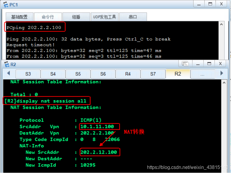
在PC1上尝试ping互联网,然后在R2上查看转换条目.可以看到源地址 10.1. 11.100 转换为202.2.12.100。如图所示。
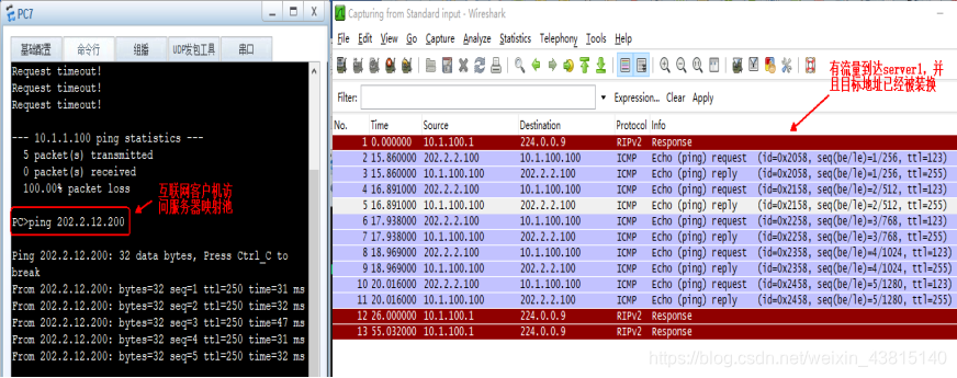
在 PC7 上尝试ping服务器映射后的地址 202.2.12.200,在 R5 和 Server1 之间抓包可以抓到该流量,说明该流量到达R2之后,被重定向到内部服务器,如图所示。
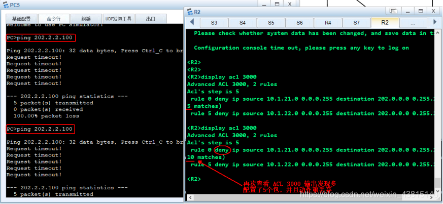
实验目标是 VLAN21 和 VLAN22 不能访问互联网。在本案例中,不管是通过在应用NAT的 ACL 2000
上排除网段,还是在 ACL 3000中拒绝流量都可以实现这个目标,结果如图所示。