A differential has on hand drive car, the use of two DC motor to achieve the moving car at a given speed, to complete the straight running, steering, acceleration, braking and other complex motion.
Motor powered using 12v DC motor, with encoder feedback, so that closed loop speed control may be employed, where the PWM drive motor, the speed control block is as follows:
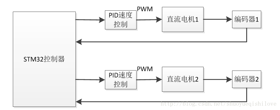
From the above block diagram, controls the rotation of two DC motor, the motor speed can be varied by changing the size of the PWM duty cycle PWM output STM32 through the timer module, since our goal is to control the motor to run at any speed range at a given speed, here we need to use closed loop control thought, obtain real-time speed of the motor by the encoder, and by calculating the difference between a given speed, the deviation as the input PID controller, PWM duty cycle to change the size of the PID control , so that the running speed of the motor at a given speed.
Motor driver chip is used herein TB6612, the chip can be very convenient to run two drive DC motor that drives following logic table:
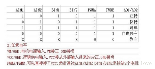
The AIN1, AIN2 of different combinations can be realized reversing and parking the motor, the PWM input pin of PWMA, by entering a different duty cycle may change the speed of motor speed. BIN1, BIN2, PWMB is another way to control the motor of the pin.
First, we need to use the STM32 timer module output two PWM wave, which is the first step to turn the motor up. Initialization PWM:
 //初始化PWM引脚

  void motorPWMPin_init(void)

  {

  GPIO_InitTypeDef GPIO_InitStructure;

  RCC_AHB1PeriphClockCmd(RCC_AHB1Periph_GPIOE,ENABLE);

  GPIO_InitStructure.GPIO_Mode = GPIO_Mode_AF;

  GPIO_InitStructure.GPIO_OType = GPIO_OType_PP;

  GPIO_InitStructure.GPIO_PuPd = GPIO_PuPd_NOPULL;

  GPIO_InitStructure.GPIO_Speed = GPIO_Speed_100MHz;

  GPIO_InitStructure.GPIO_Pin = GPIO_Pin_9 | GPIO_Pin_11 ;//TIM1_Chn_1,TIM1_Chn_2

  GPIO_Init(GPIOE,&GPIO_InitStructure);

  GPIO_PinAFConfig (GPIOE., GPIO_PinSource9, GPIO_AF_TIM1);

  GPIO_PinAFConfig (GPIOE., GPIO_PinSource11, GPIO_AF_TIM1);

  }

  // initialize the PWM

  void motorPWM_init ( void )

  {

  TIM_TimeBaseInitTypeDef TIM_TimeBaseInitStrecture;

  TIM_OCInitTypeDef TIM_OCInitStructure;

  RCC_APB2PeriphClockCmd (RCC_APB2Periph_TIM1, the ENABLE);

  TIM_TimeBaseInitStrecture.TIM_Period = 400 ; / * frequency 20KHz iS apos the PWM * /

  TIM_TimeBaseInitStrecture.TIM_Prescaler = 21 is - . 1 ; // the clock frequency is set to 8MHz TIM1

  TIM_TimeBaseInitStrecture.TIM_ClockDivision = TIM_CKD_DIV1;

  TIM_TimeBaseInitStrecture.TIM_CounterMode = TIM_CounterMode_Up;//定时器向上计数

  TIM_TimeBaseInitStrecture.TIM_RepetitionCounter = 0;

  TIM_TimeBaseInit(TIM1,&TIM_TimeBaseInitStrecture);

  TIM_OCInitStructure.TIM_OCMode = TIM_OCMode_PWM1;

  TIM_OCInitStructure.TIM_OCPolarity = TIM_OCPolarity_High ;

  TIM_OCInitStructure.TIM_OutputState = TIM_OutputState_Enable;

  TIM_OCInitStructure.TIM_OCIdleState = TIM_OCIdleState_Reset;

  TIM_OC1Init(TIM1,&TIM_OCInitStructure);

  TIM_OC2Init(TIM1,&TIM_OCInitStructure);

  // TIM_Cmd(TIM1,ENABLE);

  TIM_CtrlPWMOutputs(TIM1,ENABLE);

  }
Then initializes the motor control pins programmed as follows:
  // Initialization of motor control pin

  void motorCtrlPin_init ( void )

  {

  GPIO_InitTypeDef GPIO_InitStructure;

  RCC_AHB1PeriphClockCmd (RCC_AHB1Periph_GPIOE, the ENABLE);

  // PE7, PE8 control the motor A, PE9, PE10 controlling the motor B

  GPIO_InitStructure.GPIO_Pin = GPIO_Pin_7 | GPIO_Pin_8 | GPIO_Pin_13 | GPIO_Pin_14 | GPIO_Pin_10;

  GPIO_InitStructure.GPIO_Mode = GPIO_Mode_OUT;

  GPIO_InitStructure.GPIO_OType = GPIO_OType_PP;

  GPIO_InitStructure.GPIO_Speed = GPIO_Speed_100MHz; // 100MHz

  GPIO_InitStructure.GPIO_PuPd = GPIO_PuPd_DOWN;

  GPIO_Init (GPIOE.,&GPIO_InitStructure);

  }
Note that the multiplexed pin talk timer TIM1 setting PWM output pin, and the motor control pins provided only as a simple push-pull mode to.
Next we need to use two timers encoder function for reading a real rotational speed of the motor, I is used herein timer 3 and 4.
Here encoder lower accuracy Hall induction type encoder, but the basic control accuracy to meet the requirements of the driver code as follows:
  void encoderA_init(void)

  {

  GPIO_InitTypeDef GPIO_InitStructure;

  NVIC_InitTypeDef NVIC_InitStructure;

  TIM_TimeBaseInitTypeDef TIM_TimeBaseStructure;

  TIM_ICInitTypeDef TIM_ICInitStructure;

  /*CLOCK Enable*/

  RCC_APB1PeriphClockCmd(RCC_APB1Periph_TIM3, ENABLE);

  RCC_AHB1PeriphClockCmd(RCC_AHB1Periph_GPIOC, ENABLE); //PC6,PC7

  GPIO_InitStructure.GPIO_Pin = GPIO_Pin_6 | GPIO_Pin_7;

  GPIO_InitStructure.GPIO_Mode = GPIO_Mode_AF;//复用引脚模式

  GPIO_InitStructure.GPIO_Speed = GPIO_Speed_100MHz; //100MHz

  GPIO_InitStructure.GPIO_OType = GPIO_OType_OD;

  GPIO_InitStructure.GPIO_PuPd = GPIO_PuPd_NOPULL; //无上下拉

  /*Configure PC6,PC7 as encoder A,B Input*/

  GPIO_PinAFConfig(GPIOC,GPIO_PinSource6,GPIO_AF_TIM3);

  GPIO_PinAFConfig(GPIOC,GPIO_PinSource7,GPIO_AF_TIM3);

  GPIO_Init(GPIOC,&GPIO_InitStructure); //initialize PORTC

  /* Timer configuration in Encoder mode */

  /* Enable the TIM3 Update Interrupt */

  NVIC_InitStructure.NVIC_IRQChannel = TIM3_IRQn;

  NVIC_InitStructure.NVIC_IRQChannelPreemptionPriority = 0x02;

  NVIC_InitStructure.NVIC_IRQChannelSubPriority =0x01;

  NVIC_InitStructure.NVIC_IRQChannelCmd = ENABLE;

  NVIC_Init(&NVIC_InitStructure);

  TIM_TimeBaseStructInit(&TIM_TimeBaseStructure);

  TIM_TimeBaseStructure.TIM_Prescaler = 0; //不分频

  TIM_TimeBaseStructure.TIM_Period = 65535; //设置为最大

  TIM_TimeBaseStructure.TIM_ClockDivision = TIM_CKD_DIV1;

  TIM_TimeBaseStructure.TIM_CounterMode = TIM_CounterMode_Up ; //Counting up

  TIM_TimeBaseInit (TIM3, & TIM_TimeBaseStructure);

  TIM_EncoderInterfaceConfig (TIM3, TIM_EncoderMode_TI12, TIM_ICPolarity_Rising, TIM_ICPolarity_Rising); // rising edge count

  TIM_ICStructInit ( & TIM_ICInitStructure);

  TIM_ICInitStructure.TIM_ICFilter = 10 ; // set the filter coefficients

  TIM_ICInit (TIM3, & TIM_ICInitStructure) ;

  TIM_ClearFlag (TIM3, TIM_FLAG_Update); // Clear interrupt update

  TIM_ITConfig (TIM3, TIM_IT_Update, the eNABLE); // enable update interrupt

  TIM3 -> the CNT = 0 ; // count value is set to 0

  TIM_Cmd(TIM3, ENABLE);//enable TIM3

  printf("Encoder_A initializztion is OK\n");

  }
stm32 videos
(STM32 DC motor drives)
http://www.makeru.com.cn/live/1392_1218.html?s=45051
(Stm32 USART serial application)
http://www.makeru.com.cn/live/1392_1164.html?s=45051
the PWM pulse width modulation technology
http://www.makeru.com.cn/live/4034_2146.html? s = 45051