Recently, I needed to reproduce the motor simulation link in the paper, so I searched for various tutorials on the Internet. This article summarizes some records of my learning about DC motor simulation and some articles on knowledge points.
Due to my lack of knowledge in power electronics technology, this article is suitable for friends who want to understand or build a simple motor simulink simulation system. Hope I can provide you with some help!
VM speed control system

The above is the Simulink simulation model of the DC motor closed-loop speed regulation system. The method used is VM speed regulation (thyristor speed regulation).
What is VM speed regulation and its characteristics_Baidu Knows (baidu.com)
What is a thyristor? Briefly describe the working principle of a thyristor - Zhihu (zhihu.com)
The solver uses ode45 and the algorithm is set to discrete. (powergui)
The power supply adopts three-phase power supply, and the right side is connected to the three-phase detection terminal:

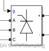
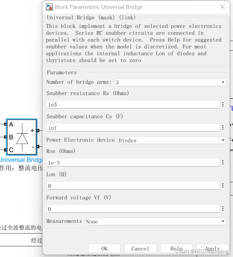
Connect the three-way bridge on the right (Bridge: Bridge - Sogou Encyclopedia (sogou.com) ), use thyristors, and select the default parameters:
The output on the right is direct current. Right into the reactance. Function: Smooth wave ( smoothing reactor_Baidu Encyclopedia (baidu.com) ):

Introduce a DC motor and adjust relevant parameters; introduce a controllable DC source; introduce a load:

At this point, the circuit part is completed, and then the control end is built.
The control end requires a phase-locked loop (PLL) and a pulse generator.
Phase locked loop (radio term)_Baidu Encyclopedia (baidu.com)
Where Phase Locked Loops Can Be Used This phase locked loop (PLL) system can be used to synchronize a set of variable frequency, three-phase sinusoidal signals. Used to detect initial phase, position, etc. The freq port of the phase-locked loop is not needed, just connect it to the terminal port (Terminator).
Pulse generator: Pulse width set to 5.

As shown in the figure above, the alpha port is connected to the conduction angle (constant module is enough), and the value is (0~90). At this time, the motor speed can be changed by adjusting the conduction angle and load, and the open-loop control model has been built.
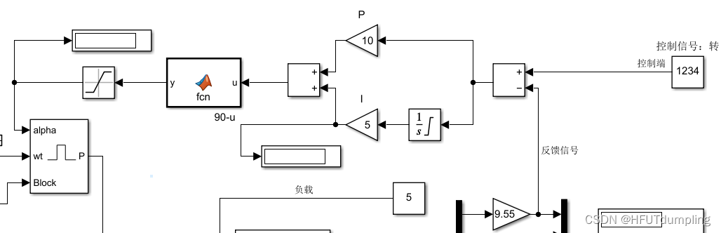
Introduce negative feedback to close the loop of the entire system. The control method is PI.
Among them, the construction method of PID control can refer to: (17 messages) [Learning record] PID principle learning and PID tuning in matlab/simulink_HFUTdumpling Blog-CSDN Blog
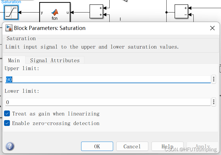
The signal output in fcn may exceed the limit, so a protection link Saturation needs to be added to limit the output. The upper limit is 90 and the lower limit is 0 (conduction angle).
In the PID controller, it is recommended not to directly refer to the intergrator module in the I link, because the overshoot may be too large and cause divergence, so the saturated integral link is used for insurance:
Finally, by adjusting the P and I values, a DC motor closed-loop speed regulation system with a net difference of 0 can be completed.
PWM speed control system

The above is the DC motor PWM closed-loop speed regulation system built by the author.
The motor end and power end modules of the entire system are similar to those used in the previous VM speed control system, so they will not be described again here.
In PWM speed regulation, there is no need to control the rectifier bridge, so full-wave rectification can be used ( what is a full-wave rectifier circuit? How to build a full-wave rectifier circuit? This article will help you summarize - Zhihu (zhihu.com) ) :
Just change the Thyristors in the Universal Bridge module to Diodes
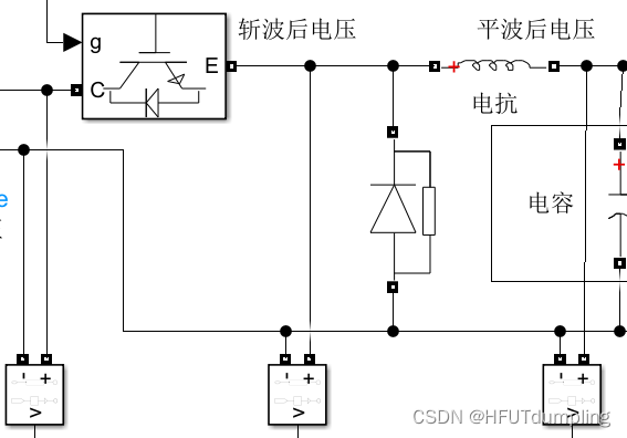
Introduce Buck circuit into the DC motor part: BUCK circuit_Baidu Encyclopedia (baidu.com)
First, IGBT is introduced ( IGBT_Baidu Encyclopedia (baidu.com) ), here as an ideal switch;
Introduce diodes and increase reactance and capacitance.
Here, the voltage is chopped, smoothed and stabilized respectively.
Chopping_Baidu Encyclopedia (baidu.com)
Smoothing reactor_Baidu Encyclopedia (baidu.com)
Control end: directly introduce PWM generator (PWM Generator (DC-DC))
The larger the duty cycle, the higher the speed, the smaller the duty cycle, the lower the speed.
After connecting to the PI control link and adjusting the P and I values, the DC motor PWM speed control system is completed. The actual speed of the motor can be controlled by adjusting the target speed.
Generate PWM wave using 555 timer

Summarize
As a non-electrical major student, it is really difficult to get into contact with things like power electronics simulation. In the next study, I still need to study more and supplement basic knowledge! Finally, I would like to thank Teacher Weiguang from station b for the tutorial video: Youying Shiguang’s personal space_bilibili_bilibili
References to this article:
1. [Tutorial] simulink 05 DC motor VM speed control system_bilibili_bilibili
2. [Tutorial] simulink 07 DC motor PWM open-loop speed control system_bilibili_bilibili
3. [Tutorial] simulink 08 DC motor PWM closed-loop speed control system_bilibili_bilibili
4. [Tutorial] simulink 06 Use 555 timer to generate PWM wave_bilibili_bilibili