Mini2440 doing recently in the use of development, a lot of online tutorials and practice is not consistent, leading to a long entry takes time. After finishing, the current approach has led lights lit mini2440, keil mdk, linux environment compiler, use minitools download.
mini2440 nor flash and nand flash into two kinds, generally less than 4k runs natively, the program needs to be greater than 4K pre-loaded boot program, copying from the storage location to the memory. Here it says exactly how mini2440 lighting led lights.
Method One: Use keil mdk way, first download MDK, the keil contain s3c2440 chip. According to the chip to create a project, add S3C2440.S file. After the project is created, written led.c file code is as follows


#define      rGPBCON     (*(volatile unsigned long *)0x56000010)
#define      rGPBDAT    (*(volatile unsigned long *)0x56000014)
#define      rGPBUP     (*(volatile unsigned long *)0x56000018)

#define GPB5_IN ~(3<<10)
#define GPB6_IN ~(3<<12)
#define GPB7_IN ~(3<<14)
#define GPB8_IN ~(3<<16)

#define GPB5_OUT (1<<10)
#define GPB6_OUT (1<<12)
#define GPB7_OUT (1<<14)
#define GPB8_OUT (1<<16)

#define LED1_ON ~(1<<5)
#define LED2_ON ~(1<<6)
#define LED3_ON ~(1<<7)
#define LED4_ON ~(1<<8)

#define LED1_OFF (1<<5)
#define LED2_OFF (1<<6)
#define LED3_OFF (1<<7)
#define LED4_OFF (1<<8)

void Led_Port_Init(void);
void Delay(int tt);

void main()
{
Led_Port_Init();

rGPBDAT |= (LED1_OFF|LED2_OFF|LED3_OFF|LED4_OFF);
rGPBDAT |= (LED1_OFF|LED2_OFF|LED3_OFF|LED4_OFF);

while(1)
{
    rGPBDAT = rGPBDAT&(LED1_ON);
    Delay(10);
    rGPBDAT = rGPBDAT|((LED1_OFF)|(LED2_OFF)|(LED3_OFF)|(LED4_OFF));
    Delay(10);
    rGPBDAT = rGPBDAT&(LED2_ON);
    Delay(10);
    rGPBDAT = rGPBDAT|((LED1_OFF)|(LED2_OFF)|(LED3_OFF)|(LED4_OFF));
    Delay(10);

    rGPBDAT = rGPBDAT&(LED3_ON);
    Delay(10);
    rGPBDAT = rGPBDAT|((LED1_OFF)|(LED2_OFF)|(LED3_OFF)|(LED4_OFF));
    Delay(10);

    rGPBDAT = rGPBDAT&(LED4_ON);
    Delay(10);
    rGPBDAT = rGPBDAT|((LED1_OFF)|(LED2_OFF)|(LED3_OFF)|(LED4_OFF));
    Delay(10);
    }
}

void Led_Port_Init(void)
{
rGPBCON &= ~((3<<10)|(3<<12)|(3<<14)|(3<<16));
rGPBCON |= (1<<10)|(1<<12)|(1<<14)|(1<<16);
}

void Delay(int tt)
{
int a,b;
for(a=0;a<=tt;a++)
for(b=0;b<=10000;b++);
}
When you're finished entering the key is to choose a good configuration interface. (It should be noted that the Keil MDK Nor Flash support and emulation download status, nand flash method currently not find the download)
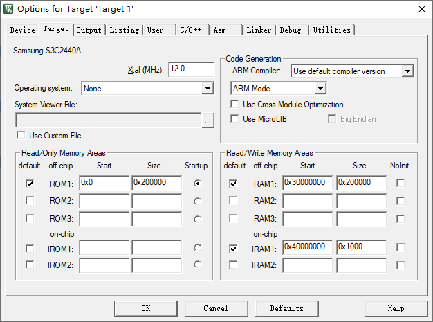
Configuration FIG. 1
Change target interface is provided as shown in FIG. 1, it can be seen from the configuration interface, program copy the ROM space, space is 2M. The power to run the chip size of the program copied to the RAM address space 0x30000000 runs is 2M.
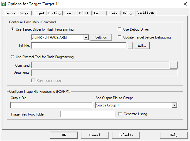
2 Select Driver FIG programming J-LINK / J-TRACE ARM
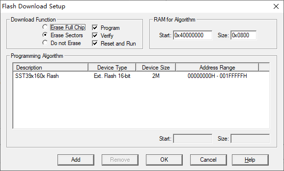
FIG 3 flash programming function is arranged Jlink
2 and 3, the configuration programming function of the target chip, chip select application nor flash. Use Target Driver check, cancel Use debug driver and Upadate Target option is selected.
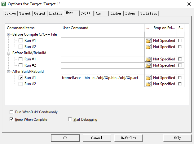
3 target compiler to generate bin file
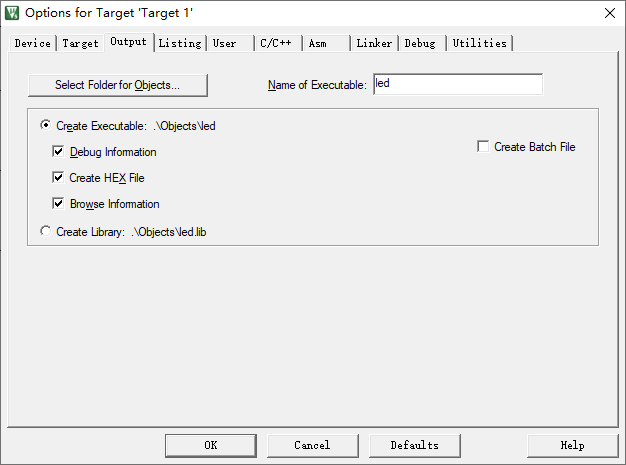
FIG 4 generates check HEX File
Other interfaces 3, 4 shown in FIG.
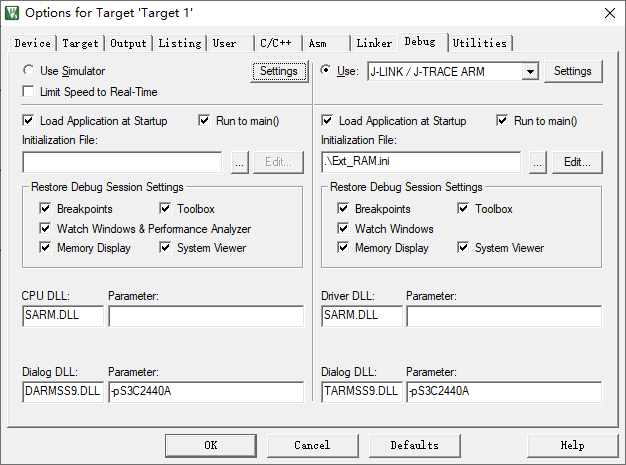
FIG 5 is provided Ext_RAM.ini
设置完成后,编译程序,点击Load下载目标程序。下载目标前注意图5Ext_RAM.ini中的设置。函数设置如下:
/******************************************************************************/
/* Ext_RAM.INI: External RAM (SDRAM) Initialization File                      */
/******************************************************************************/
// <<< Use Configuration Wizard in Context Menu >>>                           //
/******************************************************************************/
/* This file is part of the uVision/ARM development tools.                    */
/* Copyright (c) 2005-2008 Keil Software. All rights reserved.                */
/* This software may only be used under the terms of a valid, current,        */
/* end user licence from KEIL for a compatible version of KEIL software       */
/* development tools. Nothing else gives you the right to use this software.  */
/******************************************************************************/


0x200000

FUNC void Init (void) {

  _WDWORD(0x4A000008, 0xFFFFFFFF);      // Disable All Interrupts

  _WDWORD(0x53000000, 0x00000000);      // Disable Watchdog Timer

                                        // Clock Setup
                                        // FCLK = 300 MHz, HCLK = 100 MHz, PCLK = 50 MHz
  _WDWORD(0x4C000000, 0x0FFF0FFF);      // LOCKTIME
  _WDWORD(0x4C000014, 0x0000000F);      // CLKDIVN
  _WDWORD(0x4C000004, 0x00043011);      // MPLLCON
  _WDWORD(0x4C000008, 0x00038021);      // UPLLCON
  _WDWORD(0x4C00000C, 0x001FFFF0);      // CLKCON

                                        // Memory Controller Setup for SDRAM
  _WDWORD(0x48000000, 0x22000000);      // BWSCON
  _WDWORD(0x4800001C, 0x00018005);      // BANKCON6
  _WDWORD(0x48000020, 0x00018005);      // BANKCON7
  _WDWORD(0x48000024, 0x008404F3);      // REFRESH
  _WDWORD(0x48000028, 0x00000032);      // BANKSIZE
  _WDWORD(0x4800002C, 0x00000020);      // MRSRB6
  _WDWORD(0x48000030, 0x00000020);      // MRSRB7

  _WDWORD(0x56000000, 0x000003FF);      // GPACON: Enable Address lines for SDRAM
}


// Reset chip with watchdog, because nRST line is routed on hardware in a way
// that it can not be pulled low with ULINK

_WDWORD(0x40000000, 0xEAFFFFFE);        // Load RAM addr 0 with branch to itself
CPSR = 0x000000D3;                      // Disable interrupts
//CPSR = 0x00000063;                      // Disable interrupts
PC   = 0x40000000;                      // Position PC to start of RAM
_WDWORD(0x53000000, 0x00000021);        // Enable Watchdog
g, 0                                    // Wait for Watchdog to reset chip

Init();                                 // Initialize memory
LOAD obj\led.axf INCREMENTAL         // Download program
PC = 0x30000000;                       // Setup for Running

g, main                                 // Goto Main
注意修改该行代码与当前工程生成文件名一致,LOAD obj\led.axf INCREMENTAL // Download program