A general network architecture NB
NB-IoT end system architecture as shown below:
Terminal: UE (User Equipment), to the base station (eNodeB (evolved Node B, E -UTRAN base station)) through an air interface.
Wireless network side: two modes comprising a radio access network is a monolithic (Singel RAN), including a 2G / 3G / 4G wireless network and NB-IoT, and the other is a new NB-IoT. Is mainly responsible for air interface access process, residential management related functions, and is connected via S1-lite IoT core network interface to forward data to the non-access stratum level processing network element.
Core network: EPC (Evolved Packet Core), assume the function of the terminal is the non-access stratum interaction and forwards the data traffic to IoT IoT platform for processing. Overview is not comprehensive, detailed below.
Platform: telecommunications platform currently based.
Application Server: telecommunications platform, for example, the application server via http / https protocol and communications platform, to control the device by calling the open API platform, the platform device reports data pushed to the application server. Support equipment data and internet protocol analysis, converted into a standard data format json.
Second network structure refinement
2.1 a block diagram showing
an upper portion of FIG EPC refinement, is as follows:
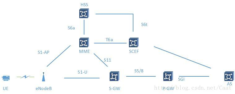
MME: Mobility Management, a mobility management entity (a signaling entity), the access key control-node network. Responsible for tracking and paging control idle mode UE. By the HSS (Home Subscribe Server, Home Subscriber Server) exchange of information, complete the user authentication.
SCEF: Service Cability Exposure Function, service capabilities open unit for additional network elements, control plane data transmission support for the new PDN type Non-IP's.
S-GW: Serving GW, serving gateway, the user is responsible for routing data packets and forwards. For idle state UE, S-GW is the end point of the downlink data path and triggers paging when downlink data arrives at the UE.
P-GW: Packet Data Network gateway , PDN gateway (Packet Data Network Gateway) is provided with an interface transmitting UE external packet data network connection point for uplink and downlink service level billing service.
2.2 part of the interface explained
X2 interface to
the X2 interface is used between the eNodeB and the eNodeB then implement signaling and data interaction. In the NB-IoT systems, X2 interface based on the R13 version does not support the user plane operation between eNodeB, the main control plane base station introduces a new cross user context recovery processing. Under optimized transport protocol user plane, suspended terminal moves to a new base station to initiate an RRC connection recovery procedure, carries the ID recovery from the old base station previously obtained, the new base station and then the X2 interface to the old base station initiates a user context acquisition process is acquired from the old base station user context information stored in the terminal when the old base station suspended to the UE on the new base station fast recovery.
S1 interface
The control plane of the S1 interface to achieve transmission of signaling between the eNodeB and the MME, a user plane to the user plane of the S1 interface to realize data transmission between eNodeB and the SGW. In the NB-IoT system, new features introduced by the S1 interface including: a radio access technology (RAT) type report (NB-IoT distinguish E-TURAN or access), the UE radio capability indication (e.g., by allowing MME downlink NAS transfer message sent to the eNodeB user equipment (UE) wireless capabilities), supporting control plane signaling process optimization to optimize the transmission scheme, and to optimize the transmission scheme for the user plane in the S1 interface into the connection suspend and resume processing. (This paragraph refer to: NB-IOT Status and Development System)
three transmission mode.
First, the transmission content, the three types of data may be transmitted: IP, Non-IP, SMS ( short message).
Since the number of terminals in a single-cell NB-IoT much larger than the number of LTE terminals, thus establishing and releasing a control plane is much greater than the number of LTE, for example, RCC connection establishment, release and the like; the other hand, in order to transmit and receive few bytes of data terminal enters the network signaling overhead consumed by the connected state from the idle state of the data payload is much larger than itself; in addition, based on complex signaling process LTE / EPC, energy consumption of the terminal as well as challenges.
Therefore, from this system architecture level, the control plane and the user plane needs to be done to enhance the efficiency and optimization of NB-IoT. NB-IoT will now be divided into two transmission optimization scheme, the transmission control plane and user plane transmission optimization optimization scheme, will be described separately.
Note: the user plane and control plane, simple to understand: the main control plane signaling radio bearer, the UE accesses responsible for resource allocation and the like; primary user plane carries user data.
3.1 Control plane transmission
control plane data transmission scheme for a small data transfer is optimized to support IP packet, non-IP packets or SMS encapsulated PDU for transmission, without creating between the DRB (radio bearer) and a base station and the S-GW S1-U bearers.
When the control plane transmission scheme, packet data transmission path to the MME with the NAS signaling, and S11-U by establishing connection between the S-GW, the completion of transmission of packet data between the MME and the S-GW. When the SGW receive downlink data, if S11-U connection exists, SGW downlink data to the MME, otherwise trigger the MME to perform paging.
Here come under the control of two transmission paths plane transmission scheme:
the UE - an eNodeB - the MME - S-GW - P-GW
the UE - an eNodeB - the MME - the SCEF
3.2 user plane transmission
By suspending the user plane transmission process and recovery process of redefining the user to quickly restore the idle state to the connected state, the air interface resource and reduce the associated signaling overhead. When the terminal enters an idle mode from connected state, eNodeB, the core network information temporary suspend the terminal AS, an S1AP bearer context and related information, the terminal information storage AS, an S1AP MME context and the bearer-related information stored in the terminal, the data transfer fast recovery, the need to re-establish and re-negotiation bearer security information.
On the other hand, small data packets directly transmitted through the user plane, it is necessary to establish S1-U and DRB.
3.3 flow diagram
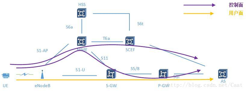
Note 1: MME - SCEF for the transmission of control plane Non-IP mode, the tariff rule be required to reconfigure this mode. Non-IP control plane or the data may be transmitted through the data plane PGW, the need to establish a tunnel PtP interface SGi.
Note 2: The user plane communication of data flow schematically, and the RRC connection is established by signaling pending MME-SGW-PGW, after writing a specific signaling process.