The following are the harvest of Chapter IV:
Protected Mode
What is Protected Mode? Direct definition of protected mode seems to be a very abstract thing, we might as well take a look at why we need protection mode and protected mode can do for us?
Protected Mode is relative to the real mode, and to solve some of the problems real mode of their argument. Addressing mode is a real mode under 8086CPU, usage instructions, a register size.
So what is the real-mode problem? Why do we need protection model?
Why do we need protection mode
① real mode, user processes and system processes belong to the same privilege level, on an equal footing, what can invoke system processes, what the user will be able to process calls.
② under real mode, accessed directly address the process is the physical address, to modify the contents of memory which is very easy, with no restrictions.
③ the real mode, the segment base can be modified freely, all memory access.
The above three points are security issues, is also a major problem. We can see from the "protection" of protected mode, the program running in protected mode will be more secure, more "security" will not be free to modify another program.
④ access memory, need to constantly changing segment base to access a memory address we want, because the size of a segment of only 64KB.
⑤ memory size is only 1M, enough.
⑥ can run only one program, a waste of CPU resources.
④ to ⑥ point is the question of use, if we think about computers still use CPU usage pattern in really, then, how low efficiency of the program will have to access the memory had to tie themselves up, but also to run a program and other program running on a complete, modern operating system is apparently unthinkable.
Here's to think how to solve these problems, the first ① point, we give each process is not the same privilege level is like, the operating system is clearly the highest level, the user process will be lower, the specific content will see after chapter .
The first point ②, protected mode uses a tab to access the memory, the process of accessing the address at this time is not the final physical address, but the virtual address. Also you need to convert a virtual address to a physical address through some final information in order to lower the paging mode. This also comes in later chapters.
For ②③ point, the most direct approach is to make certain restrictions on the reading and writing sections, CPU and operating system in the segment descriptors for this purpose. Descriptor, a configuration is described in section, the information comprising: a segment base address, segment limit, segment type, whether the segment can be written read, the direction of the segment (e.g., a stack extending to the low address, high address to the other extension )and many more. Specific details will talk later.
For the ④⑤ point, the development of the CPU 32, the address bus and data bus 32 to expand, also extended to the size of the general purpose registers 32, so that the child can access the memory address space suddenly becomes 4G, more convenient simply relying on a general-purpose register can access all memory addresses, and even without the segment base, and without left four. Of course, in order to be compatible, CPU in protected mode or using segments within the segment base address + offset address to access the final physical address, but we can do a little operation, the segment base is set to 0, alone in the segment offset address can access all of the physical memory, so this is also known as "flat mode." In addition, the CPU also expand the usage instructions, e.g. based addressing is no longer limited only by bx, sp as a base register, but all registers are through as a base register; indexed addressing is no longer limited to only si, di as index registers, but in addition to all the general purpose registers other than sp can be used as index registers.
GDT
A segment descriptor describes a segment of the information, a specialized data structure holds a plurality of descriptor called "global descriptor table" is actually a preserved segment descriptor array. This clearly can not register holds the global descriptor table, you can only save in a bigger memory inside. However, with respect to memory and registers L1, L2 caches, etc., or a lot slower, so a dedicated CPU is called descriptor buffer to improve the efficiency of the segment descriptor acquired by the used segment descriptors stored into the register, then when then taken out from the register, to reduce memory accesses, thus speeding up memory addressing.
Let's describe the descriptor structure:
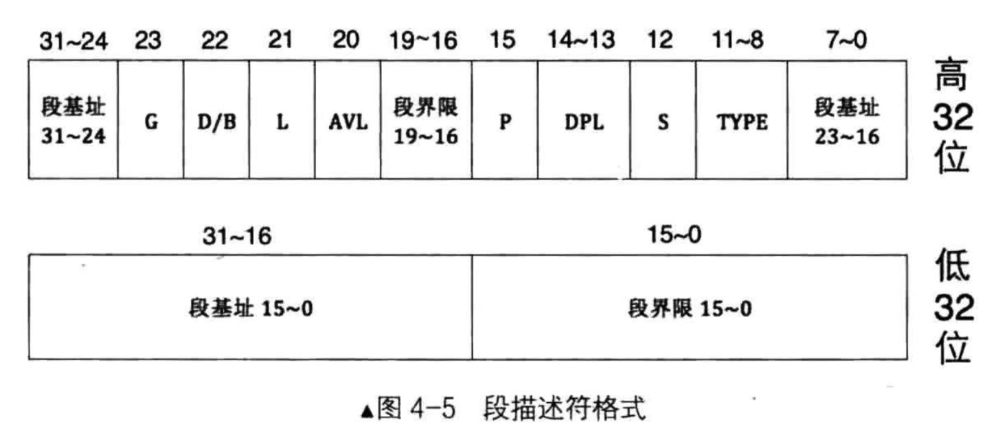
Low 32 bits 0 to 15 and 32 to 19 bits of 16 bits represent the block boundaries, to achieve a described segment boundary. Specific binding to a boundary value of 23 view G, G = 1, represents a segment limit particle size is 4KB, G = 0, it indicates that the particle size is 1Byte segment limit, the actual segment limit = (descriptor segment boundaries +1) * -1 segment limit grain size.
Low 32 16 to 31 32-bit high and 0 to 7 and 24 to 31 collectively describe the 32-bit segment base, why would disperse in three places? The answer is simple, compatibility issues, in order to expand the segment base 32, segment limit extended to 20, only then add in the back, so will be scattered in different places.
S represents a segment is a system segment or segments, in the eyes of CPU, any hardware to use something called a system, all software to use something called data. Therefore code segments, data segments, and the like also belong to the stack segment data segment S as represented.
Type Type specified period, a total of four. Only S decided, Type only its meaning. The figure is Type in the system and data segments in different meanings.
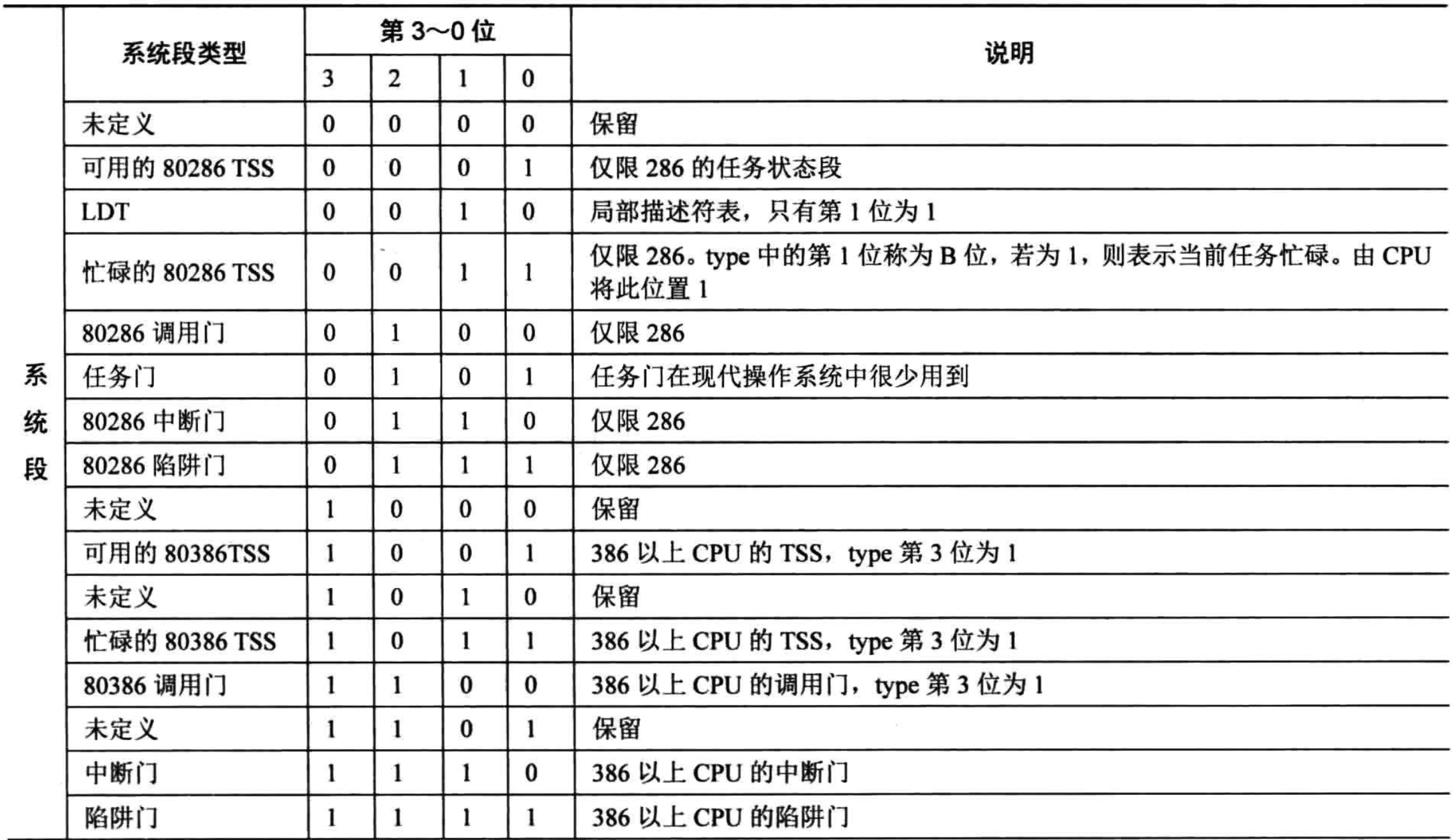

We mainly look at the significance Type of data segments. When a segment is a code segment, Type of X, R, C, A, representing the executability, and is readable, it is the same, whether the visited. When Dan segment, Type of X, W, E, A, representing the executability, and is writable, propagation direction, whether accessed.
What a privilege level segment DPL representatives belong.
P represents the presence or absence of the memory segment, segment 0 = absent, 1 represents a segment exists.
Available on behalf of AVL-bit operating systems are free to use, no special meaning.
L represents a 64-bit code segment or 32-bit.
D / B. For this bit is a code segment D, the code segments used to specify whether to use 16-bit or 32-bit effective addresses and operands. This bit is for the stack segment be B, used to specify the use of the stack segment register or esp sp register addressing range sp register is 0xFFFF, esp register addressing range is 0xFFFFFFFF.
G representing chapter boundaries particle size is 4KB or 1B.
Global descriptor indicates a common, multiple programs can define their own in the descriptor table. We enter a protection mode in which one of the steps is to load global descriptor table, let the CPU know the global symbol table describing the location, when the operation of memory, CPU will check the information of descriptors This operation is valid.
A20 address line
在实模式下,A20地址线是默认禁用的,原因是还未进入保护模式之前,地址总线还是要模拟20位的效果,即只保留20位以内的地址,如果地址超过20位,地址就会回绕到0,将地址20位(从0开始算)舍弃,所以要将A20地址线给禁用掉。但进入保护模式后,我们需要恢复地址总线的原貌,即使地址超过20位,地址也不应该回绕到0,所以此时将A20地址线打开,我们就能访问超过20位的地址了。因此,打开A20地址线,是进入保护模式的步骤之一。
CR0的PE位
进入保护模式的最后一个步骤是,打开CR0的PE位,CR0是控制寄存器。控制寄存器是CPU的窗口,它既可以展示CPU的内部状态,也可以控制CPU的运行机制。CR0的第0位,PE位,就是保护模式的开关,我们打开PE位,就是告诉CPU接下来我们要进入保护模式。
进入保护模式
由上面可以知道,进入保护模式的步骤如下:
① 打开A20地址线
② 加载GDT
③ 将CR0的PE位置为1
下面我们开始编写代码:
首先是boot.inc文件的改动,主要定义了描述符的各个位,方便设置整个段描述符。
LOADER_BASE_ADDR equ 0x900
LOADER_START_SECTOR equ 0x2

DESC_G_4K equ 1_000_000_000_000_000_000_000_00b
DESC_D_32 equ 1_000_000_000_000_000_000_000_0b
DESC_L    equ 0_000_000_000_000_000_000_000b

DESC_AVL  equ 0_000_000_000_000_000_000_00b
DESC_LIMIT_CODE2 equ 1111_0000_0000_0000_0000b
DESC_LIMIT_DATA2 equ DESC_LIMIT_CODE2
DESC_LIMIT_VIDEO2 equ 0000_000_000_000_000_000b
DESC_P equ 1_000_000_000_000_000b
DESC_DPL_0 equ 00_000_000_000_000_0b
DESC_DPL_1 equ 01_000_000_000_000_0b
DESC_DPL_2 equ 10_000_000_000_000_0b
DESC_DPL_3 equ 11_000_000_000_000_0b
DESC_S_CODE equ 1_000_000_000_000b
DESC_S_DATA equ DESC_S_CODE
DESC_S_sys  equ 0_000_000_000_000b
DESC_TYPE_CODE equ 1000_0000_0000b
DESC_TYPE_DATA equ 0010_0000_0000b

DESC_CODE_HIGH4 equ (0x00 << 24) + DESC_G_4K + DESC_D_32 + \
DESC_L + DESC_AVL + DESC_LIMIT_CODE2 + \
DESC_P + DESC_DPL_0 + DESC_S_CODE + \
DESC_TYPE_CODE + 0x00

DESC_DATA_HIGH4 equ (0x00 << 24) + DESC_G_4K + DESC_D_32 + \
DESC_L + DESC_AVL + DESC_LIMIT_DATA2 + \
DESC_P + DESC_DPL_0 + DESC_S_DATA + \
DESC_TYPE_DATA + 0x00

DESC_VIDEO_HIGH4 equ (0x00 << 24) + DESC_G_4K + DESC_D_32 + \
DESC_L + DESC_AVL + DESC_LIMIT_VIDEO2 + DESC_P + \
DESC_DPL_0 + DESC_S_DATA + DESC_TYPE_DATA + 0x0b

RPL0 equ 00b
RPL1 equ 01b
RPL2 equ 10b
RPL3 equ 11b
TI_GDT equ 000b
TI_LDT equ 100b
下面是loader.S的改动:
%include "boot.inc"
section loader vstart=LOADER_BASE_ADDR
LOADER_STACK_TOP equ LOADER_BASE_ADDR
jmp loader_start
;构建GDT,设置段描述符
;第一个段描述符不作使用
GDT_BASE: dd 0x0000_0000
          dd 0x0000_0000
;代码段描述符
CODE_DESC: dd 0x0000FFFF
           dd DESC_CODE_HIGH4
;数据段、栈段描述符
DATA_STACK_DESC: dd 0x0000FFFF
                 dd DESC_DATA_HIGH4
;显存段
VIDEO_DESC: dd 0x8000_0007
            dd DESC_VIDEO_HIGH4

GDT_SIZE equ $ - GDT_BASE
GDT_LIMIT equ GDT_SIZE - 1
;预留60个描述符
times 60 dq 0
;设置各个选择子
SELECTOR_CODE equ (0x0001 << 3) + TI_GDT + RPL0
SELECTOR_DATA equ (0x0002 << 3) + TI_GDT + RPL0
SELECTOR_VIDEO equ (0x0003 << 3) + TI_GDT + RPL0
;用于设置GDTR寄存器的值
gdt_ptr dw GDT_LIMIT
        dd GDT_BASE
loadermsg db '2 loader in real.'
loader_start:

mov sp,LOADER_BASE_ADDR
mov bp, loadermsg
mov cx, 17
mov ax, 0x1301
mov bx, 0x001f
mov dx, 0x1800
int 0x10

in al,0x92
or al,0000_0010b
out 0x92,al
;进入保护模式的三个步骤
lgdt [gdt_ptr]

mov eax, cr0
or eax, 0x0000_0001
mov cr0, eax
;刷新流水线
jmp dword SELECTOR_CODE:p_mode_start

[bits 32]
p_mode_start:
mov ax, SELECTOR_DATA
mov ds, ax
mov es, ax
mov ss, ax
mov esp, LOADER_STACK_TOP
mov ax, SELECTOR_VIDEO
mov gs, ax
mov byte [gs:160], 'P'

jmp $
像之前一节那样编译及加载程序到硬盘后,执行bochs,第二行会显示字符P,最后一行会显示“2 loader in real",结果如下:
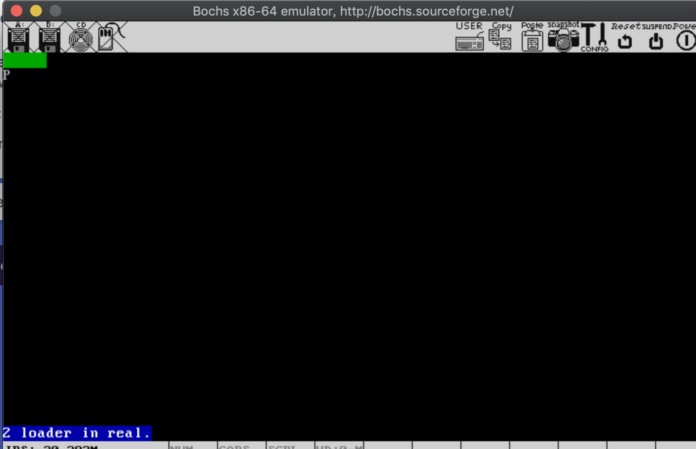
另一个值得注意的指令是:jmp dword SELECTOR_CODE:p_mode_start,这个指令是用来刷新流水线的,因为在进入保护模式之前,p_mode_start后面的指令也会被放上流水线,指令会按照16位译码,其实本来应该按照32位译码才能正常执行,所以我们需要清除流水线上的这些指令,保证这些指令按32位译码,这样才能正常地运行下去。