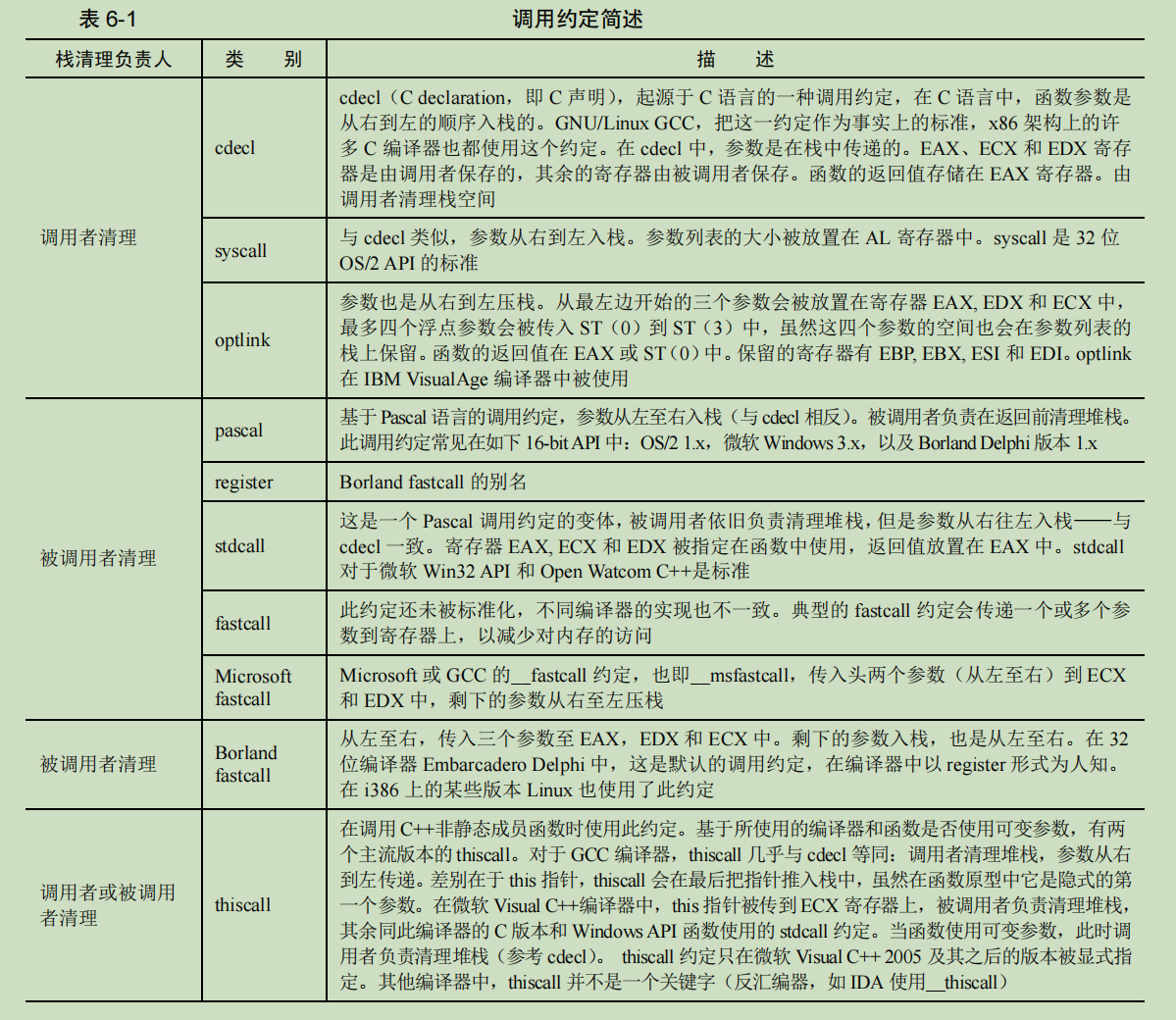
1. Introduction to function calling convention
Calling conventions, calling conventions, literally, it is a set of conventions when calling a function, it is the interface of the called code, it is reflected in:
- The way to pass parameters is to put them in registers? stack? Or a mix of both?
- The order in which parameters are passed is from left to right? Or right to left?
- Is the register environment caller-saved, or callee-saved? Which registers are saved?
2. Implement your own printing function
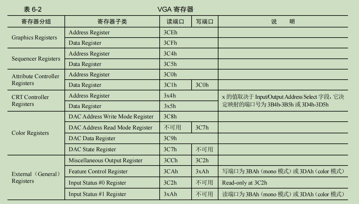
1. Port control of graphics card
-
The first four groups of registers belong to groups. The reason for the grouping of registers is that there are too many registers on the graphics card and the system ports are limited. Therefore, the method of operating this type of register is to first specify the index value of the register in the Address Register to determine which register is being operated, and then perform read and write operations on the indexed register in the Data Register register.
-
The port addresses of Address Register and Data Register in the above CRT Controller Registers register group are somewhat special. Its port address is not fixed, and the specific value depends on the Input/Output Address Select field in the Miscellaneous Output Register register.
-
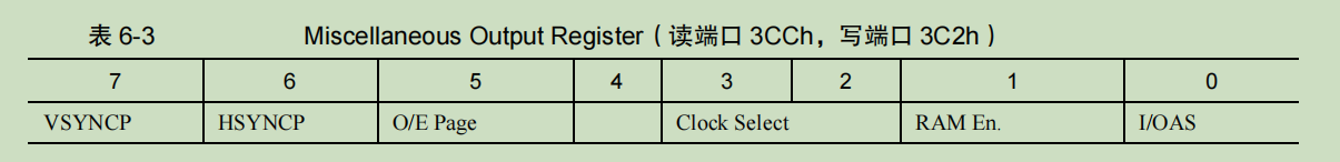
I/OAS (Input/Output Address Select), this bit is used to select the address of the CRT controller register group, here refers to the address of Address Register and Data Register.
-
When this bit is 0: and for compatibility with monochrome adapters (graphics cards), the port address of the Input Status #1 Register is set to 0x3BA
-
When this bit is 1: and for compatibility with color/graphics adapters (graphics cards), the port address of the Input Status #1Register register is set to 0x3DA
The write port of the Feature Control register register is also in the form of 3xAh, and the value of the port address is affected by the I/OAS bit in the same way.
- If the I/OAS bit is 0, the write port address is 3BAh.
- If the I/OAS bit is 1, the write port address is 3DAh.
By default, the value of the Miscellaneous Output Register register is 0x67, and other fields are ignored. We only pay attention to the most important I/OAS bit, and its value is 1. That is to say:
- The port address of the Address Register of the CRT controller register group is 0x3D4, and the port address of the Data Register is 0x3D5
- The port address of the Input Status #1Register register is set to 0x3DA.
- The write port of the Feature Control register is 0x3DA.
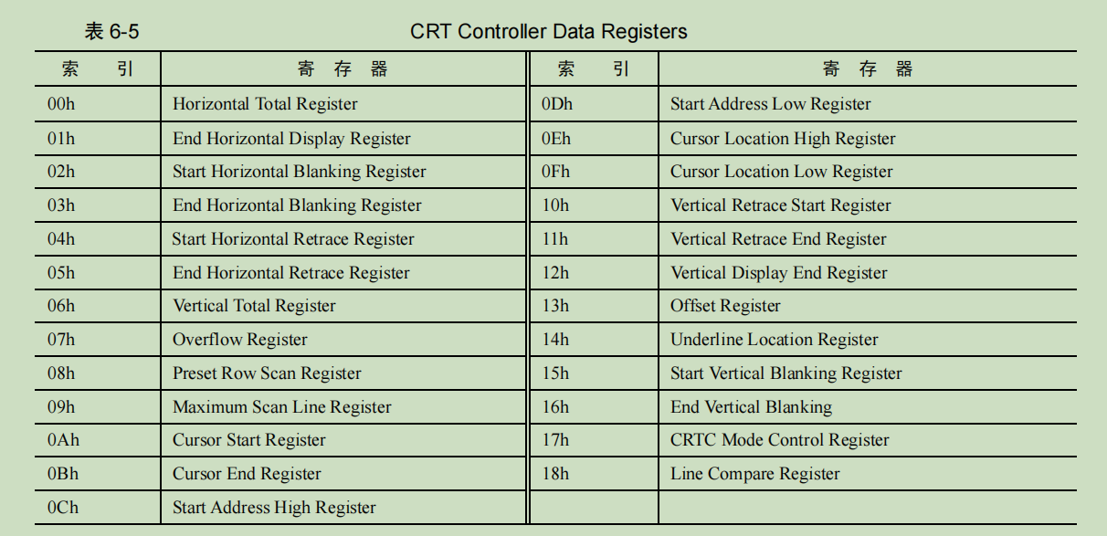
| index | register name | Function |
|---|---|---|
| 00h | Horizontal Total Register | Horizontal total register, which defines the total number of pixels required for a complete horizontal scan line |
| 01h | End Horizontal Display Register | The horizontal display end register defines the width of the display area, that is, the number of pixels visible on a horizontal scan line |
| 02h | Start Horizontal Blanking Register | Horizontal blanking start register, which defines the starting pixel position of horizontal blanking |
| 03h | End Horizontal Blanking Register | Horizontal blanking end register, which defines the end pixel position of horizontal blanking |
| 04h | Start Horizontal Retrace Register | Horizontal retrace start register, which defines the starting pixel position of horizontal retrace |
| 05h | End Horizontal Retrace Register | Horizontal retrace end register, which defines the end pixel position of horizontal retrace |
| 06h | Vertical Total Register | Vertical total register, which defines the total number of lines required for a complete vertical scan line |
| 07h | Overflow Register | The overflow register defines the number of lines that exceed the range of the total number of vertical lines during vertical retrace |
| 08h | Preset Row Scan Register | Preset line scan register, which defines the initial scan line of the display |
| 09h | Maximum Scan Line Register | The maximum number of scan lines register defines the maximum number of lines on each horizontal scan line |
| 0Ah | Cursor Start Register | Cursor start register, which defines the starting line displayed by the cursor |
| 0Bh | Cursor End Register | Cursor end register, which defines the end line displayed by the cursor |
| 0Ch | Start Address High Register | Start address high register, which defines the high 8 bits of the start address of the display area |
| 0Dh | Start Address Low Register | Start address low register, which defines the lower 8 bits of the start address of the display area |
| 0Eh | Cursor Location High Register | Cursor position high register, which defines the high 8 bits of the cursor position |
| 0 Fh | Cursor Location Low Register | Cursor position low register, defines the lower 8 bits of the cursor position |
| 10h | Vertical Retrace Start Register | Vertical retrace start register, which defines the starting line number of vertical retrace |
| 11h | Vertical Retrace End Register | Vertical retrace end register, which defines the end line number of vertical retrace |
| 12h | Vertical Display End Register | Vertical display end register, which defines the end line number of vertical display |
| 1 p.m | Offset Register | Offset register, which defines the number of bytes each character occupies on the screen |
| 14h | Underline Location Register | The underline position register defines the position of the underline |
| 15h | Start Vertical Blanking Register | Vertical Blanking Start Register |
| 16h | End Vertical Blanking Register | Vertical blanking end register, which defines the end line number of vertical blanking |
| 17h | CRTC Mode Control Register | CRTC mode control register, which defines the mode and operation mode of the CRTC controller |
| 6 p.m | Line Compare Register | Line comparison register, which defines the comparison signal sent when the CRT controller scans a specific line, which can be used to generate interrupts or other operations |
Use C language to implement your own printing function
First specify the index value of the register in the Address Register to determine which register is being operated, and then perform read and write operations on the indexed register in the Data Register register.
Example:
;;;;;;;;;  获取当前光标位置 ;;;;;;;;;
   ;先获得高8位
   mov dx, 0x03d4  ;索引寄存器
   mov al, 0x0e	   ;用于提供光标位置的高8位
   out dx, al
   mov dx, 0x03d5  ;通过读写数据端口0x3d5来获得或设置光标位置
   in al, dx	   ;得到了光标位置的高8位
   mov ah, al

   ;再获取低8位
   mov dx, 0x03d4
   mov al, 0x0f
   out dx, al
   mov dx, 0x03d5
   in al, dx
There are 80 characters per line on the screen, 25 lines in total. Our scrolling implementation is relatively simple. Now let’s talk about the steps to realize scrolling with this solution: (1
) Move the contents of lines 1 to 24 to lines 0 to 23, That is to overwrite the data in row 0.
(2) Then cover the characters in the 24th line, which is the last line, with spaces so that it looks like a new blank line.
(3) Move the cursor to the 24th line, which is the beginning of the last line.
After these three steps, the screen is like scrolling up one line
print.c
#include "print.h"
#include "io.h"

//设置光标位置
void set_cursor(unsigned short cursor_pos);

//往显存写入字符。参数:显存位置,写入的字符
void write_char(unsigned short video_memory_pos,char ch);
//向下滚动一行
void roll_screen();


void put_str(char* str)
{


	while(*str != '\0')
	{


		put_char(*str);
		str++;
	}
}


void put_char(char ch)
{


//获取当前光标位置
	unsigned short cursor_pos=0;
//高8位
	unsigned char high_8=0;
	outb(0x03d4,0x0e);
	high_8 = inb(0x03d5);

//低8位
	unsigned char low_8=0;
	outb(0x03d4,0x0f);
	low_8 = inb(0x03d5);
	cursor_pos =(high_8<<8) + low_8;


	//如果是换行键或者回车键
	if(ch==0xd || ch==0xa )
	{


		cursor_pos=cursor_pos-(cursor_pos % 80)+80;  //光标值减去除80的余数便是取整
		if(cursor_pos<2000)
		{


			set_cursor(cursor_pos);
		}
		else
		{


			roll_screen();   //向下滚动一行

		}
	}
	//如果是退格键
	else if(ch==0x8)
	{


		//当为退格时,本质上只要将光标向前一个显存位置即可,后面再输入的字符自然会覆盖此字符
		//但有可能在键入退格后不再键入新的字符,这时在光标已经向前移动到待删除的字符位置,但字符还在原处
		//;这就显得好怪异,所以此处添加了空格或空字符0
		cursor_pos--;
		write_char(cursor_pos*2,0x20);
		set_cursor(cursor_pos);

	}
	//普通字符
	else
	{


		unsigned int video_memory_pos=cursor_pos*2;
		write_char(video_memory_pos,ch);
		cursor_pos++; 			//下一个光标值
		if(cursor_pos<2000)		//若光标值小于2000,表示未写到显存的最后,则去设置新的光标值
		{


			set_cursor(cursor_pos);
		}
		else
		{


			roll_screen();  //向下滚动一行
		}
	}
}


void put_int(unsigned int num)
{


	unsigned char put_int_buffer[9] = {

    0};
	char hex_digits[] = "0123456789ABCDEF";

	//32位数字中,16进制数字的位数是8个
	//遍历每一位16进制数字
	int i;
	for(i = 0; i<8; i++)
	{


		 hex_str[i] = hex_digits[ (num>>i*4) & 0x0000000F ];
	}
	put_str(put_int_buffer);


}


void set_cursor(unsigned short cursor_pos)
{


	//先设置高8位
	outb(0x03d4,0x0e);
	outb(0x03d5,(cursor_pos>>8));

	//先设置低8位
	outb(0x03d4,0x0f);
	outb(0x03d5,(cursor_pos&0b0000000011111111));


}

//参数:显存位置,写入的字符
void write_char(unsigned short video_memory_pos,char ch)
{


	asm volatile ("movb %b1, %%gs:(%%bx);\
		inc %%bx; \
		movb $0x7,%%gs:(%%bx); \
		"::"b"(video_memory_pos),"a"(ch));

}


void roll_screen()
{


	unsigned short cursor_pos;

	//一共有2000-80=1920个字符要搬运,共1920*2=3840字节.一次搬4字节,共3840/4=960次
	int *src  = (int*)0xb80a0;  //第1行行首
	int *dest = (int*)0xb8000;	//第0行行首
	int i;
	for(i = 0; i<960;i++)
	{


		*dest = *src;
		src++;
		dest++;
	}

	for(i = 3840; i<4000;i+=2)
	{


		write_char(i,0x20);			//最后一行填充空格
	}


	cursor_pos=1920;		//将光标值重置为1920,最后一行的首字符.

	set_cursor(cursor_pos);


}
print.h
#ifndef __LIB_KERNEL_PRINT_H
#define __LIB_KERNEL_PRINT_H
void put_char(unsigned char ch);
void put_str(char* str);
void put_int(unsigned int num);	 // 以16进制打印

#endif
Use the inline assembly knowledge
io.h in the next section in advance
/**************	 机器模式   ***************
	 b -- 输出寄存器QImode名称,即寄存器中的最低8位:[a-d]l。
	 w -- 输出寄存器HImode名称,即寄存器中2个字节的部分,如[a-d]x。

	 HImode
	     “Half-Integer”模式,表示一个两字节的整数。
	 QImode
	     “Quarter-Integer”模式,表示一个一字节的整数。
*******************************************/

#ifndef __LIB_IO_H
#define __LIB_IO_H

/* 向端口port写入一个字节*/
static inline void outb(unsigned short port,unsigned char data) {


/*********************************************************
 a表示用寄存器al或ax或eax,对端口指定N表示0~255, d表示用dx存储端口号,
 %b0表示对应al,%w1表示对应dx */
   asm volatile ( "outb %b0, %w1" : : "a" (data), "d" (port));
/******************************************************/
}

/* 将addr处起始的word_cnt个字写入端口port */
static inline void outsw(unsigned short port, void* addr,unsigned int word_cnt) {


/*********************************************************
   +表示此限制即做输入又做输出.
   outsw是把ds:esi处的16位的内容写入port端口, 我们在设置段描述符时,
   已经将ds,es,ss段的选择子都设置为相同的值了,此时不用担心数据错乱。*/
   asm volatile ("cld; rep outsw" : "+S" (addr), "+c" (word_cnt) : "d" (port));
/******************************************************/
}

/* 将从端口port读入的一个字节返回 */
static inline char inb(unsigned short port) {


   char data;
   asm volatile ("inb %w1, %b0" : "=a" (data) : "d" (port));
   return data;
}

/* 将从端口port读入的word_cnt个字写入addr */
static inline void insw(unsigned short port, void* addr, unsigned int word_cnt) {


/******************************************************
   insw是将从端口port处读入的16位内容写入es:edi指向的内存,
   我们在设置段描述符时, 已经将ds,es,ss段的选择子都设置为相同的值了,
   此时不用担心数据错乱。*/
   asm volatile ("cld; rep insw" : "+D" (addr), "+c" (word_cnt) : "d" (port) : "memory");
/******************************************************/
}

#endif
main.c
#include "print.h"
#include "io.h"

void main(void)
{


	put_str("hello world");
	put_char('\n');
	put_int(0x12345678);
	put_char('\n');
	put_int(0x123);
	while(1);
}
compile link
nasm -I /home/abc/Desktop/bochs/code/boot/ /home/abc/Desktop/bochs/code/boot/mbr.s -o /home/abc/Desktop/bochs/code/boot/mbr.bin
dd if=/home/abc/Desktop/bochs/code/boot/mbr.bin  of=/home/abc/Desktop/bochs/hd60m.img bs=512 count=1 conv=notrunc

nasm -I /home/abc/Desktop/bochs/code/boot/ /home/abc/Desktop/bochs/code/boot/loader.s -o /home/abc/Desktop/bochs/code/boot/loader.bin
dd if=/home/abc/Desktop/bochs/code/boot/loader.bin  of=/home/abc/Desktop/bochs/hd60m.img bs=512 count=4 seek=2 conv=notrunc

nasm -f elf32  ./code/lib/print.s -o  ./code/lib/print.o

gcc -I ./code/lib/ -m32 -c  ./code/kernel/main.c -o ./code/kernel/main.o

gcc  -I ./code/lib/ -m32 -c   ./code/kernel/test.c -o ./code/kernel/test.o

ld -m elf_i386 ./code/kernel/main.o ./code/lib/print.o  ./code/kernel/test.o -Ttext 0xc0001500 -e main -o ./code/kernel/kernel.bin

dd if=./code/kernel/kernel.bin of=/home/abc/Desktop/bochs/hd60m.img bs=512 count=200 seek=9 conv=notrunc

bin/bochs -f bochs.disk
Effect

What is inline assembly
- Inline assembly is called inline assembly, and GCC supports directly embedding assembly code in C code, so it is called GCC inline assembly. C language does not support register operations, but assembly language can, so it is natural to think of the way of embedding inline assembly in C language to improve "combat power". Through inline assembly, C programmers can realize functions that cannot be expressed in C language, so that The development capability has been greatly improved.
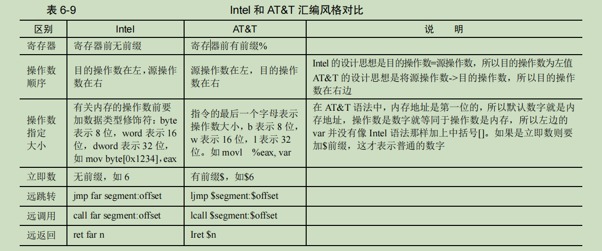
- Inline assembly is divided into two categories according to the format, one is the simplest basic inline assembly, and the other is more complex extended inline assembly. The assembly language used in inline assembly has the syntax of AT&T, not We are familiar with the Intel assembly syntax, GCC only supports it, so we have to understand AT&T.
basic inline assembly
Basic inline assembly, the simplest form of inlining, is of the form:
asm [volatile] ("assembly code")
-
asm: Used to declare inline assembly expressions, which is a fixed part of inline assembly and is indispensable. asm and __asm__ are the same, and are macros defined by gcc:
#define __asm__ asm. -
volatile: is optional, it tells gcc: "Don't modify the assembly code I wrote, please keep it as it is". Volatile is the same as __volatile__, a macro defined by gcc:
#define __volatile__ volatile -
"assembly code" is the assembly code we wrote, it must be in parentheses, and must be enclosed in double quotes. The rules are as follows:
- Instructions must be enclosed in double quotes, no matter whether there is one instruction or multiple instructions in the double quotes
- A pair of double quotes cannot span lines, if they need to be escaped with a backslash at the end
\. - Commands are separated by a semicolon followed by a
;newline\nor a newline and a\n \ttab. - When the instruction is in multiple double quotes, except for the last double quote, the code in the rest of the double quotes must have a delimiter at the end, such as:
asm(“movl $9,%eax;””pushl %eax”) 正确 asm(“movl $9,%eax””pushl %eax”) 错误 - Registers are prefixed with %, immediate values are prefixed with $, and the order of operands is from left to right.
Extended inline assembly
Format:
asm [volatile] (“assembly code”:output : input : clobber/modify)
-
output: It is used to specify how the data of the assembly code is output to the C code. After the embedded assembly instruction runs, if you want to store the running result in a C variable, use this item to specify the output location. The format of each operand in output is:
“操作数修饰符约束名”(C 变量名), and the operand modifier is usually an equal sign=. Multiple operands are,separated by commas. -
input: Used to specify how data in C is input to assembly. To let the assembly use variables in C as parameters, it must be specified here. The format of each operand in input is:
“[操作数修饰符] 约束名”(C 变量名), the operand modifier is optional. Multiple operands are,separated by commas. -
clobber/modify: After the assembly code is executed, some memory and register resources will be destroyed. Through this item, the compiler is notified that the register or memory data may be destroyed, so that gcc knows which registers or memory need to be protected in advance.
- Format: Enclose the register name with double quotes, and
,separate multiple registers with commas. There is no need to add two registers%%, just write the name, such as:asm("movl %%eax, %0;movl %%eax,%%ebx":"=m" (ret_value)::"bx") - If our inline assembly code modifies the flag bits in the flag register eflags, it also needs to be declared with "cc" in clobber/modify
- If we modify memory, we need to declare "memory" in clobber/modify.
- If we use memory constraints in output, gcc will naturally get which memory is modified. But if the modified content is not in the output, we need to use "memory" to tell gcc.
- Format: Enclose the register name with double quotes, and
- The role of constraints: The role of constraints is to make the operands of C codes into operands that can be used by assembly codes. All the constraints are actually used for assembly. Constraints are the mapping between operands in C language and operands in assembly language. He tells gcc how to change the identity of the same operand in two environments and how to connect and communicate. During the compilation process, the C code must first be converted into assembly code. The constraints in inline assembly are equivalent to gcc allowing us to specify the compiled form of data in C.
The following are explanations of the various constraints:
- Register constraint: register constraint is to ask gcc which register to use, and to constrain the input or output variable in a certain register. The common register constraints are: a:
indicates register eax/ax/al
b: indicates register ebx/bx/bl
c: Indicates register ecx/cx/cl
d: Indicates register edx/dx/dl
D: Indicates register edi/di
S: Indicates register esi/si
q: Indicates any one of these 4 general-purpose registers: eax/ebx/ecx/edx
r : Indicates any one of these six general-purpose registers: eax/ebx/ecx/edx/esi/edi
g: Indicates that it can be stored in any location (register and memory). Equivalent to the same as q, you can also let gcc arrange it in the memory
A: combine eax and edx into a 64-bit integer
f: represent the floating-point register
t: represent the first floating-point register
u: represent the second floating-point register register
#include<stdio.h>
void main()
{


	int in_a = 1, in_b = 2, out_sum;
	asm("addl %%ebx, %%eax":"=a"(out_sum):"a"(in_a),"b"(in_b));
	printf("sum is %d\n",out_sum);
}
-
Memory constraint: The memory constraint requires gcc to directly use the memory address of the C variable located in input and output as the operand of the inline assembly code, without the need for register transfer, and directly reads and writes the memory, that is, the operand of the assembly code is C pointer to the variable.
m: Indicates that the operand can use any memory form
o: The operand is a memory variable, but it is accessed in the form of offset, that is, the format including offset_address. -
Immediate constraint: Immediate is a constant. This constraint requires gcc not to pass memory and registers when passing values, but to pass them directly to assembly code as immediate. Since the immediate value is not a variable, it can only be used as an rvalue, so it can only be placed in input.
i: Indicates that the operand is an integer immediate number
F: Indicates that the operand is a floating-point immediate number
I: Indicates that the operand is an immediate number between 0 and 31
J: Indicates that the operand is an immediate number between 0 and 63
N: Indicates The operand is an immediate number between 0 and 255
O: indicates that the operand is an immediate number between 0 and 32
X: indicates that the operand is an immediate number of any type -
General constraints:
0~9: This constraint is only used in the input part, but it means that the nth operand in output and input can use the same register or memory.
serial number placeholder
-
Placeholders: In order to facilitate reference to operands, extended inline assembly provides placeholders, whose role is to represent operands (registers, memory, immediate data) specified by constraints, we are more inline assembly Use placeholders in to refer to operands. Placeholders are divided into serial number placeholders and name placeholders:
-
Serial number placeholder: The serial number placeholder is the operand in output and input, numbered from 0 to 9 according to their order from left to right, that is to say, up to 10 serial number placeholders are supported, reference Its format is %0~9. The operand represented by the placeholder is 32-bit data by default, insert the character 'h' between % and the sequence number to indicate that the operand is ah (8th to 15th), or insert the character 'b' to indicate the operation The number is al (bits 0 to 7).
h – The register name corresponding to the byte in the high part of the output register, such as ah, bh, ch, dh.
b – The name corresponding to the lower part of 1 byte in the output register, such as al, bl, cl, dl.
w – The part of the output register whose size is 2 bytes, such as ax, bx, cx, dx.
k – The four-byte portion of the output register, such as eax, ebx, ecx, edx.
For example:
asm("addl %%ebx, %%eax":"=a"(out_sum):"a"(in_a),"b"(in_b));
equivalent to
asm("addl %2, %1":"=a"(out_sum):"a"(in_a),"b"(in_b));
where:
"=a" (out_sum) serial number is 0, %0 corresponds to eax.
The serial number of "a" (in_a) is 1, %1 corresponds to eax.
The serial number of "b" (in_b) is 2, and %2 corresponds to ebx. -
Name placeholder: The name placeholder is different from the serial number placeholder. The serial number placeholder can be recognized by the compiler by its position in output and input. The name placeholder needs to explicitly name the operand in output and input, and it uses this format to identify the operand:
[名称]”约束名”(C 变量). In this way, the assembly operand corresponding to the constraint has a name, and when referring to the operand in the assembly code, the form of %[name] is sufficient.
-
-
Since the placeholders in extended inline assembly must have a prefix %, in order to distinguish between placeholders and registers, we have to use two % as prefixes in front of registers. This is what was explained earlier in this section. There are two reasons for the % prefix.
-
There are also operand type modifiers in the constraints, which are used to modify the constrained operands: memory, registers, and there are the following types in ouput and input respectively.
In output:
=: indicates that the operand is write-only, which is equivalent to assigning a value to the C variable in the output brackets, such as =a(c_var), this modifier is equivalent to c_var=eax.
+: Indicates that the operand is readable and writable, and tells gcc that the constrained register or memory is read first and then written.
&: Indicates that the operands in this output should exclusively occupy the constrained (allocated) registers, which are only used by output, and the allocated registers in any input cannot be the same. Note that when there are multiple modifiers in the expression, & must be next to the constraint name and cannot be separated.
In input:
%: The input in input can be interchanged with the next input operand -
In general, C variables in input are read-only, and C variables in output are write-only.
-
The modifier '=' is only used in output, indicating that the C variable is write-only, and its function is equivalent to the assembly operand of the C variable = constraint in output, such as "=a" (c_var), which is equivalent to the value of c_var=eax .
-
The modifier '+' is also only used in output, but it has read and write attributes, that is, it can be used as both input and output, so it is omitted to declare constraints in input.
#include <stdio.h>
void main()
{


	int in_a = 1, in_b = 2;
	asm("addl %%ebx, %%eax;":"+a"(in_a):"b"(in_b));
	printf("in_a is %d\n", in_a);
}
Introduction to Machine Mode of Extended Inline Assembly
- Machine modes are used to specify the size and format of data at the machine level.
- Since various constraints cannot exactly express the specific operand object, the machine mode is referenced to describe the size of the data object and its specified part from a finer granularity
Registers can be divided into several parts according to whether they can be used alone. Take eax as an example:
- One byte of the lower part: al
- One byte of the high part: ah
- Two-byte part: ax
- Four-byte part: eax
h : The register name corresponding to the byte in the high part of the output register, such as ah, bh, ch, dh.
b: The name corresponding to the lower part of 1 byte in the output register, such as al, bl, cl, dl.
w : The part corresponding to the size of 2 bytes in the output register, such as ax, bx, cx, dx.
k : The four-byte part of the output register, such as eax, ebx, ecx, edx.
Example:
1 #include<stdio.h>
2 void main()
3 {


4 	int in_a = 0x1234, in_b = 0;
5 	asm("movw %1, %0":"=m"(in_b):"a"(in_a));
6 	printf("in_b now is 0x%x\n", in_b);
}
The purpose of this code is to copy the lower 16 bits of in_a to in_b. In the fifth line, the constraint of the variable in_a is a, which means that gcc assigns the value of in_a to the register al, ax or eax, which is very vague. After all, gcc Who is the value of in_a assigned to? The subsequent movw instruction is also very vague, we can only understand it this way: the movw instruction copies 2 bytes in al, ax or eax to the memory where in_b is located
After modification:
1 #include<stdio.h>
2 void main()
3 {


4 	int in_a = 0x1234, in_b = 0;
5 	asm("movw %w1, %0":"=m"(in_b):"a"(in_a));
6 	printf("in_b now is 0x%x\n", in_b);
}
Add the w prefix to determine the source operand is ax