[TOC]
content
VLAN concepts and benefits
VLAN species
Static VLAN Configuration
Trunk Introduction and Configuration
Three switches forward principle
Three switches configuration
1.VLAN Overview and Benefits
Split broadcast domains, there are two methods, one is physically divided, using a router device, the other logical segmentation, i.e. divided by VLAN
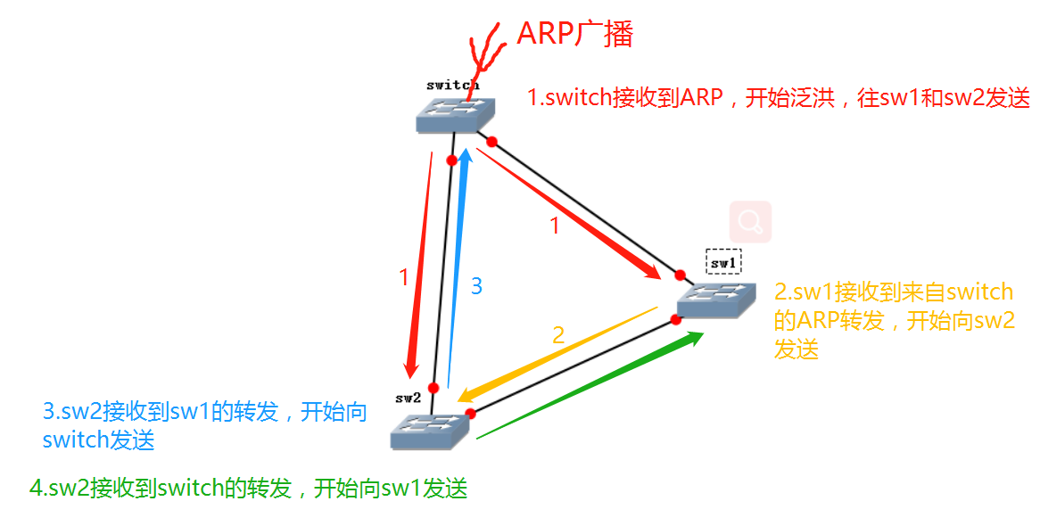
In the case where no VLAN, three switches interconnected to each other, the host switch received ARP broadcast start flooding sw1 and SW2 to send; forwarded from the switch sw1 is received, starts sending SW2; SW2 receive the switch and sw1 forwarding, they were sent to sw1 and switch; ------- thus the cycle, pass the buck down, causing congestion and link, on the formation of ARP broadcast storm. ARP broadcast will lead to a smooth transfer of useful data packets, normal communication can not; To solve this problem, split the logical broadcast domain VLAN adopted.
By creating a VLAN virtual interface, which is located in the port vlan, the corresponding PC port connectors which broadcast domains in
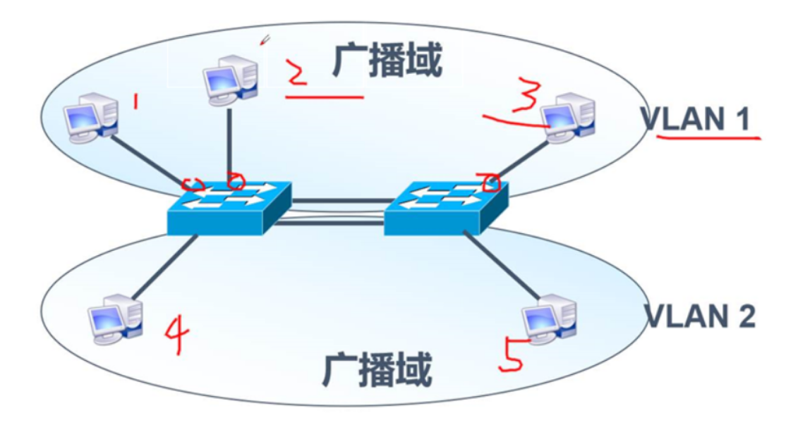
As shown, PC 123 can communicate with each terminal 45 can communicate with each other.
Analysis: VLAN can isolate broadcast
VLAN advantages:
You can control the radio,
Enhance network security,
Easy to simplify network management;
2.VLAN species
VLAN is divided into two categories, one is a static VLAN, one is dynamic VLAN.
Static VLAN is divided based on ports, is the dynamic MAC address-based VLAN

VLAN may comprise a plurality of ports, one port can only belong to one VLAN
3. Static VLAN configuration
Range 1) VLAN of
A total of 4096 VLAN, 0 and 4095 can only make use of the system; by default, all the ports of the switch belong to VLAN 1, the 1, the user can not be deleted
We are 1,2-1001,1025-4094 available, these VLAN
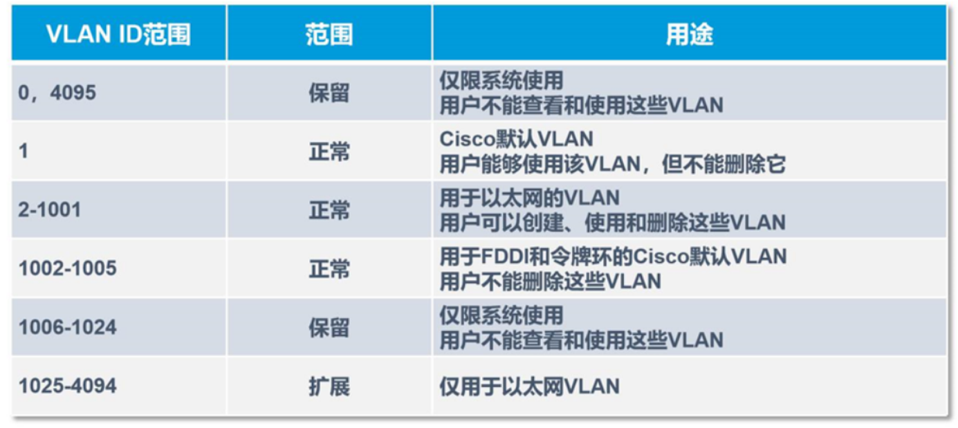
Operators will create a double VLAN, VLAN is in this range is 2-1001 1000 * 1000
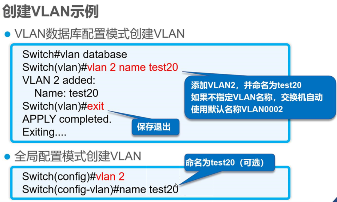
2) Create a VLAN
Static VLAN configuration roadmap steps of:
1. Create a VLAN
2. The respective ports of the switch is added to a VLAN
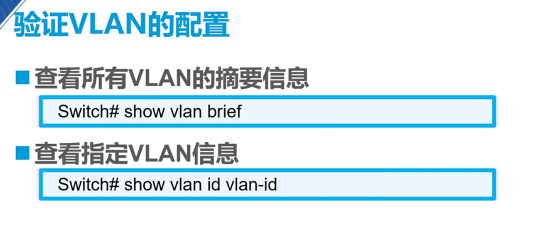
3. Verify VLAN configuration
The second of the most convenient
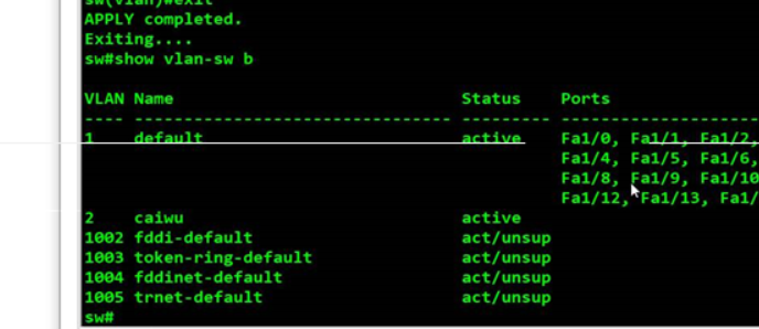
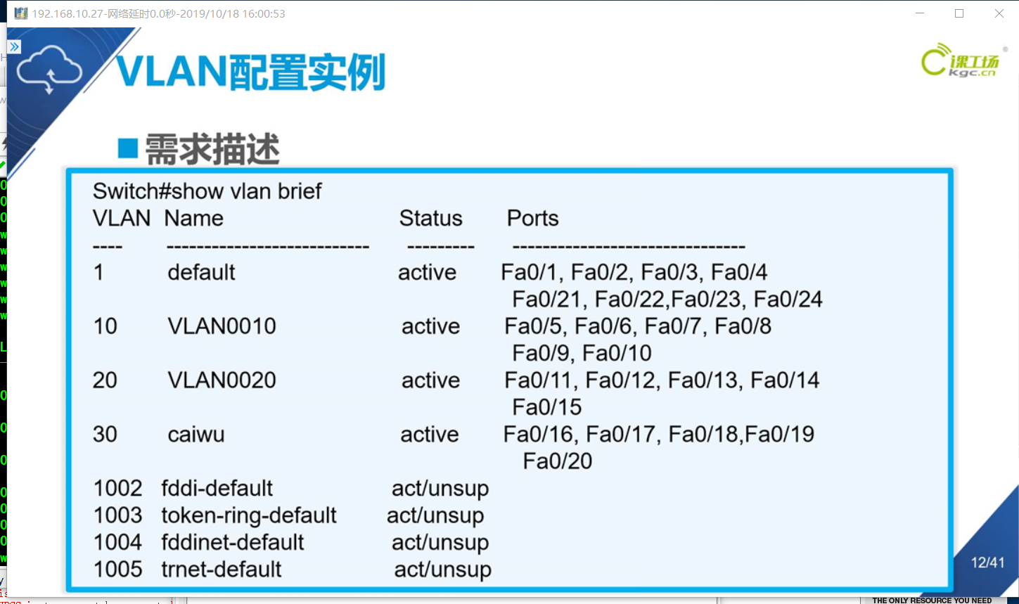
show vlan-switch brief command to view vlan information
Database Configuration:
Use abort exit VLAN database configuration mode
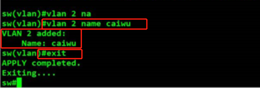
show vlan-switch brief command to view vlan information
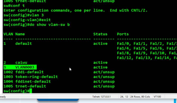
全局配置模式:创建VLAN 3,查看交换机VLAN 概要
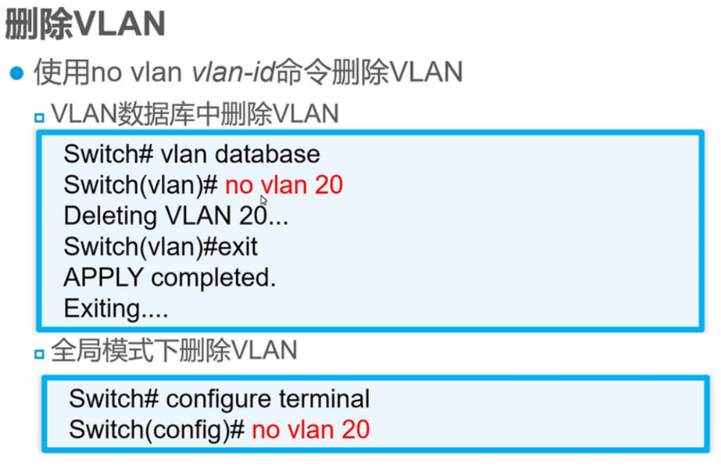
3)删除VLAN
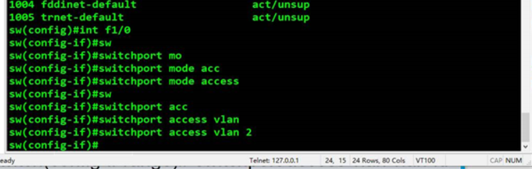
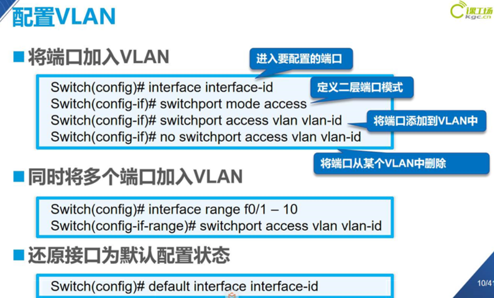
4)配置VLAN,将端口加入VLAN

模式有两种
1.接入链路模式 接入终端 例如PC access
2.中继链路模式 接入 其他网络设备(交换机,路由器等) trunk
区别:access链路上只能跑对应的VLAN数据
trunk可以跑所有VLAN数据
例如:
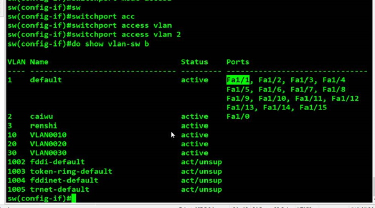
do show vlan-switch brief 查看路由VLAN表
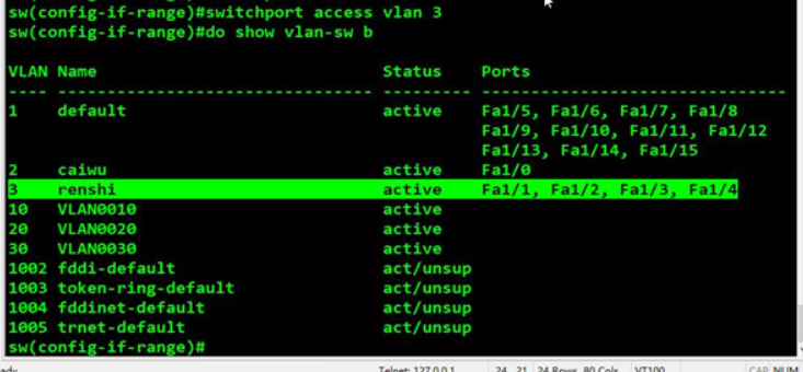
range 指配置连续的接口为一个VLAN,在这里把1/1-1/4的接口添加到VLAN3中,interface range fastethernet 1/1 -4,然后do show vlan-switch brief

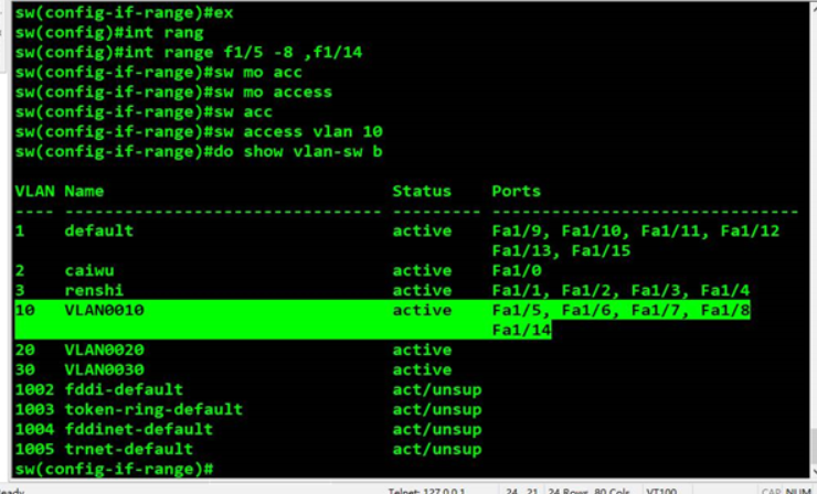
也可以连续端口加上单独的一个端口F1/14一起配置,用逗号隔开,interface range f1/5 -8,f1/14 ,switchport mode access ,定义二层端口模式为接入模式,switchport access vlan 10 ,将端口添加到VLAN10 中
interface f1/1,进入f1/1接口,no switchport access vlan 3,从VLAN3 中删除f1/1,do show vlan-switch brief,查看交换机VLAN信息概要,发现之前在VLAN3的f1/1回到了默认VLAN1中
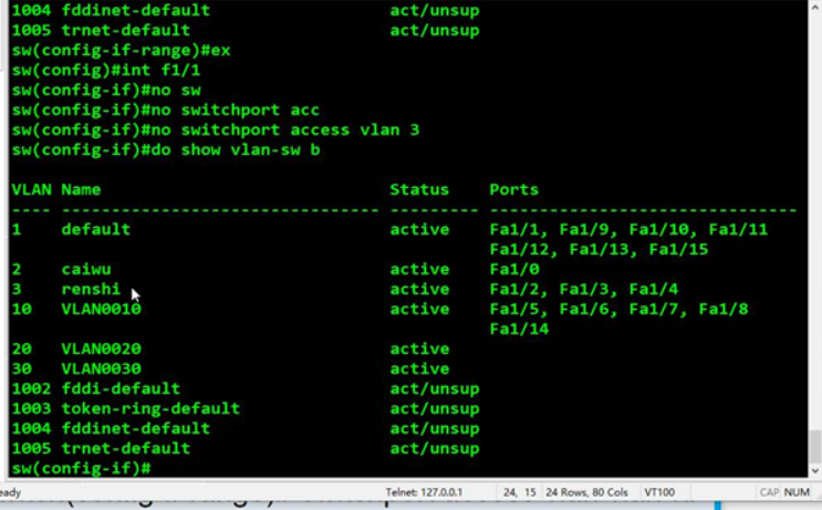
还原接口类似初始化端口,所有配置的信息都将会被清除
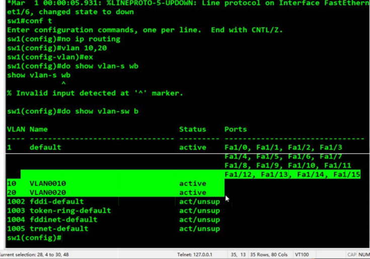
no ip routing,取消路由转发功能

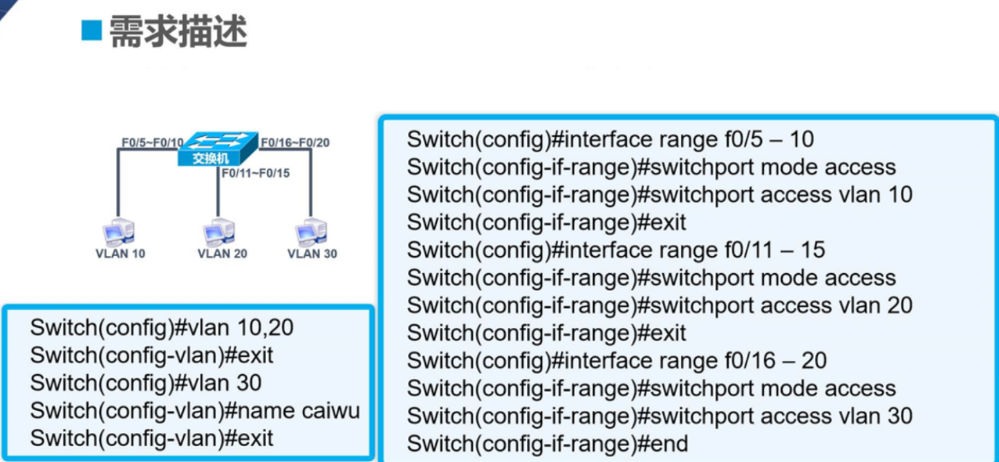
5)VLAN配置实例
4.Trunk介绍与配置
交换网络中链路类型一共有两种,分别是接入链路access,中继链路便是Trunk
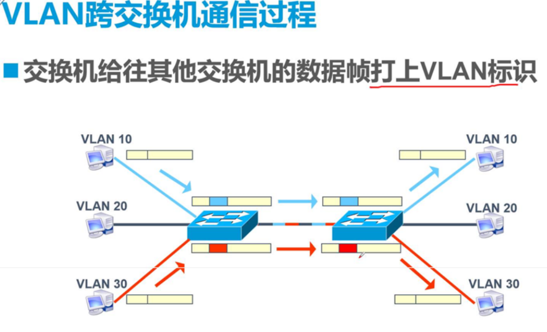
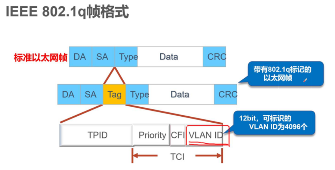
VLAN的标识
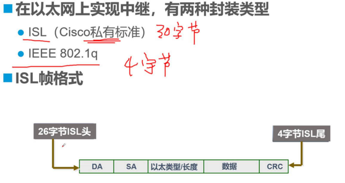
ISL占用30个字节
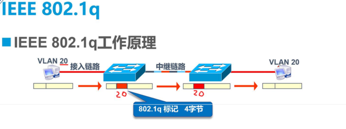
IEE占用4个字节
IEEE 802.1q 自身占用字节小,便于数据的优化传输,因此应用较广
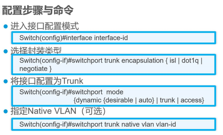
指定Native VLAN是类似一个VIP模式,只能有一个
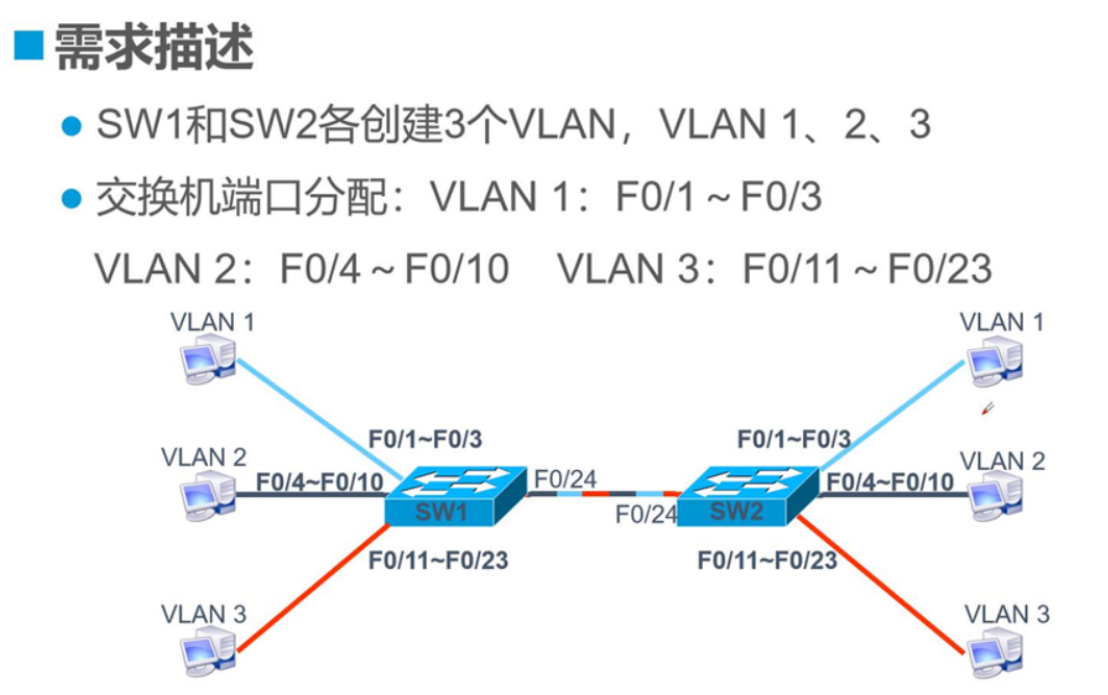
trunk配置实例
先配置主机IP地址

路由器进入全局模式configure terminal,取消路由功能no ip routing ,创建VLAN10和VLAN20

查看do show VLAN-switch brief检验
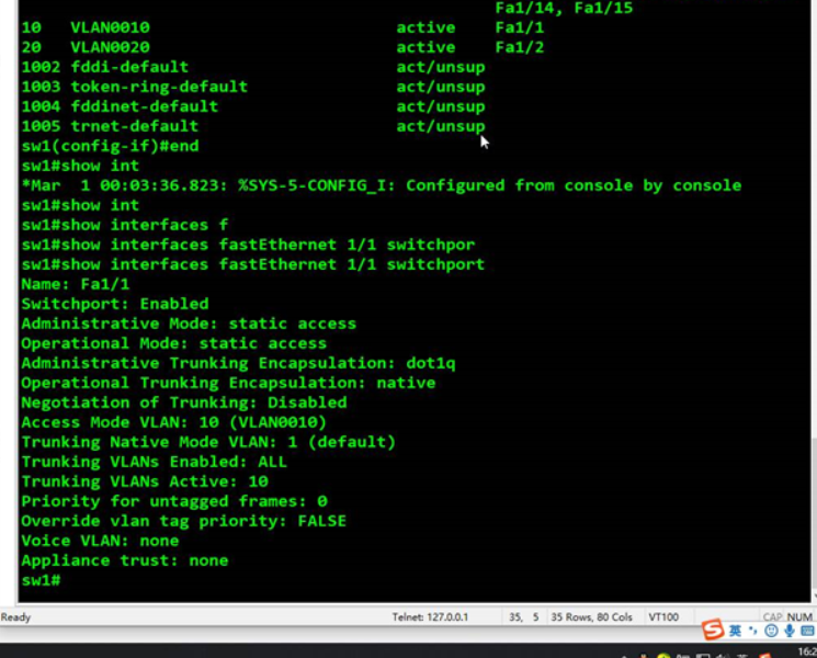
end退出,do show interface f1/1 switchport查看交换机接口f1/1的链路模式,为access
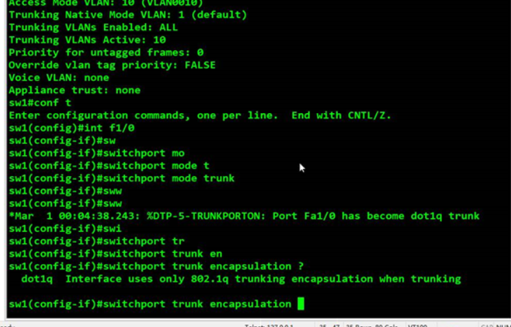
configure terminal进入全局模式,interface f1/0进入f1/0接口,switchport mode trunk接口模式
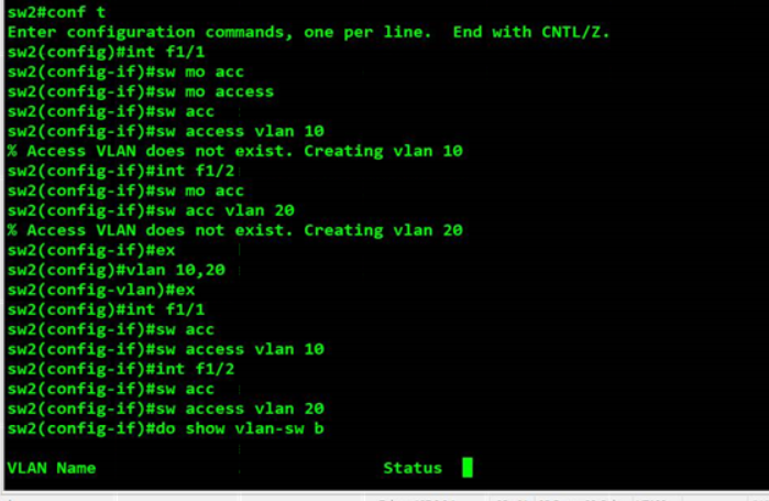
vlan10.20,创建VLAN10和VLAN20;interface f1/1,进入f1/1接口,switchport mode access vlan 10,配置交换机接口f1/1为VLAN 10;interface f1/2,进入f1/2接口;switchport access vlan 20 ,配置交换机接口f1/2为VLAN20;do show vlan-switch brief,查看交换机VLAN表检验是否配置完成
exit返回上一层;interface f1/0 进入f1/0接口;switchport mode trunk 配置f1/0接口模式为trunk模式;switchport trunk encapsulation dot1q,配置f1/0的接口trunk的封装类型为dot1q;do show vlan-switch brief,查看交换机路由表
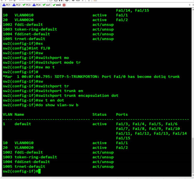
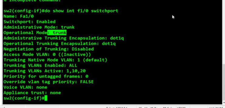
do show interface f1/0 switchport 查看f1/0接口链路模式


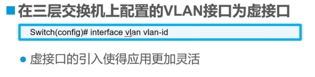
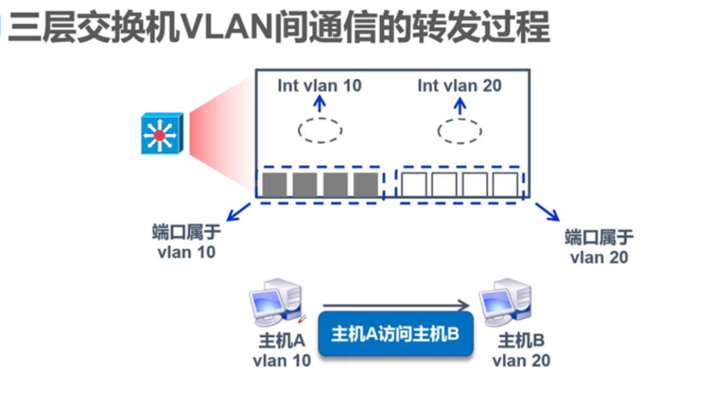
5.三层交换技术转发原理
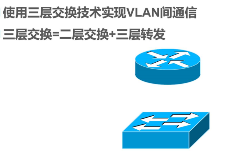
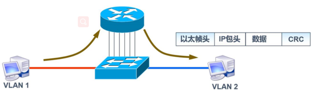
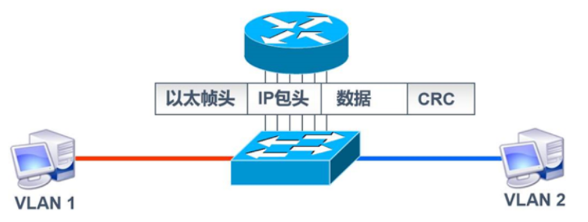
前身是单臂路由,把路由器上的一个物理接口划分成多个逻辑子接口做为VLAN的网关
在这个环境中,路由器负责数据包转发和转换VLAN标签,交换机负责穿标签和脱标签
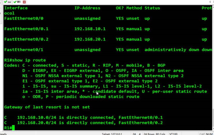
interface f0 / 0.1 enter logical subinterface f0 / 0.1; protocol interface is configured to a virtual sub-type of trunk DOT1Q; ip add 192.168.10.1 255.255.255.0 ip address configuration; no shut enabled; exit back to the previous; no shut enabled
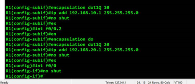
do show ip interface brief view corresponding to the interface ip; show ip route routing table
Proposed three-tier exchange address the deficiencies of single-arm routing to avoid congestion relay link
Three-tier exchange technology forward through the hardware level, so faster


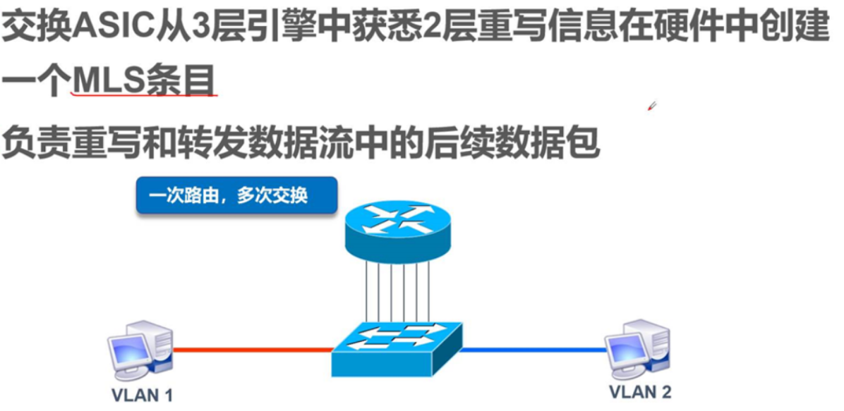
FIB written corresponding host and the corresponding vlan, adjacency table are linked write MAC, query MLS entry is checked two together, two tables together is MLS

6. The three switches disposed
The three switches interface into two VLAN, interface mode bit access
The three-port switch Trunk unified interface mode
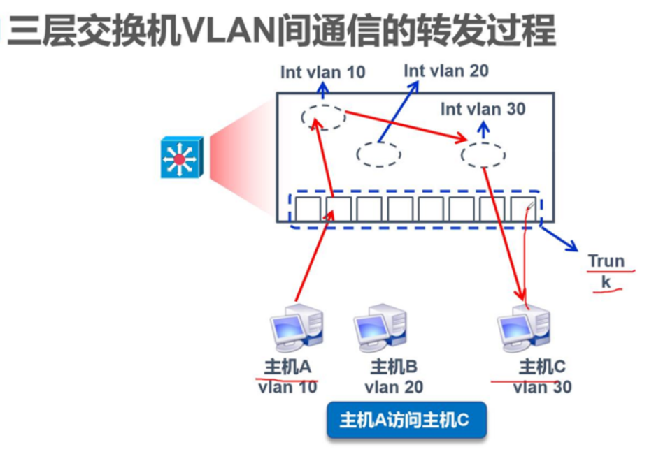
Trunk ports are the mode switches, jumpers, i.e., the interface is easy to switch
interface f0 / 0.1 enter logical subinterface f0 / 0.1; protocol interface is configured to a virtual sub-type of trunk DOT1Q; ip add 192.168.10.1 255.255.255.0 ip address configuration; no shut enabled; exit back to the previous; no shut enabled
do show ip interface brief view corresponding to the interface ip; show ip route routing table
Three switches configuration

Corresponding to the interface switch routing interface no switchport
