Network topology map construction
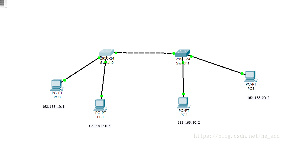
As shown in the figure, pc0 is connected to the f0/1 interface of switch0, pc1--switch0/2, pc2--switch1/1
pc3--switch1/2, and then the third switch is connected by a crossover cable. interface
Note: A straight cable is required between the host and the switch, and a crossover cable is required between the switches
Configure the host ip address
Click on the host with the mouse, and a box will pop up. You can see that the first one is the ip configuration, and you can configure it by clicking it. Configure the four hosts
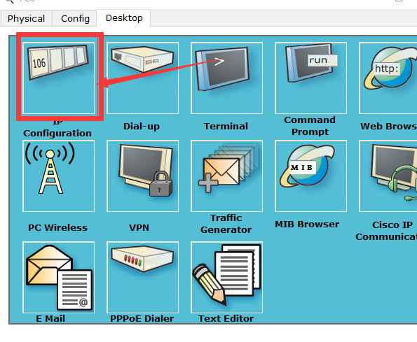

in turn .
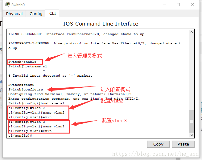
Configure the switch and divide the vlan
Click the switch to pop up this window, and then start dividing the vlan
to divide the port to the corresponding vlan 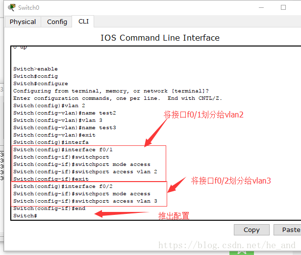
. Configure the trunk
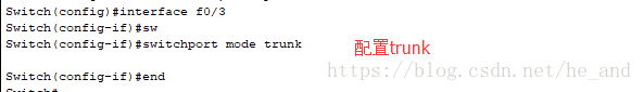
. Similarly, configure the trunk according to the corresponding steps on the second switch.
test
Now the configuration is basically over, try ping it:
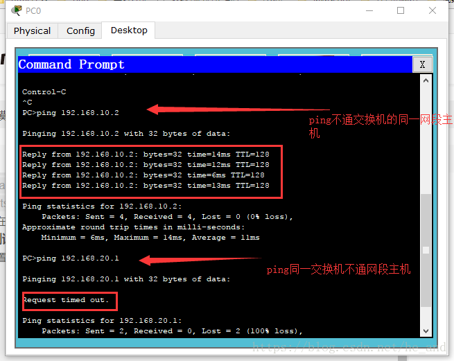
success!
Make small but daily progress