In the first method, the branch exit has NAT equipment, and the headquarters uses a template. The headquarters external line has a fixed address, and the branch exit does not need a fixed address.
If the branch has a fixed address and the headquarters has written the peer IP address negotiation, it is necessary to map UDP 500 and UDP 4500 to the corresponding port of the NAT server port corresponding to the ipsecvpn device in the egress NAT settings.

Main configuration:
All default policies are allowed. For details on how to enable the policy, you can wait and then use the command dis firewall session table ver to see
security-policy
default active permit.
i.配置接口IP地址。
system-view
[sysname] sysname FW_A
[FW_A] interface GigabitEthernet 1/0/1
[FW_A-GigabitEthernet1/0/1] ip address 10.1.1.1 24
[FW_A-GigabitEthernet1/0/1] quit
[FW_A] interface GigabitEthernet 1/0/2
[FW_A-GigabitEthernet1/0/2] ip address 1.1.2.1 24
[FW_A-GigabitEthernet1/0/2] quit
ii. Add the interface to the corresponding security zone.
[FW_A] firewall zone trust
[FW_A-zone-trust] add interface GigabitEthernet 1/0/1
[FW_A-zone-trust] quit
[FW_A] firewall zone untrust
[FW_A-zone-untrust] add interface GigabitEthernet 1/0/2
[FW_A-zone-untrust] quit
c. Configure the next hop address of the default route to 1.1.2.2 as the public network address
[FW_A] ip route-static 0.0.0.0 0 1.1.2.2
2. Configure IPSec on FW_A.
a. Define the protected data flow.
[FW_A] acl 3000
[FW_A-acl-adv-3000] rule 5 permit ip source 10.1.1.0 0.0.0.255 destination 10.1.2.0 0.0.0.255
b. Configure IPSec security proposal tran1. Use default parameters.
[FW_A] ipsec proposal tran1
[FW_A-ipsec-proposal-tran1] esp authentication-algorithm sha2-256 //
[FW_A-ipsec-proposal-tran1] esp encryption-algorithm aes-256 //The default is
[FW_A -ipsec-proposal-tran1] quit
c. Configure IKE security proposal. Use default parameters.
[FW_A] ike proposal 10
[FW_A-ike-proposal-10] authentication-method pre-share //The default is
[FW_A-ike-proposal-10] prf hmac-sha2-256 //The default is
[FW_A-ike -proposal-10] encryption-algorithm aes-256 //The default is
[FW_A-ike-proposal-10] dh group14 //The default is
[FW_A-ike-proposal-10] integrity-algorithm hmac-sha2-256 / /The default is
[FW_A-ike-proposal-10] quit
d.配置IKE Peer。
[FW_A] ike peer c
[FW_A-ike-peer-c] ike-proposal 10
[FW_A-ike-peer-c] pre-shared-key admin123
[FW_A-ike-peer-c] quit
e.配置IPSec策略模板temp。
[FW_A] ipsec policy-template temp 1
[FW_A-ipsec-policy-templet-temp-1] security acl 3000
[FW_A-ipsec-policy-templet-temp-1] proposal tran1
[FW_A-ipsec-policy-templet-temp-1] ike-peer c
[FW_A-ipsec-policy-templet-temp-1] quit
f. Create an IPSec policy and reference the IPSec policy template temp.
[FW_A] ipsec policy map1 10 isakmp template temp
g. Apply IPSec policy group map1 on interface GigabitEthernet 1/0/2.
[FW_A] interface GigabitEthernet 1/0/2
[FW_A-GigabitEthernet1/0/2] ipsec policy map1
[FW_A-GigabitEthernet1/0/2] quit
3. Configure the basic configuration of FW_C. a. Configure the interface IP address and add the interface to the domain.
Please configure the interface IP address according to the data in Figure 1.
Add interface GigabitEthernet 1/0/1 to the Trust zone
and add interface GigabitEthernet 1/0/2 to the Untrust zone.
For detailed steps, see the configuration of FW_A.
c. Configure static routing, the next hop address is 10.1.5.1 export routing address
ip route-static 0.0.0.0 0.0.0.0 10.1.5.1
4. Configure IPSec policy on FW_C. a. Define the protected data flow.
[FW_C] acl 3000
[FW_C-acl-adv-3000] rule 5 permit ip source 10.1.2.0 0.0.0.255 destination 10.1.1.0 0.0.0.255
b. Configure IPSec security proposal tran1. Use default parameters.
[FW_C] ipsec proposal tran1
[FW_C-ipsec-proposal-tran1] esp authentication-algorithm sha2-256 //The default is
[FW_C-ipsec-proposal-tran1] esp encryption-algorithm aes-256 //The default is
[FW_C -ipsec-proposal-tran1] quit
c. Configure IKE security proposal. Use default parameters.
[FW_C] ike proposal 10
[FW_C-ike-proposal-10] authentication-method pre-share //The default is
[FW_C-ike-proposal-10] prf hmac-sha2-256 //The default is
[FW_C-ike -proposal-10] encryption-algorithm aes-256 //The default is
[FW_C-ike-proposal-10] dh group14 //The default is
[FW_C-ike-proposal-10] integrity-algorithm hmac-sha2-256 / /The default is
[FW_C-ike-proposal-10] quit
d.配置IKE Peer。
[FW_C] ike peer a
[FW_C-ike-peer-a] ike-proposal 10
[FW_C-ike-peer-a] remote-address 1.1.2.1
[FW_C-ike-peer-a] pre-shared-key admin123
[FW_C-ike-peer-a] quit
e.Infrastructure IPSecPolicyMap1
[FW_C] ipsec policy map1 10 isakmp
[FW_C-ipsec-policy-isakmp-map1-10] security acl 3000
[FW_C-ipsec-policy-isakmp-map1-10] proposal tran1
[FW_C-ipsec - policy - isakmp - map1 - 10 ] ike - peer a
[ FW_C - ipsec - policy - isakmp - map1 - 10 ] quit
f. Apply IPSec policy group map1 on interface GigabitEthernet 1/0/2.
[FW_C] interface GigabitEthernet 1/0/2
[FW_C-GigabitEthernet1/0/2] ipsec policy map1
[FW_C-GigabitEthernet1/0/2] quit
c. Outbound router configuration.
acl number 2000
rule 5 permit source 10.1.2.0 0.0.0.255
interface GigabitEthernet0/0/0
ip address 10.1.5.1 255.255.255.0
interface GigabitEthernet0/0/1
ip address 1.1.5.1 255.255.255.0
nat outbound 2000
ip route-static 0.0.0.0 0.0.0.0 1.1.5.2
ip route-static 10.1.2.0 255.255.255.0 10.1.5.2
Result verification
1. After the configuration is completed, PC2 initiates access, and then PC1 and PC2 can access each other. PC2 can also access the public network.
2. PC2 can ping 1.1.2.1 of FW_A, and can view the NAT translation session entry on FW_B.
<FW_B> display firewall session table
Current Total Sessions : 2
udp VPN:public --> public 10.1.5.2:500[1.1.5.1:2048]–>1.1.2.1:500
udp VPN:public --> public 10.1.5.2 :4500[1.1.5.1:2048]–>1.1.2.1:4500
3. The corresponding IKE SA can be viewed on the headquarters firewall FW_A.
<FW_A> display ike sa
IKE SA information:
Conn-ID Peer VPN Flag(s) Phase RemoteType RemoteID
83887864    1.1.5.1:500           RD|A     v2:2   IP          1.1.5.1
83887652    1.1.5.1:500           RD|A     v2:1   IP          1.1.5.1
Number of IKE SA : 2
Flag Description:
RD–READY ST–STAYALIVE RL–REPLACED FD–FADING TO–TIMEOUT
HRT–HEARTBEAT LKG–LAST KNOWN GOOD SEQ NO. BCK–BACKED UP
M–ACTIVE S–STANDBY A–ALONE NEG–NEGOTIATING
4. FW_C on the branch can view the IKE SA whose peer is the headquarters. FW_C is the initiator and the flag is ST.
<FW_C> display ike sa
IKE SA information:
Conn-ID Peer VPN Flag(s) Phase RemoteType RemoteID
62887864    1.1.2.1:500           RD|ST|A  v2:2   IP          1.1.2.1
62887652    1.1.2.1:500           RD|ST|A  v2:1   IP          1.1.2.1
Number of IKE SA : 2
Flag Description:
RD–READY ST–STAYALIVE RL–REPLACED FD–FADING TO–TIMEOUT
HRT–HEARTBEAT LKG–LAST KNOWN GOOD SEQ NO. BCK–BACKED UP
M–ACTIVE S–STANDBY A–ALONE NEG–NEGOTIATING
5. A pair of bidirectional IPSec SAs can be viewed on the headquarters firewall FW_A, corresponding to the branch FW_C.
<FW_A> display ipsec sa brief
Current ipsec sa num:2
Spu board slot 1, cpu 1 ipsec sa information:
Number of SAs:2
Src address Dst address SPI VPN Protocol Algorithm
1.1.2.1         1.1.5.1       3923280450           ESP      E:AES-256 A:SHA2_256_128
1.1.5.1         1.1.2.1       2676437093           ESP      E:AES-256 A:SHA2_256_128
6. A pair of bidirectional IPSec SAs can be viewed on branch node FW_C. <FW_C> display ipsec sa brief
Current ipsec sa num:2
Spu board slot 1, cpu 1 ipsec sa information:
Number of SAs:4
Src address Dst address SPI VPN Protocol Algorithm
10.1.5.2         1.1.2.1       2179965693          ESP     E:AES-256 A:SHA2_256_128
1.1.2.1         10.1.5.2       3813759530          ESP     E:AES-256 A:SHA2_256_128
The second method is to use VPN and NAT, which means that the computer can communicate with the headquarters VPN and can access the external network, all on a firewall device.
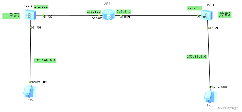
FW_A main configuration:
acl number 3000
rule 5 permit ip source 192.168.0.0 0.0.0.255 destination 172.16.0.0 0.0.0.255
ipsec proposal pro1
transfrom esp
ike proposal 10
ike peer fenbu_1
pre-shared-key admin
ike-proposal 10
nat traversal
ipsec policy-template temp1 1
security acl 3000
ike-peer fenbu_1
proposal pro1
ipsec policy policy1 1 isakmp template temp1
interface GigabitEthernet1/0/0
undo shutdown
ip address 1.1.1.1 255.255.255.0
service-manage ping permit
ipsec policy policy1
interface GigabitEthernet1/0/1
undo shutdown
ip address 192.168.0.1 255.255.255.0
service-manage ping permit
dhcp select interface
firewall zone trust
set priority 85
add interface GigabitEthernet0/0/0
add interface GigabitEthernet1/0/1
firewall zone untrust
set priority 5
add interface GigabitEthernet1/0/0
ip route-static 0.0.0.0 0.0.0.0 1.1.1.2
FW_B main configuration:
acl number 2000
rule 5 permit source 172.16.0.0 0.0.0.255
acl number 3000
rule 5 permit ip source 172.16.0.0 0.0.0.255 destination 192.168.0.0 0.0.0.255
ipsec proposal pro1
transfrom esp
ike proposal 10
ike peer zongbu
pre-shared-key admin
ike-proposal 10
remote-address 1.1.1.1
nat traversal
ipsec policy policy1 1 isakmp
security acl 3000
ike-peer zongbu
proposal pro1
interface GigabitEthernet1/0/0
undo shutdown
ip address 1.1.1.1 255.255.255.0
service-manage ping permit
ipsec policy policy1
interface GigabitEthernet1/0/1
undo shutdown
ip address 172.16.0.1 255.255.255.0
service-manage ping permit
dhcp select interface
firewall zone trust
set priority 85
add interface GigabitEthernet0/0/0
add interface GigabitEthernet1/0/1
ip route-static 0.0.0.0 0.0.0.0 2.2.2.1
nat-policy //First match the VPN data. If it is online, it will automatically go down and match the following policy
rule name policy_vpn
source-address 172.16.0.0 mask 255.255.255.0
destination-address 192.168.0.0 mask 255.255.255.0
action no -nat
rule name policy_internet
source-zone trust
destination-zone untrust
source-address 172.16.0.0 mask 255.255.255.0
action source-nat easy-ip
Notice:
If there is an internal server mapping port for the outbound department, then no-reverse must be added at the end of the command when mapping the nat server, so that the server-map table will not be generated, otherwise the VPN will not work.
nat server protocol tcp global 2.2.2.2 80 inside 172.16.0.100 80 no-reverse