
Author: PCIPG-Chenyi | Source: 3DCV
Add WeChat: dddvisiona, note: 3D point cloud, and join the group. Industry segmentation groups are attached at the end of the article.
1 What is 3D reconstruction
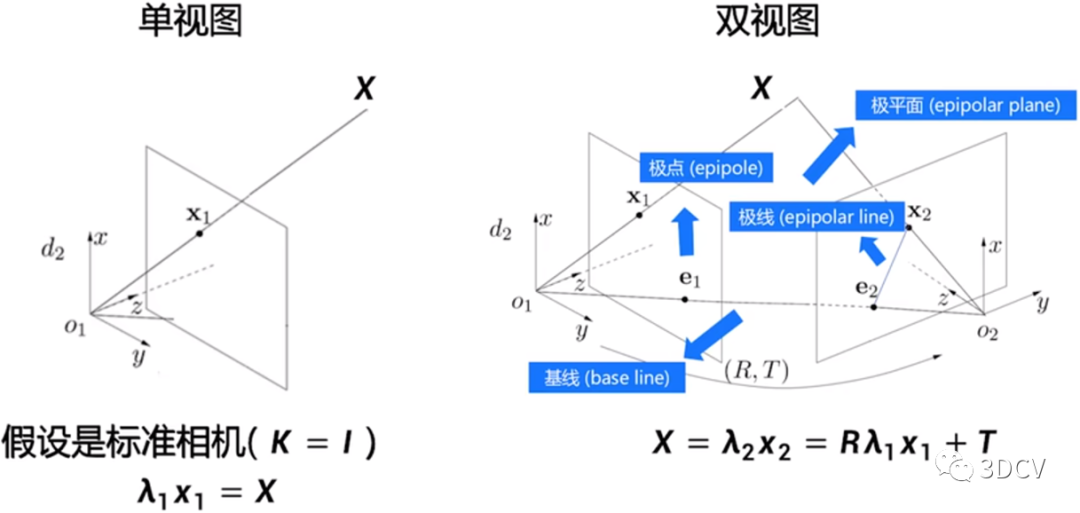
In computer vision, three-dimensional reconstruction refers to the process of reconstructing three-dimensional information based on single-view or multi-view images. Since the information in a single video is incomplete, 3D reconstruction requires the use of empirical knowledge. Multi-view 3D reconstruction (similar to human binocular positioning) is relatively easy. The method is to calibrate the camera first, that is, calculate the image coordinates of the camera. The relationship between the system and the world coordinate system, and then use the information in multiple two-dimensional images to reconstruct three-dimensional information. As shown in the figure below, 3D reconstruction can be simply understood as the process of camera touching the image.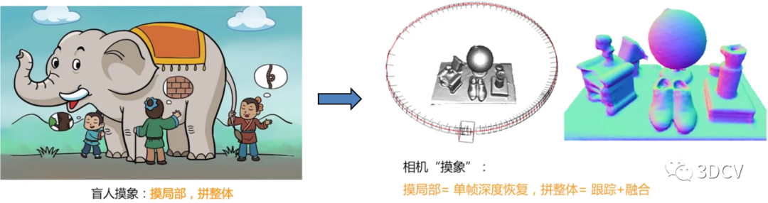
2 How to express the reconstruction results
1. Depth map (depth) Each pixel value represents the distance from the object to the camera xy plane, which is obtained by the depth camera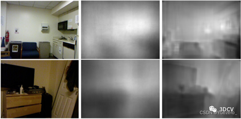 2. Point cloud (point cloud) Some A data set of points under the coordinate system, obtained by three-dimensional lidar
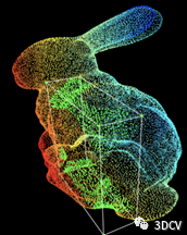 3. Mesh (mesh) A polygonal mesh composed entirely of triangles
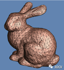 4. Volume A voxel is a sized point in three-dimensional space, a small square, which is equivalent to a pixel in three-dimensional space.
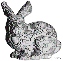
3 How to implement the entire reconstruction process
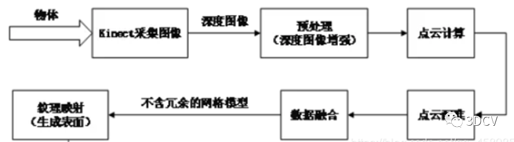
3.1 Acquisition of depth image
The depth image of the scene is captured by Kinect under the Windows platform, and its corresponding color image can be obtained at the same time. In order to obtain enough images, it is necessary to change different angles to shoot the same scene to ensure that all the information of the scene is included. The specific solution can be to fix the Kinect sensor to shoot objects on the rotating platform; or to rotate the Kinect sensor to shoot fixed objects.
It is recommended to study the 3D point cloud course of 3D Vision Workshop:
[1]3D point cloud processing: algorithm and practical summary
[2]Completely understand the point cloud processing tutorial based on Open3D!
3.2 Preprocessing
Due to limitations such as device resolution, its depth information also has many shortcomings. In order to better promote subsequent applications based on depth images, image enhancement processes such as denoising and repair must be performed on depth images. There are still many problems with the depth map output by the depth camera. For example, reflection on the surface of smooth objects, semi/transparent objects, dark objects, out of range, etc. will cause the depth map to be missing. Moreover, many depth cameras have large areas of missing depth values, which is a headache for algorithm engineers.
3.3 Calculate point cloud data
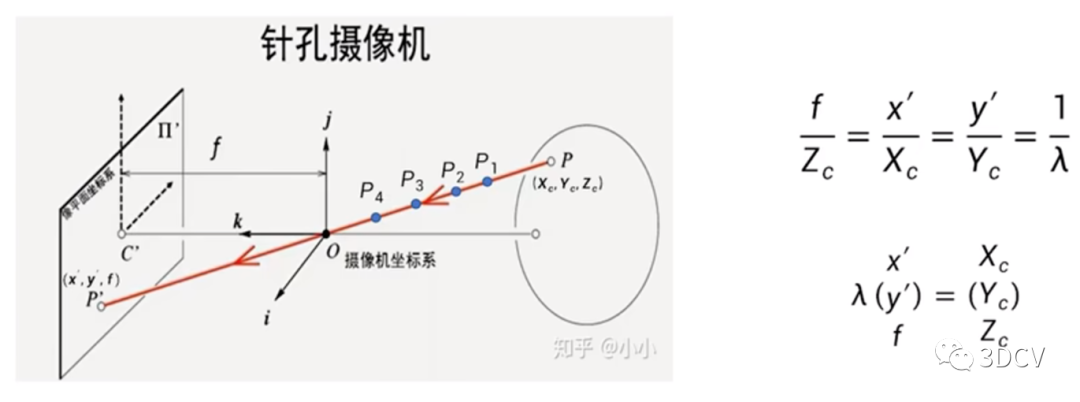
 The entire calculation process is actually a process from the world coordinate system to the pixel coordinate system (distortion is not considered). A picture is used to summarize the conversion relationship:
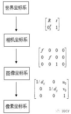
-
World coordinate system: describes the position of any object in the environment.
-
Camera coordinate system: The coordinate system established on the camera is defined to describe the position of the object from the perspective of the camera. It serves as an intermediate link between the world coordinate system and the image/pixel coordinate system. The unit is m. Taking the optical center of the camera as the coordinate origin, the X-axis and Y-axis are parallel to the X-axis and Y-axis of the image coordinate system respectively. The optical axis of the camera is the Z-axis, and its coordinate values are represented by (Xc, Yc, Zc).
-
Image coordinate system: describes the projection and transmission relationship of an object from the camera coordinate system to the image coordinate system, which facilitates further obtaining the coordinates in the pixel coordinate system. Taking the center of the image plane as the coordinate origin, the X-axis and Y-axis are parallel to the two vertical sides of the image plane respectively, and their coordinate values are represented by (x, y). The image coordinate system expresses the position of pixels in the image in physical units (such as millimeters).
-
Pixel coordinate system: describes the coordinates of the image point of the object on the digital image (photo). It is the coordinate system in which the information we actually read from the camera is located. The unit is units (number of pixels). Taking the upper left corner vertex of the image plane as the origin, the X-axis and Y-axis are parallel to the X-axis and Y-axis of the image coordinate system respectively, and their coordinate values are represented by (u, v). The images collected by digital cameras are first formed into the form of standard electrical signals, and then converted into digital images through analog-to-digital conversion. The storage form of each image is an M × N array. The value of each element in the image of M rows and N columns represents the grayscale of the image point. Each element like this is called a pixel, and the pixel coordinate system is the image coordinate system in pixels.
3.4 Point cloud registration
For multiple frames of scene images shot from different angles, there are certain common parts between each frame. In order to use depth images for three-dimensional reconstruction, the images need to be analyzed and the transformation parameters between each frame need to be solved. Depth image registration is based on the common part of the scene, superimposing and matching multiple frames of images acquired at different times, angles, and illumination into a unified coordinate system. Calculate the corresponding translation vector and rotation matrix while eliminating redundant information. In addition to restricting the speed of 3D reconstruction, point cloud registration will also affect the sophistication and global effect of the final model. Therefore, the performance of point cloud registration algorithms must be improved. The registration of three-dimensional depth information is divided into three categories according to different image input conditions and reconstruction output requirements: rough registration, fine registration and global registration. During the registration process, the matching error is evenly dispersed into multiple frames of images from each viewing angle, achieving the effect of reducing the cumulative error caused by multiple iterations. It is worth noting that although global registration can reduce errors, it consumes a large amount of memory storage space and greatly increases the time complexity of the algorithm.
3.5 Data fusion
The depth information after registration is still scattered and disordered point cloud data in space (as shown below), which can only show part of the information of the scene. Therefore, point cloud data must be fused to obtain a more refined reconstruction model. 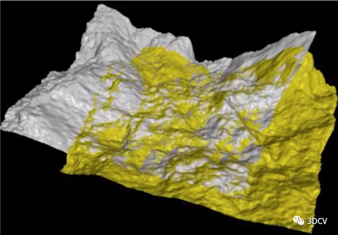 Construct a volume grid with the initial position of the Kinect sensor as the origin. The grid divides the point cloud space into a large number of small cubes, which are called voxels. In order to solve the problem of voxels occupying a large amount of space, the TSDF (Truncated Signed Distance Field) algorithm is proposed (as shown below). This method only stores several layers of voxels that are closer to the real surface, rather than all voxels. . Therefore, it can significantly reduce the memory consumption of KinectFusion and reduce model redundancy points.
  The surface is implicitly simulated by assigning TSDF (Truncated Signed Distance Field, truncated effective distance field) values to all voxels. As shown in the figure below, the TSDF value is calculated, which is the minimum distance value from this voxel to the reconstructed surface. When the TSDF value is greater than zero, it means that the voxel is in front of the surface; when TSDF is less than zero, it means that the voxel is behind the surface; when the TSDF value is closer to zero, it means that the voxel is closer to the real surface of the scene. A reconstructed surface is thus formed.
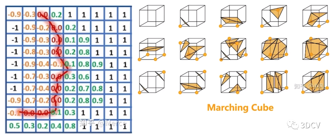
4 Classic algorithms for 3D reconstruction
4.1 Poisson algorithm
1. PrincipleA grid three-dimensional reconstruction algorithm based on octree and Poisson equation. Using indicator functions, gradient calculation can be realized for all effective indicator functions inside the space. The process of extracting isosurfaces by solving this function and obtaining the surface is the process of constructing Poisson's equation and solving it. 2. Algorithm process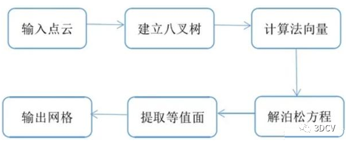 3. Core code
//----------------------------------法线估计------------------------------------
    pcl::NormalEstimation<pcl::PointXYZ, pcl::Normal> n;//法线估计对象
    pcl::PointCloud<pcl::Normal>::Ptr normals(new pcl::PointCloud<pcl::Normal>);//存储估计的法线
    pcl::search::KdTree<pcl::PointXYZ>::Ptr tree(new pcl::search::KdTree<pcl::PointXYZ>);
    tree->setInputCloud(cloud);
    n.setInputCloud(cloud);
    n.setSearchMethod(tree);
    n.setKSearch(10);
    n.compute(*normals);
    //-------------------------------连接法线和坐标---------------------------------
    pcl::PointCloud<pcl::PointNormal>::Ptr cloud_with_normals(new pcl::PointCloud<pcl::PointNormal>);
    pcl::concatenateFields(*cloud, *normals, *cloud_with_normals);
    //---------------------------------泊松重建-------------------------------------
    pcl::search::KdTree<pcl::PointNormal>::Ptr tree2(new pcl::search::KdTree<pcl::PointNormal>);
    tree2->setInputCloud(cloud_with_normals);
    pcl::Poisson<pcl::PointNormal> pn;
    pn.setSearchMethod(tree2);
    pn.setInputCloud(cloud_with_normals);
    pn.setDepth(6);              // 设置将用于表面重建的树的最大深度
    pn.setMinDepth(2);
    pn.setScale(1.25);           // 设置用于重建的立方体的直径与样本的边界立方体直径的比值
    pn.setSolverDivide(3);       // 设置块高斯-塞德尔求解器用于求解拉普拉斯方程的深度。精度
    pn.setIsoDivide(6);          // 设置块等表面提取器用于提取等表面的深度 平滑度
    pn.setSamplesPerNode(10);    // 设置每个八叉树节点上最少采样点数目 八叉树节点上的采样点数速度
    pn.setConfidence(false);     // 设置置信标志,为true时,使用法线向量长度作为置信度信息,false则需要对法线进行归一化处理
    pn.setManifold(false);       // 设置流行标志,如果设置为true,则对多边形进行细分三角话时添加重心,设置false则不添加
    pn.setOutputPolygons(false); // 设置是否输出为多边形(而不是三角化行进立方体的结果)。
4. Result display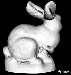
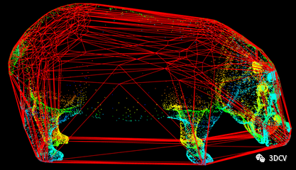
4.2 Convex Hull Algorithm
1. Algorithm flowGiven n vertices in a three-dimensional space, solve the convex hull surface composed of these n vertices 1) First, select a tetrahedron (initial convex hull) formed by 4 points, and then add a new point P each time. There are two situations: a. If P is within the convex hull, it can be skipped. b. P is outside the convex hull. For a certain edge, find the surface S containing the edge that can be "visible" from this point (whether visible can be calculated using the normal vector to see if the point is outside the surface), delete these surfaces S, Then use the other two sides of S except this side and point P to form two new surfaces. By traversing all the edges in this way, P is added to the convex hull and a new convex hull is formed. 2) Traverse all points and finally obtain the convex hull of the entire point set. 2. Core code
//---------------------对上述点云构造凸包-----------------------
 pcl::ConvexHull<pcl::PointXYZ> hull;  //创建凸包对象
 hull.setInputCloud(cloud);            //设置输入点云
 hull.setDimension(3);                 //设置输入数据的维度(2D或3D)
 vector<pcl::Vertices> polygons;       //设置pcl:Vertices类型的向量,用于保存凸包顶点

 pcl::PointCloud<pcl::PointXYZ>::Ptr surface_hull(new pcl::PointCloud<pcl::PointXYZ>);//该点云用于描述凸包形状

 hull.setComputeAreaVolume(true);       //设置为真,则调用qhr库来计算凸包的总面积和体积
 hull.reconstruct(*surface_hull, polygons);//计算3D凸包结果
 float Area = hull.getTotalArea();      //获取凸包的总面积
 float Volume = hull.getTotalVolume();  //获取凸包的总体积
 cout << " 凸包的面积为: " << Area << endl;
 cout << " 凸包的体积为: " << Volume << endl;
3. Result display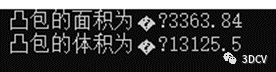
4.3 Concave envelope algorithm
1. PrincipleOn a three-dimensional level, we can imagine this algorithm as a ball rolling among a bunch of points. Three points that meet the conditions will form a polygon. , this condition is an "empty ball rule" (similar to the empty circle rule), which means that this ball will not contain other points except three basic points. 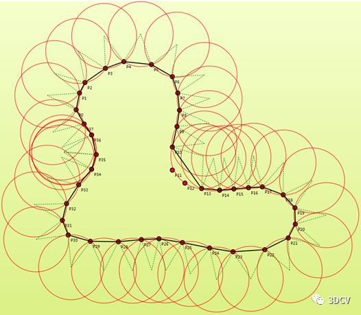
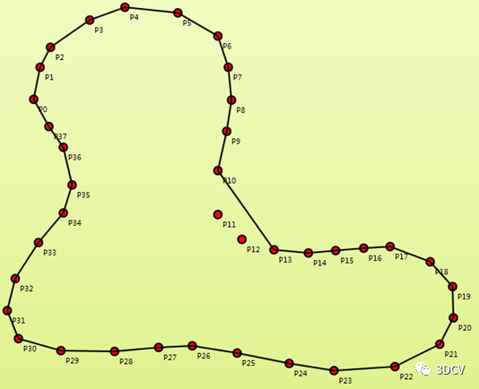 As can be seen from the picture on the right, the ball has not rolled to the two points P11 and P12, so at this time we guess: if we reduce the radius of the ball, can we traverse more points? So the output point cloud will be clearer and more complete? 2. Core code
pcl::ConcaveHull<pcl::PointXYZ> cavehull;
 cavehull.setInputCloud(cloud);
 cavehull.setAlpha(0.001);
 vector<pcl::Vertices> polygons;
 cavehull.reconstruct(*surface_hull, polygons);// 重建面要素到点云
3. Result displayWhen setting the radius to 0.5, 0.1, 0.05, and 0.02 respectively, the following four results are obtained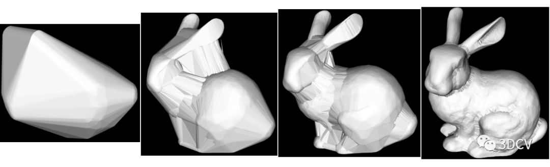 Therefore, the previous conjecture is correct.
In addition to these three reconstruction algorithms, there are also greedy, Delaunay triangulation algorithms and so on. We will explain this part later in"3D Vision from Beginner to Mastery" Knowledge Planet.
5 References
https://mp.weixin.qq.com/s/LGnOqDVefzIF_yRZO2ZB7w
https://www.bilibili.com/video/BV1zY4y1X7UJ
—END—
Efficiently learn 3D vision trilogy
The first step is to join the industry exchange group and maintain the advancement of technology.
Currently, the workshop has established multiple communities in the 3D vision direction, including SLAM, industrial 3D vision, and autonomous driving. The subdivisions include: [Industrial directionAutonomous driving direction]Multi-sensor fusion, ORB-SLAM, laser SLAM, robot navigation, RTK|GPS|UWB and other sensor exchange groups, SLAM comprehensive discussion group; [SLAM direction]3D point cloud, structured light, robotic arm, defect detection, 3D measurement, TOF, camera calibration, comprehensive group; [Three-dimensional reconstruction direction]NeRF, colmap, OpenMVS, etc. In addition to these, there are also communication groups for job hunting, hardware selection, and visual product implementation. You can add the assistant on WeChat: dddvisiona, note: add group + direction + school | company, the assistant will add you to the group.

Step 2: Join Knowledge Planet and get answers to your questions in a timely manner
Video courses for the field of 3D vision (3D reconstruction, 3D point cloud, structured light, hand-eye calibration, camera calibration, laser/visual SLAM, autonomous driving, etc.), source code sharing, knowledge point summary, introductory and advanced learning Routes, latest paper sharing, questions and answers etc. are deeply cultivated, and algorithm engineering personnel from various major manufacturers provide technical guidance. At the same time, Planet will work with well-known companies to publish 3D vision-related algorithm development positions and project docking information, creating a gathering area for die-hard fans integrating technology, employment, and project docking. 6,000+ Planet members will work together to create a better AI world. Progress, Knowledge Planet Entrance:"3D Vision from Beginner to Master"
Learn 3D vision core technology, scan and view, and get an unconditional refund within 3 days
The third step is to systematically learn 3D vision, deeply understand and run the module knowledge system
If you want to study systematically in a certain subdivision of 3D vision [from theory, code to practice], we recommend the 3D vision quality course learning website: www.3dcver.com
Scientific research paper writing:
Foundation Course:
[2]Linux embedded system tutorial for three-dimensional vision [theory + code + practical]
[3]How to learn camera model and calibration? (Code + Practical Combat)
[4]ROS2 from entry to mastery: theory and practice
[5]Comprehensive understanding of dToF radar system design [theory + code + practical]
Industrial 3D Vision Direction Course:
[3]Robotic arm grabbing from entry to practical course (theory + source code)
[4]3D point cloud processing: algorithm and practical summary
[5]Completely understand the point cloud processing tutorial based on Open3D!
[6]3D visual defect detection tutorial: theory and practice!
SLAM direction course:
[3]Completely understand visual-inertial SLAM: VINS-Fusion principle and source code analysis
[5](Second issue) ORB-SLAM3 theoretical explanation and code analysis
Visual 3D reconstruction
Autonomous driving course:
[3]Monocular depth estimation method: algorithm review and code implementation
[5]How to deploy deep learning models into actual projects? (Classification + Detection + Segmentation)
at last
1, Recruitment of authors for 3D visual article submissions
3, Top conference paper sharing and 3D vision sensor industry live broadcast invitation