It’s been a while since I’ve written a blog. I’ve been working on my graduation thesis recently and I’ve coded a lot of words, but I haven’t touched a blog in a while. When finishing the design, I tried to solve some problems that I had not completed for a long time, and also made some effects to play with. This time I will remember this thing, so that I can use it at any time if needed in the future. Therefore, this blog will not delve into how something is deduced from front to back (it usually takes half a week to write that way, and it took me a month to spin that blog before). This article mainly writes about myself. Some ideas and pitfalls when working on projects.
Today's blog will record the post-processing stroke method. Speaking of strokes is relatively simple. In the miscellaneous article, I recorded the method of constructing strokes based on the model itself. Although it is very watery, and for the model The requirements for normal lines are high. In my graduation design, I used modeling done by MagicalVoxel (because I am too lazy and don’t want to use 3Dmax, so I just want to be lazy). The effects of this modeling software are pretty good, and it’s very simple. I do it while listening to cross talk, and it’s super comfortable.
Thoughts when making strokes:
But the consequence of this is that if I need to do some strokes, it is super difficult. For example, a pot I made with MagicalVoxel looks like this:

This effect works well in MagicalVoxel, but there will be many problems when placed in Unity. Not to mention that the texture file of the Vox file exported by MagicalVoxel is saved as vertex color, which is different from the texture of the general model, so when sampling Color problems may occur. Moreover, MagicalVoxel must define the center of the model by itself after exporting it, so each model must be adjusted by itself and represented by an empty object. The most annoying thing is that if you stroke this type of model, the effect of directly using the vertices of the model will be very poor. For example, for the pot above, use the stroke after normal line extension and then use the template to test The effect after subtraction is (my stroke here is green):

If you use offset instead to stroke the solid color model, the effect will be similar to the above, but even worse.
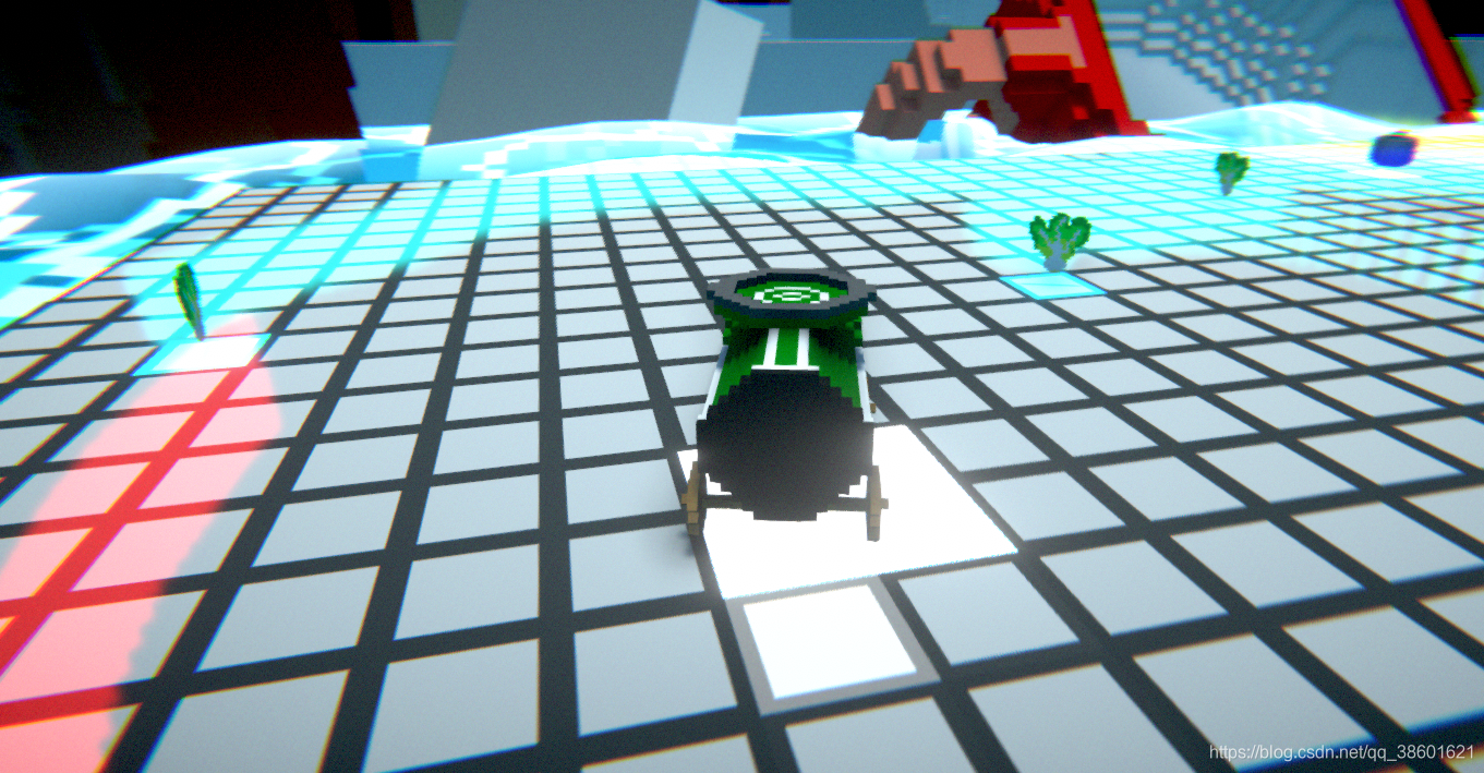
Therefore, for a model with a single normal direction like MagicalVoxel, it is impossible to perform stroke coloring on a single model. Generally, post-processing is used for strokes. Post-processing stroke convolution I wrote about a stroke effect at the end of the blur article. For the effect in the scene, the color of a model is judged based on the convolution kernel and then the stroke is defined. I won’t repeat it here. For projects using MagicalVoxel modeling, if the following model exists in the scene:

If we use an ordinary color stroke convolution kernel to create the stroke effect of the picture, then the effect for the above picture will be like this:

Now it seems that this is still usable, it can only be said that it is slightly inconsistent with the effect I want. However, because it is based on color, in many cases it may cause a messy and messy effect on the screen.
Stroke using depth and normal textures
For my project, when I was trying to stroke, I once thought about making a stroke similar to MagicalVoxel. In MagicalVoxel, if the Grid stroke in the lower left corner is turned on, it looks like this:

When I use MagicalVoxel, I feel that this effect is quite cool for the block model, because it looks more layered every time. I fiddled with it for a few days and found that the stroke here can be sampled and overlaid using the screen normal texture and the screen depth texture to simulate this effect. Specifically in Unity it looks like this:

This effect looks okay, and it is very simple. You only need a few codes to achieve this effect. You only need to combine the stroke results of the depth map and the stroke results of the normal map.
Shader code:
Shader "Custom/LineNormal"
{
    Properties
    {
        _MainTex("Texture",2D)="white"{}
        _EdgeColor("EdgeColor",Color)=(1,1,1,1)
        _NoneEdgeColor("NoneEdgeColor",Color)=(1,1,1,1)
        _SampleRange("SampleRange",float)=1.0
        _NormalDiffThreshold("NormalDiffThreshold",float)=1.0
    }

    CGINCLUDE
    #include "UnityCG.cginc"

    struct VertexData
    {
        float4 vertex:POSITION;
        float2 uv:TEXCOORD0;
    };

    struct VertexToFragment
    {
        float4 pos:SV_POSITION;
        float2 uv[9]:TEXCOORD0;
    };

    sampler2D _MainTex;
    float4 _MainTex_TexelSize;

    sampler2D _CameraDepthNormalsTexture;
    sampler2D _CameraDepthTexture;
    float4 _NoneEdgeColor;
    float4 _EdgeColor;
    float _SampleRange;
    float _NormalDiffThreshold;

    VertexToFragment myVertex(VertexData v)
    {
        VertexToFragment VToF;
        VToF.pos=UnityObjectToClipPos(v.vertex);
        VToF.uv[0]=v.uv+float2(-1,1)*_MainTex_TexelSize*_SampleRange;
        VToF.uv[1]=v.uv+float2(0,1)*_MainTex_TexelSize*_SampleRange;
        VToF.uv[2]=v.uv+float2(1,1)*_MainTex_TexelSize*_SampleRange;
        VToF.uv[3]=v.uv+float2(-1,0)*_MainTex_TexelSize*_SampleRange;
        VToF.uv[4]=v.uv;
        VToF.uv[5]=v.uv+float2(1,0)*_MainTex_TexelSize*_SampleRange;
        VToF.uv[6]=v.uv+float2(-1,-1)*_MainTex_TexelSize*_SampleRange;
        VToF.uv[7]=v.uv+float2(0,-1)*_MainTex_TexelSize*_SampleRange;
        VToF.uv[8]=v.uv+float2(1,-1)*_MainTex_TexelSize*_SampleRange;
        return VToF;
    }

    float CheckEdge(fixed4 a,fixed4 b)
    {
        float2 normalDiff=abs(a.xy-b.xy);
        return (normalDiff.x+normalDiff.y)<_NormalDiffThreshold;
    }

    fixed4 myFragmentDepth(VertexToFragment VToF):SV_TARGET
    {
        fixed4 getColor=tex2D(_MainTex,VToF.uv[4]);
        fixed4 edge1=tex2D(_CameraDepthTexture,VToF.uv[0]);
        fixed4 edge2=tex2D(_CameraDepthTexture,VToF.uv[1]);
        fixed4 edge3=tex2D(_CameraDepthTexture,VToF.uv[2]);
        fixed4 edge4=tex2D(_CameraDepthTexture,VToF.uv[3]);
        fixed4 edge5=tex2D(_CameraDepthTexture,VToF.uv[5]);
        fixed4 edge6=tex2D(_CameraDepthTexture,VToF.uv[6]);
        fixed4 edge7=tex2D(_CameraDepthTexture,VToF.uv[7]);
        fixed4 edge8=tex2D(_CameraDepthTexture,VToF.uv[8]);

        float result=1.0;
        result*=CheckEdge(edge1,edge8);
        result*=CheckEdge(edge2,edge7);
        result*=CheckEdge(edge3,edge6);
        result*=CheckEdge(edge4,edge5);
        return lerp(_EdgeColor,getColor,result);

    }

    fixed4 myFragment(VertexToFragment VToF):SV_TARGET
    {
        fixed4 getColor=tex2D(_MainTex,VToF.uv[4]);
        fixed4 edge1=tex2D(_CameraDepthNormalsTexture,VToF.uv[0]);
        fixed4 edge2=tex2D(_CameraDepthNormalsTexture,VToF.uv[1]);
        fixed4 edge3=tex2D(_CameraDepthNormalsTexture,VToF.uv[2]);
        fixed4 edge4=tex2D(_CameraDepthNormalsTexture,VToF.uv[3]);
        fixed4 edge5=tex2D(_CameraDepthNormalsTexture,VToF.uv[5]);
        fixed4 edge6=tex2D(_CameraDepthNormalsTexture,VToF.uv[6]);
        fixed4 edge7=tex2D(_CameraDepthNormalsTexture,VToF.uv[7]);
        fixed4 edge8=tex2D(_CameraDepthNormalsTexture,VToF.uv[8]);
        float result=1.0;
        result*=CheckEdge(edge1,edge8);
        result*=CheckEdge(edge2,edge7);
        result*=CheckEdge(edge3,edge6);
        result*=CheckEdge(edge4,edge5);
        return lerp(_EdgeColor,getColor,result);
    }
    ENDCG

    SubShader
    {
        pass
        {
            CGPROGRAM
            #pragma vertex myVertex
            #pragma fragment myFragment
            ENDCG
        }
        pass
        {
            CGPROGRAM
            #pragma vertex myVertex
            #pragma fragment myFragmentDepth
            ENDCG
        }
    }
}
In the post-processing script, you only need to add the two Passes:
        Material.SetFloat("_edgeOnly", EdgeOnly);
        Material.SetColor("_EdgeColor", EdgeColor);
        Material.SetColor("_NoneEdgeColor", NoneEdgeColor);
        Material.SetFloat("_SampleRange", SampleRange);
        Material.SetFloat("_NormalDiffThreshold", NormalDiffThreshold);
        RenderTexture RT1 = RenderTexture.GetTemporary(src.width, src.height, 0);
        Graphics.Blit(src, RT1, Material, 0);
        Graphics.Blit(RT1, dst, Material, 1);
        RenderTexture.ReleaseTemporary(RT1);
Finally, you can output the effect:

This effect is enough, but the thesis supervisor said that the picture looks too dirty, and then said it was ugly. I thought I had no choice but to rethink the stroke method.
Stroking using the command buffer
In my project, post-processing has the following requirements:
- In terms of effects: Different objects are randomly generated in the scene at any time, and strokes are rendered in every frame starting from the first moment they are generated. Different objects have different stroke colors, and they are rendered on the screen at the same time. Full control over stroke effects.
- Efficiency: Since the number of objects is completely unpredictable, the performance consumed by each stroke effect cannot be too much, because there are many randomly generated items in the scene. Therefore, you cannot improve the stroke by raising the camera.
According to this requirement, none of the above stroke effects can be used, because they are all strokes based on the screen texture. On the screen texture, I couldn't distinguish each object at all and then stroke based on the object. So the method I came up with was to render a solid color map for each object in the scene, then post-process the map and paste it on the screen. It’s nothing more than the following steps:
- Get the color of each object and use a solid color Shader to render the object's renderer. Output a map.
- Apply operations to this map, including Gaussian blur or expanding the color range.
- Subtract the original image from the expanded texture to obtain the outline.
- Glue the outline to the screen.
I was a little at a loss when I thought of this, because if I want to render a separate texture for an object, the first thing I think of is to set up a separate camera for rendering for an object, but the consequence of this is that the objects in my scene The more, the more cameras are needed, and if the rendering target of a camera is distinguished based on layer, each camera needs an independent level, and each object needs an independent level. And in order to adapt these cameras to the main camera, their Transform parameters should be synchronized. . . . This seems very cumbersome and thankless, so I stopped here when I first thought about it, because it would be better not to do it, and the final performance will continue to increase, and the effect may be very poor. After that I never thought about doing tracing again.
Afterwards, I read some articles about command buffering on the Internet, which gave me ideas about strokes. The command buffer can specify a renderer to use a material to render, and output the rendered image to a RenderTexture, which is undoubtedly good. Each command buffer has a one-to-one correspondence with a RenderTexture, and they can be easily described using a dictionary. In my project, when an object is generated:
    public void Add(ICon getICon)
    {
        CommandBuffer newBuffer = new CommandBuffer();
        RenderTexture newTexture = RenderTexture.GetTemporary(Screen.width, Screen.height, 0);
        newBuffer.SetRenderTarget(newTexture);
        newBuffer.ClearRenderTarget(true, true, Color.black);
        Material newMaterial = new Material(ColorShader);
        Color materialColor;
        TestIConPool.ColorDictionary.TryGetValue(getICon.returnNumOfDic(), out materialColor);
        newMaterial.SetColor("_OutLineColor", materialColor * 10f);
        newBuffer.DrawRenderer(getICon.myRenderer, newMaterial);
        BufferDic.Add(newBuffer, newTexture);
        IConBufferDic.Add(getICon, newBuffer);
    }
Among them, TestIConPool refers to the object color pool, and the object will take out the corresponding color from the pool according to the type index; ColorShader is just a very simple Shader that outputs a solid color model; BufferDic is a dictionary that stores buffering and rendering textures, type Is <CommandBuffer, RenderTexture>. At the same time, ICon (the abstract subclass of the item in the project) and the buffer are saved together to form a dictionary. The type of the dictionary is <ICon, CommandBuffer>. The reason for saving this dictionary is that when the scene destroys this item, the corresponding Buffer and texture also need to be cleared:
    public static void Remove(ICon removeICon)
    {
        CommandBuffer removebuffer;
        IConBufferDic.TryGetValue(removeICon, out removebuffer);
        IConBufferDic.Remove(removeICon);
        RenderTexture getRT;
        BufferDic.TryGetValue(removebuffer, out getRT);
        BufferDic.Remove(removebuffer);
        removebuffer.Release();
        removebuffer = null;
        RenderTexture.ReleaseTemporary(getRT);
        getRT = null;
    }
In my project, there are many situations where an item is cleared, but it would be troublesome if each situation depends on the instance of this script, so Remove is a static method so that it can be called by other scripts.
soft stroke
Generally, there are two types of strokes, one is hard strokes, and the second is soft strokes (in some games, the strokes are hard first and then gradually become softer). These two strokes are nothing more than slightly modified during sampling. Soft stroke is very simple, just need Gaussian Blur + Texture Overlay Pass + Texture Subtraction Pass. Shader is very simple:
Shader "Custom/OutLineShader"
{
    Properties
    {
        _MainTex ("Texture", 2D) = "white" {}
        _OutLineSize("OutLineSize",int)=4
        _OutLineTexture("OutLineTexture",2D)="white"{}
        _ObjectTexture("BlurTexture",2D)="white"{}
        _OutLineColor("OutLineColor",Color)=(1,1,1,1)
    }
    CGINCLUDE
    float _OutLineSize;
    sampler2D _MainTex;
    float4 _MainTex_TexelSize;
    sampler2D _ObjectTexture;
    sampler2D _OutLineTexture;
    float4 _OutLineColor;

    struct VertexData
    {
        float4 vertex:POSITION;
        float2 uv:TEXCOORD0;
    };
    struct VertexToFragmentBlur
    {
        float4 pos:SV_POSITION;
        float2 uv[5]:TEXCOORD0;
    };

    VertexToFragmentBlur vertexBlur(VertexData v)
    {

        VertexToFragmentBlur VToFB;
        VToFB.pos=UnityObjectToClipPos(v.vertex);

        VToFB.uv[0]=v.uv;
        VToFB.uv[1]=float2(1,0)*_MainTex_TexelSize.xy*_OutLineSize;
        VToFB.uv[2]=float2(2,0)*_MainTex_TexelSize.xy*_OutLineSize;
        VToFB.uv[3]=float2(0,1)*_MainTex_TexelSize.xy*_OutLineSize;
        VToFB.uv[4]=float2(0,2)*_MainTex_TexelSize.xy*_OutLineSize;

        return VToFB;
    }

    fixed4 fragmentBlur(VertexToFragmentBlur VToFB):SV_TARGET
    {
        float weight[3]={0.4026,0.2442,0.0545};
        fixed4 getColor=tex2D(_MainTex,VToFB.uv[0])*weight[0];

        getColor+=tex2D(_MainTex,VToFB.uv[0]+VToFB.uv[1])*weight[1];
        getColor+=tex2D(_MainTex,VToFB.uv[0]-VToFB.uv[1])*weight[1];

        getColor+=tex2D(_MainTex,VToFB.uv[0]+VToFB.uv[2])*weight[2];
        getColor+=tex2D(_MainTex,VToFB.uv[0]-VToFB.uv[2])*weight[2];

        getColor+=tex2D(_MainTex,VToFB.uv[0]+VToFB.uv[3])*weight[1];
        getColor+=tex2D(_MainTex,VToFB.uv[0]-VToFB.uv[3])*weight[1];

        getColor+=tex2D(_MainTex,VToFB.uv[0]+VToFB.uv[4])*weight[2];
        getColor+=tex2D(_MainTex,VToFB.uv[0]-VToFB.uv[4])*weight[2];

        return getColor*0.626;
    }

    struct VertexToFragment
    {
        float4 pos:SV_POSITION;
        float2 uv:TEXCOORD0;
    };

    VertexToFragment myVertex(VertexData v)
    {
        VertexToFragment VToF;
        VToF.pos=UnityObjectToClipPos(v.vertex);
        VToF.uv=v.uv;
        return VToF;
    }

    fixed4 FragmentRemove(VertexToFragment VToF):SV_TARGET
    {
        float3 BlurColor= tex2D(_MainTex,VToF.uv);
        float3 objectColor=tex2D(_ObjectTexture,VToF.uv);
        float3 finalColor=BlurColor-objectColor;
        return fixed4(finalColor,1.0);
    }

    fixed4 FragmentAdd(VertexToFragment VToF):SV_TARGET
    {
        fixed4 screen = tex2D(_MainTex, VToF.uv);
        fixed4 outLine=tex2D(_OutLineTexture,VToF.uv);
        screen.rgb+=outLine.rgb;
        //fixed4 final=screen*(1-all(outLine))+_OutLineColor*any(outLine.rgb);
        return screen;
    }


    ENDCG

    SubShader
    {
        Cull Off ZWrite Off ZTest Always
        pass
        {//0
            CGPROGRAM
            #include "UnityCG.cginc"
            #pragma vertex vertexBlur
            #pragma fragment fragmentBlur
            ENDCG
        }

        pass
        {//1
            CGPROGRAM
            #include "UnityCG.cginc"
            #pragma vertex myVertex
            #pragma fragment FragmentRemove
            ENDCG
        }

        pass
        {//2
            CGPROGRAM
            #include "UnityCG.cginc"
            #pragma vertex myVertex
            #pragma fragment FragmentAdd
            ENDCG
        }
    }
}
There are just two more fragment shaders here, and the logic of adding two colors is here. The real key code is in the post-processing script. At this time, the dictionary function above comes into play. If Gaussian blur is performed identically for each solid color map, the efficiency is extremely low. So you need to merge the solid color maps of all objects into one, then collectively Gaussian blur, and then eliminate the original map colors one by one. In this case, the dictionary plays its role, namely:
            RenderTexture RTA = RenderTexture.GetTemporary(src.width, src.height, 0);
            RenderTexture RTB = RenderTexture.GetTemporary(src.width, src.height, 0);
            foreach (KeyValuePair<CommandBuffer, RenderTexture> pair in BufferDic)
            {
                Graphics.ExecuteCommandBuffer(pair.Key);
                GetMaterial.SetTexture("_OutLineTexture", pair.Value);
                Graphics.Blit(RTA, RTB, GetMaterial, 2);
                Graphics.Blit(RTB, RTA);
            }
            RenderTexture bufferA = RenderTexture.GetTemporary(src.width, src.height, 0);
            RenderTexture bufferB = RenderTexture.GetTemporary(src.width, src.height, 0);

            GetMaterial.SetFloat("_OutLineSize", outLineSize);
            Graphics.Blit(RTA, bufferA, GetMaterial, 0);
            Graphics.Blit(bufferA, bufferB, GetMaterial, 0);
            for (int t = 0; t < BlurSize; t++)
            {
                Graphics.Blit(bufferB, bufferA, GetMaterial, 0);
                Graphics.Blit(bufferA, bufferB, GetMaterial, 0);
            }
            //Graphics.Blit(bufferB, RTA);

            foreach (KeyValuePair<CommandBuffer, RenderTexture> pair in BufferDic)
            {
                GetMaterial.SetTexture("_ObjectTexture", pair.Value);
                Graphics.Blit(bufferB, RTA, GetMaterial, 1);
                Graphics.Blit(RTA, bufferB);
            }

            GetMaterial.SetTexture("_OutLineTexture", bufferB);
            Graphics.Blit(src, dst, GetMaterial, 2);

            RenderTexture.ReleaseTemporary(bufferA);
            RenderTexture.ReleaseTemporary(bufferB);
            RenderTexture.ReleaseTemporary(RTA);
            RenderTexture.ReleaseTemporary(RTB);
            RTA.Release();
            RTB.Release();
Among them, ExecuteCommandBuffer is the method of rendering the target buffer. The RT corresponding to the command buffer will only have an image after rendering. Since both values exist in the same dictionary, you can easily get them when traversing the dictionary, that is, pair. key and pair.value. Then merge them and perform repeated rendering work of Gaussian blur. After rendering, traverse the dictionary again, hollow out the corresponding textures one by one, and finally stick them to the screen. That is as shown in the figure below:
Original screen image:

Except for the garbage truck of the protagonist, the effect of other items after they are gathered together according to the colors rendered according to their respective indexes in the color pool (that is, after the first dictionary traversal) is:

After unifying this image with Gaussian blur and then hollowing it out (that is, after the second dictionary traversal), the effect is as follows:

Then it can be very simple to stick to the screen:

Two pitfalls about this method:
1. Merge multiple textures together, preferably using two temporary textures instead of just one chapter. Because you can't ride a donkey to find a donkey, you need two pictures to work similarly to the left and right hands, namely:
                Graphics.Blit(RTA, RTB, GetMaterial, 2);
                Graphics.Blit(RTB, RTA);
2. Since RenderTexture itself cannot be instantiated manually using New, it is obtained using GetTemporary A temporary texture. This method is very similar to taking the value from the object pool but not copying it. This method saves memory, but the consequence is thatRenderTexture saves a set of temporary textures at any time. When you get it, it is likely to be colors that other codes have used and ignored before, or some garbage. color. Commonly usedReleaseTemporary is used for destruction, but such destruction seems to only clear the reference instead of destroying the color inside.
When I was testing this feature, something like this often happened:
This situation is caused by some RenderTextures in the previous frame not clearing the colors correctly. ReleaseTemporary cannot unload RT hardware resources. . The RT obtained next time is likely to be a reference to the RT that was not cleared last time, which causes the color to remain on the screen permanently, forming such a trail. For this unmanaged resource, the correct way to uninstall is:
            RTA.Release();
            RTB.Release();
hard stroke
You can also see that simple soft strokes are not so obvious on some objects, and they feel a bit faint. So I ended up going with hard strokes. Hard stroke looks more difficult, but in fact it is simpler. It only requires simple expansion, and even the repeated rendering steps are avoided (fortunately, I made a soft stroke and wanted to change it to a hard stroke. Think about it for so long).
First, change the weights during sampling to 1, that is, simply obtain the outside color:

Then let the post-processing code of this BlurPass delete the repeated rendering (it's okay if you don't turn it off):
            RenderTexture RTA = RenderTexture.GetTemporary(src.width, src.height, 0);
            RenderTexture RTB = RenderTexture.GetTemporary(src.width, src.height, 0);
            foreach (KeyValuePair<CommandBuffer, RenderTexture> pair in BufferDic)
            {
                Graphics.ExecuteCommandBuffer(pair.Key);
                GetMaterial.SetTexture("_OutLineTexture", pair.Value);
                Graphics.Blit(RTA, RTB, GetMaterial, 2);
                Graphics.Blit(RTB, RTA);
            }

            RenderTexture bufferA = RenderTexture.GetTemporary(src.width, src.height, 0);
            RenderTexture bufferB = RenderTexture.GetTemporary(src.width, src.height, 0);

            GetMaterial.SetFloat("_OutLineSize", outLineSize);
            Graphics.Blit(RTA, bufferA, GetMaterial, 0);
            Graphics.Blit(bufferA, bufferB, GetMaterial, 0);

            foreach (KeyValuePair<CommandBuffer, RenderTexture> pair in BufferDic)
            {
                GetMaterial.SetTexture("_ObjectTexture", pair.Value);
                Graphics.Blit(bufferB, RTA, GetMaterial, 1);
                Graphics.Blit(RTA, bufferB);
            }

            GetMaterial.SetTexture("_OutLineTexture", bufferB);
            Graphics.Blit(src, dst, GetMaterial, 2);

            RenderTexture.ReleaseTemporary(bufferA);
            RenderTexture.ReleaseTemporary(bufferB);
            RenderTexture.ReleaseTemporary(RTA);
            RenderTexture.ReleaseTemporary(RTB);
            RTA.Release();
            RTB.Release();
        }
Then just adjust OutLineSize. The final output style is:

I personally think it’s okay and quite satisfied. It took about two or three days to make this stroke, and I changed a lot of things over and over again, but in factthe biggest feeling is not that the XX function is very powerful, but that the XX method is easy to use and is relatively routine. It is not an idea, but a feeling, and there is often a big gap between simply making an effect and applying it to a project. Excellent game programmers not only make beautiful effects, but also make the effects usable and usable.
Postscript: Some issues about edge detection
This continuation article was written a year later. After writing this article last year, I went to take the postgraduate entrance examination, so I didn’t touch these things for a year. To be honest, I had forgotten a lot of them. I only picked them up recently and occasionally read them. A book about shaders turned to the content about edge detection. In the original blog, only the command buffer was used to complete the strokes on specific objects, but the overall strokes were actually not effective. If Looking back at that picture, you will find that many details of the strokes were not expressed. When I saw it at the time, I actually didn't pay attention to it, because I attributed these problems to the inaccuracy of the depth map or normal map. As a result, when looking for a solution later, it was only limited to the problem of "how to obtain a more accurate depth map". But after reading the code in that book in the past two days, I pondered it over and over again, and found that I had a lot of problems, so this "continuation article" mainly focuses on these problems.
Looking back at the above content about "Using depth maps and normal maps for strokes", I found that I made a major mistake, that is: Did not distinguish between depth image pixel depth and Sampling difference for the current screen pixel depth. Their differences are:
- Depth image pixel depth acquisition: 1. Sample the current depth image and obtain the depth value of the current pixel in the clipping space (that is, after clipping) (assumed to be t). 2. Use the Linear01Depth function to obtain the depth value of the depth image pixel in the perspective space.
- The current screen pixel depth is obtained: It is the negative number of the Z-axis component in the viewing angle space. It is also equivalent to the value of the W component of the clipping space.
But I did not reflect this in the code above. This problem is also corrected in the code below, that is, the Linear function is used to linearize the depth when sampling each pixel. And, if any netizen has read this article and learned from it, I am very sorry. The most important problem I encountered in the above article is this. Of course, there are many problems and insights. First, I will post the corrected code, and then I will talk about the problem slowly:
Shader "Hidden/BlogEdgeShader"
{
    Properties
    {
        _MainTex("Texture",2D)="white"{}
        _EdgeColor("EdgeColor",Color)=(1,1,1,1)
        _SampleRange("SampleRange",float)=1.0
        _NormalDiffThreshold("NormalDiffThreshold",float)=1.0
    }

    CGINCLUDE
    #include "UnityCG.cginc"

    struct VertexData
    {
        float4 vertex:POSITION;
        float2 uv:TEXCOORD0;
    };

    struct VertexToFragment
    {
        float4 pos:SV_POSITION;
        float2 uv[9]:TEXCOORD0;
    };

    sampler2D _MainTex;
    float4 _MainTex_TexelSize;

    sampler2D _CameraDepthNormalsTexture;
    sampler2D _CameraDepthTexture;
    float4 _EdgeColor;
    float _SampleRange;
    float _NormalDiffThreshold;

    VertexToFragment myVertex(VertexData v)
    {
        VertexToFragment VToF;
        VToF.pos=UnityObjectToClipPos(v.vertex);
        VToF.uv[0]=v.uv+float2(-1,1)*_MainTex_TexelSize*_SampleRange;
        VToF.uv[1]=v.uv+float2(0,1)*_MainTex_TexelSize*_SampleRange;
        VToF.uv[2]=v.uv+float2(1,1)*_MainTex_TexelSize*_SampleRange;
        VToF.uv[3]=v.uv+float2(-1,0)*_MainTex_TexelSize*_SampleRange;
        VToF.uv[4]=v.uv;
        VToF.uv[5]=v.uv+float2(1,0)*_MainTex_TexelSize*_SampleRange;
        VToF.uv[6]=v.uv+float2(-1,-1)*_MainTex_TexelSize*_SampleRange;
        VToF.uv[7]=v.uv+float2(0,-1)*_MainTex_TexelSize*_SampleRange;
        VToF.uv[8]=v.uv+float2(1,-1)*_MainTex_TexelSize*_SampleRange;
        return VToF;
    }

    float CheckNormalEdge(fixed3 a,fixed3 b)
    {
        float2 normalDiff=abs(a.xy-b.xy);
        return (normalDiff.x+normalDiff.y)<_NormalDiffThreshold;
    }

    float CheckNormalEdgeNew(fixed3 a,fixed3 b)
    {
        return 1.0-dot(normalize(a),normalize(b))<_NormalDiffThreshold;
    }

    float CheckDepthEdge(fixed a,fixed b)
    {
        return abs(a-b)<0.15*b;
    }

    fixed4 myFragmentDepth(VertexToFragment VToF):SV_TARGET
    {
        fixed4 getColor=tex2D(_MainTex,VToF.uv[4]);
        fixed edge0=tex2D(_CameraDepthTexture,VToF.uv[0]);
        float getEdge0=Linear01Depth(edge0);

        fixed edge1=tex2D(_CameraDepthTexture,VToF.uv[1]);
        float getEdge1=Linear01Depth(edge1);

        fixed edge2=tex2D(_CameraDepthTexture,VToF.uv[2]);
        float getEdge2=Linear01Depth(edge2);

        fixed edge3=tex2D(_CameraDepthTexture,VToF.uv[3]);
        float getEdge3=Linear01Depth(edge3);

        fixed edge4=tex2D(_CameraDepthTexture,VToF.uv[4]);
        float getEdge4=Linear01Depth(edge4);

        fixed edge5=tex2D(_CameraDepthTexture,VToF.uv[5]);
        float getEdge5=Linear01Depth(edge5);

        fixed edge6=tex2D(_CameraDepthTexture,VToF.uv[6]);
        float getEdge6=Linear01Depth(edge6);

        fixed edge7=tex2D(_CameraDepthTexture,VToF.uv[7]);
        float getEdge7=Linear01Depth(edge7);

        fixed edge8=tex2D(_CameraDepthTexture,VToF.uv[8]);
        float getEdge8=Linear01Depth(edge8);

        float result=1.0;
        result*=CheckDepthEdge(getEdge0,getEdge4);
        result*=CheckDepthEdge(getEdge1,getEdge4);
        result*=CheckDepthEdge(getEdge2,getEdge4);
        result*=CheckDepthEdge(getEdge3,getEdge4);

        result*=CheckDepthEdge(getEdge5,getEdge4);
        result*=CheckDepthEdge(getEdge6,getEdge4);
        result*=CheckDepthEdge(getEdge7,getEdge4);
        result*=CheckDepthEdge(getEdge8,getEdge4);
        return lerp(_EdgeColor,getColor,result);

    }

    fixed4 myFragment(VertexToFragment VToF):SV_TARGET
    {
        fixed4 getColor=tex2D(_MainTex,VToF.uv[4]);
        fixed4 edge0=tex2D(_CameraDepthNormalsTexture,VToF.uv[0])*2.0-1.0;
        fixed4 edge1=tex2D(_CameraDepthNormalsTexture,VToF.uv[1])*2.0-1.0;
        fixed4 edge2=tex2D(_CameraDepthNormalsTexture,VToF.uv[2])*2.0-1.0;
        fixed4 edge3=tex2D(_CameraDepthNormalsTexture,VToF.uv[3])*2.0-1.0;
        fixed4 edge4=tex2D(_CameraDepthNormalsTexture,VToF.uv[4])*2.0-1.0;
        fixed4 edge5=tex2D(_CameraDepthNormalsTexture,VToF.uv[5])*2.0-1.0;
        fixed4 edge6=tex2D(_CameraDepthNormalsTexture,VToF.uv[6])*2.0-1.0;
        fixed4 edge7=tex2D(_CameraDepthNormalsTexture,VToF.uv[7])*2.0-1.0;
        fixed4 edge8=tex2D(_CameraDepthNormalsTexture,VToF.uv[8])*2.0-1.0;
        float result=1.0;

        result*=CheckNormalEdgeNew(edge0,edge4);
        result*=CheckNormalEdgeNew(edge2,edge4);
        result*=CheckNormalEdgeNew(edge3,edge4);
        result*=CheckNormalEdgeNew(edge1,edge4);
        result*=CheckNormalEdgeNew(edge5,edge4);
        result*=CheckNormalEdgeNew(edge6,edge4);
        result*=CheckNormalEdgeNew(edge7,edge4);
        result*=CheckNormalEdgeNew(edge8,edge4);

        return lerp(_EdgeColor,getColor,result);
    }
    ENDCG

    SubShader
    {
        pass
        {
            CGPROGRAM
            #pragma vertex myVertex
            #pragma fragment myFragment
            ENDCG
        }
        pass
        {
            CGPROGRAM
            #pragma vertex myVertex
            #pragma fragment myFragmentDepth
            ENDCG
        }
    }
}
The post-processing C# code has not changed, and some useless variables have been deleted. This code has solved many problems and pitfalls in the previous article. I will analyze them one by one:
1. Contrast pixels about sampling
When comparing the depth of different pixels or the pixels of the normal map, you cannot pair them randomly. A slightly better one can be compared with pixels that are symmetrical to the center point, and the best The method is to compare the adjacent pixels (nine adjacent pixels are sampled in this article) with the center point. Comparing , this effect is the most average.
2. About the value type of edge detection
First of all, we can know that after the depth map is sampled, the result value is a number, and after the normal map is sampled, the result is a color. From this perspective, the two should use different depth detection methods, and I also wrote about it in the "Texture" blog I wrote earlier, < a i=3>When the normal map is sampled, the resulting color is between [-1,1], and needs to be mapped so that it is between [0,1] where the pixel is located, that is
Normal=tex2Dpixel*2-1
This is reflected in a long section of the code *2-1. Only after this processing can the correct pixel normals be sampled. Similarly, in the process of obtaining linear depth values, attention should also be paid to the fact that should use the Linear01Depth function instead of the LinearEyeDepth function, otherwise the final value obtained may be incorrect.
3. About edge detection algorithm:
As mentioned above, depth values and normal values are of different types, and there will be differences in the processing between them.
Edge detection of depth values: It follows a method
Weight value=abs(a-b)<_established value A*b
Among them,a is the depth value of the specified adjacent pixel, b is the depth value of the center point pixel, the predetermined value A can be manually Definition, generally around 0.1 (If the predetermined value is larger, the depth judgment will be more detailed, but if it is too large, the judgment will be lost. If it is too small, uniform color coverage will appear on some nearby values. In the case of a patch area, the general empirical value has been tested to be between 0.12 and 0.15), and the weight value returned represents the weight of the depth difference between the current pixel and adjacent pixels. We can use this The weight represents whether it is on the edge of depth.
Normal edge detection:Since the normal is a color (can also be considered a vector), we also know that the linear difference between two vectors can be Expressed by multiplying, the cos value of the included angle is used to express the difference in normals, so we can express the difference in normals like this:
Weight value=1.0-dot(normalize(a),normalize(b))<_established value B;
where a is the normal of adjacent pixels, b is the normal of the central pixel, and the established values of the two methods are also inconsistent (A and B are used here to distinguish). The reason why the result of 1 minus the dot product is used is to fix the given value B within 1 so as to better find a suitable value. Note that normalization of normals is necessary, otherwise the following situation will occur:

This is a display error caused by inconsistent normals.
In another case, if the normal map is regarded as one or two color values, and the same detection method as the depth is used (that is, the method initially used), it may also lead to errors, and it is easy to position the distance further. Lost, as shown below:

After using the correct method of dot multiplication, the effect at a distance is as follows:

Then attach the rendering of edge detection:

I’m finally back to blogging again, and it feels good.