The content of the "Preface" article is an explanation of the IP protocol at the network layer.
"Attribution Column"Network Programming
"Homepage Link"Personal Homepage
"Author" Mr. Maple Leaf (fy)
Table of contents
1. Introduction to IP protocol
IP refers to Internet Protocol, the abbreviation of
Internet Protocol, which is the network layer protocol in the TCP/IP system.
IP protocol is located at the network layer
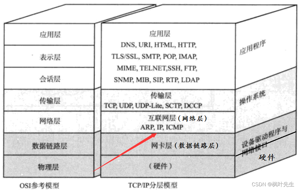
Problems solved by the network layer
- Transport layer: Responsible for data transmission between two hosts. Representative protocol: TCP protocol, ensuring datareliability is sent from the source host to the target host
- The data from the transport layer continues to be delivered down to the network layer
- Network layer: Responsible for address management and routing. Representative protocol: IP protocol, which identifies a host through its IP address and plans the data transmission line (routing) between the two hosts through the routing table
- TCP, as a transport layer control protocol, ensures the reliability of data transmission, but TCP only provides data transmission strategies , and the network layer and link layer below the transport layer are really responsible for data transmission in the network
The problem to be solved by the network layer is:Sending data from one host to another across the network, that is, data routing (path selection)
- The core function of the IP address is tolocate the host
- IP has the ability to send data from host A to host B across the network (host to host)
- Having the ability may not mean you can do it. For example, Zhang San has the ability to score 150 points on the math test, but he is not guaranteed to get 150 points every time. Having the ability means that there is a very high probability of completing it.
- TCP provides the strategy for sending data, and IP is responsible for providing the action (sending data)
- That is to say, the network layer cannot guarantee that the data can be successfully sent to the other host every time, but under the guarantee of the reliability policy provided by TCP, the network layer will eventually be able to reliably send the data to the other host.
basic concept
- Host: Each host is equipped with an IP address, but a device that does not perform routing control (now there are almost no devices that do not perform routing control)
- Router: Equipped with an IP address and capable of routing control (working at the network layer, some current routers already have application layer functions)
- Node: the collective name for hosts and routers
Path Selection
The network transmission of data is generally across networks, and routers are hardware devices that connect multiple networks. Therefore, data must pass through one or more routers when transmitting across networks.
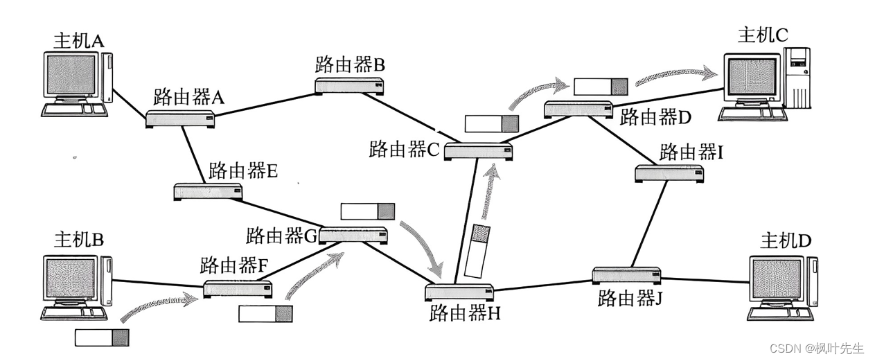
- For example, host B sends data to host C. After determining the address of host C (destination IP), the data can be routed (the destination IP determines the path, why choose this path instead of another path)
- However, the data cannot choose its own path when routing, because the data itself "does not know the path"
- Routers know how to take the road, and they record their "route recognition experience" in the routing table.
- Therefore, the router can find the shortest path to a specific node by looking up the routing table.
- Therefore, when data is routed, it will continue to select paths through routers to get closer to the target network or target host step by step.
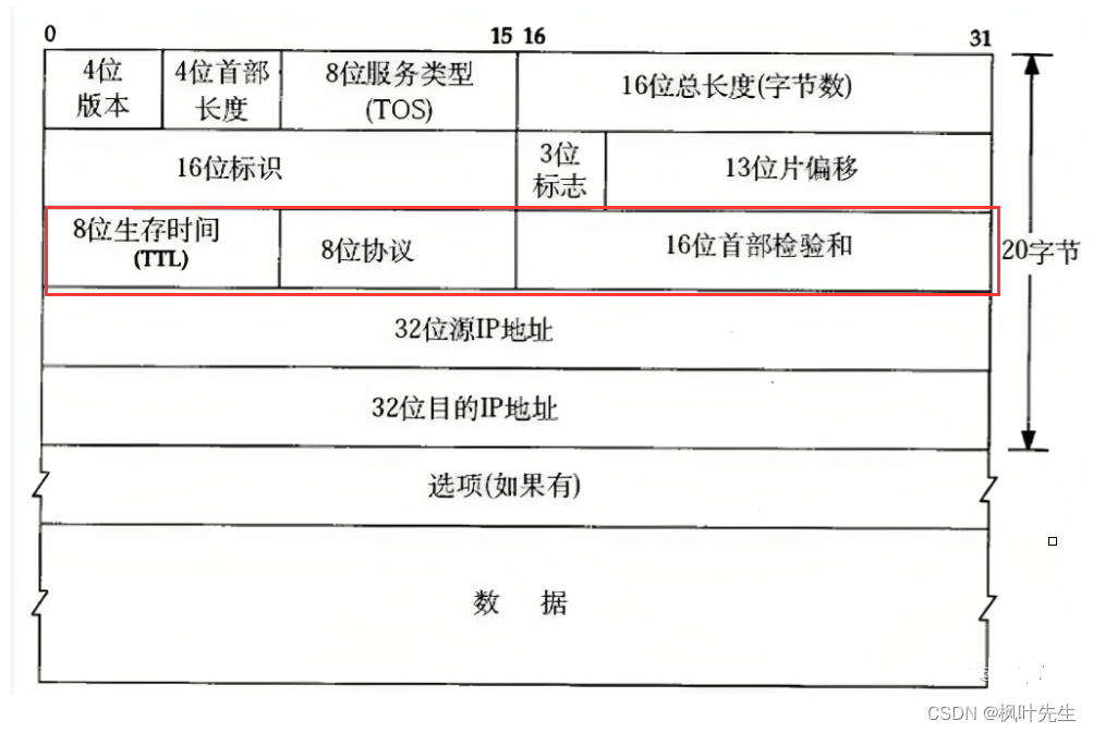
2. IP protocol header
The IP protocol header format is as follows:
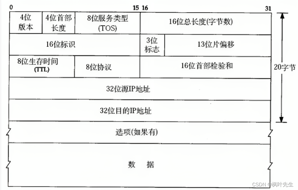
- 4-digit version number (
version): Specifies the version of the IP protocol. For IPv4, it is 4 - 4-bit header length (
header length): Indicates the length of the IP header, in units of 4 bytes (the maximum length of the IP header is 60 bytes, the base header length is 20 bytes) - 8-bit type of service (
Type Of Service): 3-bit priority field (deprecated), 4-bit TOS field, and 1 bit reserved field (must be set to 0). The 4-digit TOS respectively represents: minimum delay, maximum throughput, maximum reliability, and minimum cost. These four conflict with each other and only one can be chosen. For example, for applications such as ssh/telnet, the minimum delay is more important, while for programs such as ftp, the maximum throughput is more important. - 16-bit total length (
total length): The total length of the IP packet (IP header + payload), used to combine each IP packet Separate text - 16-bit identifier (
id): uniquely identifies the message sent by the host. If the data is fragmented at the IP layer, then each The ids corresponding to a shard are all the same - 3-digit flag field: The first bit is reserved. Reserved means that it is not used now, but it may be used in the future, but it has not been decided yet. The second bit indicates that fragmentation is prohibited, indicating that if the length of the packet exceeds
MTU, the IP protocol will discard the packet. The third bit represents "more fragments". If the message is not fragmented, this field is set to 0. If the message is fragmented, except for the last fragmented message, the remaining fragments are set to 0. The packets are all set to 1 (this field of the last fragmented packet is 0, similar to the end flag, similar to the C language string ending with'\0') - 13-bit slice offset (
framegament offset): The offset of the slice relative to the beginning of the original data, indicating that the current slice is in the original data The offset position, the actual number of offset bytes is obtained by this value× 8. Therefore, except for the last message, the length of other messages must be an integer multiple of 8, otherwise the messages will not be continuous - 8-bit survival time (
Time To Live,TTL): The maximum number of hops for a datagram to reach its destination, usually 64, each time it passes through a route ,TTL -= 1, if it is reduced until 0 is not reached, then it is discarded. This field is mainly used to prevent routing loops - 8-bit protocol: Indicates the type of upper layer protocol
- 16-bit header checksum: Use CRC for verification to identify whether the header of the datagram is damaged, but the data part is not checked
- 32-bit source IP address (
Source IP Address): Indicates the IP address of the source host that sent the datagram. - 32-bit destination IP address (
Destination IP Address): Indicates the IP address of the destination host receiving the datagram - Option field: variable length, up to 40 bytes (not discussed)
How to separate header and payload? ? i.e. how to unpack
The header of the IP protocol is similar to the header of the TCP protocol. When IP obtains a message from the bottom layer, although IP does not know the specific length of the header, the first 20 bytes of the IP message are the basic header of IP, and these 20 bytes Bytes include 4-bit header length
The process of IP unpacking is as follows:
- After IP obtains a message from the lower layer, it first reads the first 20 bytes of the message and extracts the 4-bit header length. At this time, the size of the IP header is obtained.
- Note: The length of the IP basic header is 20 bytes, and 20 bytes can be read without brain.
- The 4-bit header length in the IP header is only 4 bits, that is, the value range of the 4-bit header length is
0000 ~ 1111, that is, the maximum length is 15, and because the 4-bit header length The basic unit of length is 4 bytes, so15*4=60bytes - That is, the maximum length of the IP header is 60 bytes, and the basic length is 20 bytes. That is, the value range of the header is
[20 ~ 60] - The header also has a field of 16 bits total length: the total length of the IP message (IP header + payload)
- After getting the header length, you can directly separate it from the payload.
Note: Different protocol layers have different names for data packets. In the transport layer, it is called a data segment (segment), and in the network layer, it is called a datagram (datagram), called data frame (frame) at the link layer
How does IP decide which upper layer protocol to deliver the payload to? That is, how to use
- There is a field in the IP header called 8-bit protocol. This field (protocol number) represents the type of upper layer protocol. IP uses this field to determine which upper layer protocol the separated payload should be delivered to.
- NOTE: Each protocol has a specific number
How to unpack and separate has been solved, encapsulation is the other way around.
8-bit time to live
- During the network transmission process, the packet may not be able to reach the target host due to some reasons. For example, a loop routing occurs during routing of the packet. At this time, the packet becomes a discarded useless packet.
- In order to avoid a large number of useless packets in the network (useless packets waste router resources every time they are forwarded), a field appears in the IP header called the 8-bit survival time.
- The 8-bit survival time represents the maximum number of hops for a packet to reach its destination. Whenever a packet passes through a route, the survival time here will be reduced by one. When the survival time is reduced to 0, the packet will be automatically The router discards the packet, and the packet will dissipate in the network.
32-bit source IP address and 32-bit destination IP address
- The 32-bit source IP address and the 32-bit destination IP address play an important role in the routing and forwarding process (path selection)
- The router uses these two addresses to decide how to forward the packet. It looks up the routing table and finds the best path to send the packet from the source address to the destination address. This process is called routing and forwarding.
- Through the source IP address and destination IP address, the router can determine the starting point and end point of the data packet and select the best path for forwarding to ensure that the data packet can reach the destination quickly and accurately.
Let’s talk about the 16-bit identification (id), 3-bit flag field, and 13-bit slice offset at the end.
3. IP network segment division (subnet division)
The composition of an IP address
The IP address consists of two parts: network number and host number:
Network number: Ensure that the two network segments connected to each other have different identities
Host number: In the same network segment, hosts have the same network number, but different hosts must have different host numbers
There are two versions of the P protocol, IPv4 and IPv6. Any mention of the IP protocol in the postscript refers to IPv4 by default unless otherwise specified (IPv4 is not compatible with IPv6)
- For IPv4, the IP address is a 4-byte, 32-bit positive integer (32 bits)
- Add
/after the IP address, and add after/, which means The number from the beginning to the number belongs to the network identification (network number)数字
For example, the router in the figure below connects two network segments (subnets):
- For network labels, the network numbers of hosts in the same network segment are the same, and the network identifiers of hosts in different network segments are different.
- For host numbers, the host numbers of hosts in the same network segment are different, and the host numbers of hosts in different network segments can be the same.

- Different subnets actually put hosts with the same network number together.
- If a new host is added to the subnet, the network number of the host must be the same as the network number of the subnet, but the host number must not be the same as that of other hosts in the subnet.
- A router spans at least two subnets
Why do we need to divide IP network segments? ? (Why subnetting?)
- When sending data from one host to another across the network, instead of linearly traversing the IP address, the data is first sent to the network where the target host is located, then to the other party's target network, and then the data is Send to target host
- The reason for not linearly traversing IP addresses is because it is extremely inefficient. In terms of IPv4, there are about 4.2 billion IP addresses.
- The process of finding a host is essentially a process of elimination. If the purpose of finding the target host is from the beginning, then only one host can be excluded at a time during the search process.
- And if you first aim to find the target network, then during the search process you can exclude a large number of hosts that are not in the same network segment as the target host at once, which can greatly Improve search efficiency
for example:
- For example, our student ID number is carefully designed, and each field represents a different meaning.
- Each school has many colleges. Suppose the number of the School of Computer Science is 001, the number of the School of Science is 002, the number of the School of Electronic Information is 003, and the number of the School of Chemical Engineering is 004.
- Zhang San is a classmate of the School of Computer Science. Zhang San saw a wallet with only his student number on it
0030115. Zhang San didn’t recognize the student number, so Zhang San kept asking Ask the classmates who came over: What is your student number... - Suppose there are 20,000 people in the school and are unlucky. Zhang San has to ask all 20,000 people. This efficiency is extremely touching.
- At this moment, Zhang San had an idea flash in his head. Isn’t there a college number on it? He handed it directly to the administrator of his college, and then the administrator of his college handed it over The administrator of the college with the student number
0030115will then give it to the student with the student number0030115. Doesn’t this greatly improve the efficiency of search
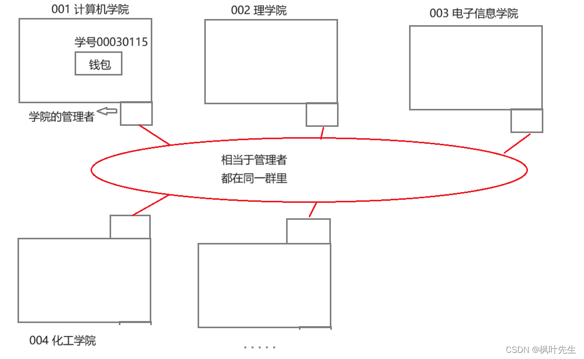
- Although Zhang San doesn’t know which college the student number is from,
- But when I looked at the management of the computer, I saw that it wasn’t from the School of Electronic Information, so I just handed it over to the managers of the School of Electronic Information.
- This kind of search process is actually an elimination process. According to different numbers (network segments), n groups of colleges (network segments) can be excluded at one time, which greatly improves the search efficiency.
- The administrator of a college is equivalent to a router, and each college is equivalent to a subnet.
Therefore, in order to improve the efficiency of data routing search, the IP address is divided into IP network segments (subnet division)
DHCP
By properly setting the host number and network number, you can ensure that the IP address of each host in the interconnected network is different.
- In the past, IPs needed to be managed manually. Manually managing IP addresses was a very troublesome thing. When a new host was added to the subnet, it needed to be assigned an IP address. When a host in the subnet disconnected from the network, its IP address needed to be assigned. The address is recycled so that it can be allocated to subsequent newly added hosts.
- The DHCP protocol appeared later
- DHCP (
Dynamic Host Configuration Protocol, Dynamic Host Configuration Protocol) is a LAN network protocol that uses UDP protocol and has two main uses: automatic allocation to internal networks or network service providers IP addresses, given to users or internal network administrators as a means of central management of all computers - DHCP is an application layer protocol based on UDP. Generally, routers have DHCP function, so the router can also be regarded as a DHCP server.
When your device is successfully connected to WiFi, the router will automatically assign an IP to your device, and then your device will have an IP address and can access the Internet (devices that are not connected to the Internet do not have an IP address)
Who does subnetting? ?
- The Internet is a designed world, and IP addresses are also designed.
- For our country, operators (China Mobile, China Telecom, China Unicom) are the executors of subnet division and the designers of the underlying network.
How to divide network segments? ? (How to subnet)
In the past, a solution was proposed to divide network numbers and host numbers, which was to divide all IP addresses into five categories
As shown in the figure below:
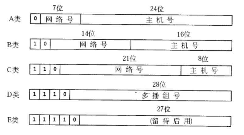
Therefore, the value ranges of various IP addresses are as follows:
- A category:
0.0.0.0to127.255.255.255 - B category:
128.0.0.0to191.255.255.255 - C category:
192.0.0.0to223.255.255.255 - D category:
224.0.0.0to239.255.255.255 - E category:
240.0.0.0to247.255.255.255
To determine which type of network an IP address belongs to, you can determine it by looking at the first byte of the IP address (the first 8 bits)
CIDR (Classless Interdomain Routing)
However, with the rapid development of the network, the limitations of this division scheme soon became apparent.
- For example, if you apply for a Class B address, theoretically more than 65,000 hosts can be allowed in a subnet. For Class A addresses, the number of hosts in the subnet is even greater.
- However, in actual network construction, there will not be so many in one subnet. Therefore a large number of IP addresses are wasted
In order to avoid this situation, a new division scheme was proposed, called CIDR (Classless Interdomain Routing). CIDR is an IP address allocation and routing strategy aimed at more Effectively utilize IPv4 addresses
- Continue to divide subnets on the basis of the original five types of networks, which means that several bits of the host number need to be borrowed to serve as the network number. At this time, in order to distinguish the network number and host number in the IP address No., so the concept of subnet mask (
subnet mask) was introduced - Each subnet has its own subnet mask. The subnet mask is actually a 32-bit positive integer, usually ending with a string of "0"
- Use the IP address and the subnet mask of the current network to perform the "
按位与" operation to get the network number of the current network - The division of network number and host number here has nothing to do with whether the IP address is Class A, Class B or Class C.
At this time, a network is divided into smaller subnets in a more fine-grained manner. Through continuous subnet division, the host number corresponding to the IP address in the subnet becomes shorter and shorter, so the available IP addresses in the subnet The number of IP addresses will become smaller and smaller, which will avoid a large amount of waste of IP addresses.
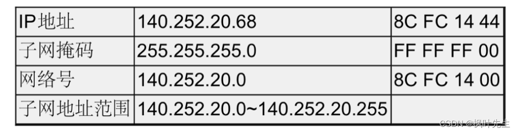
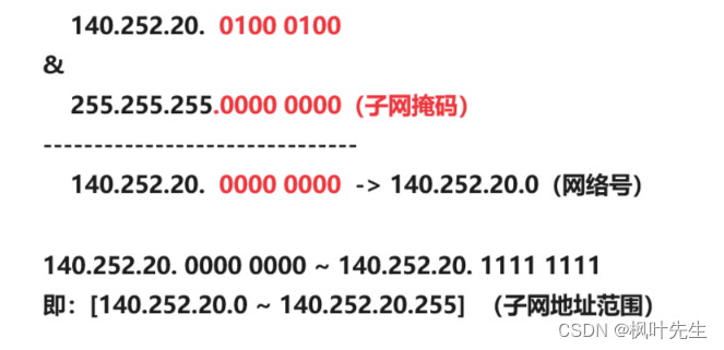
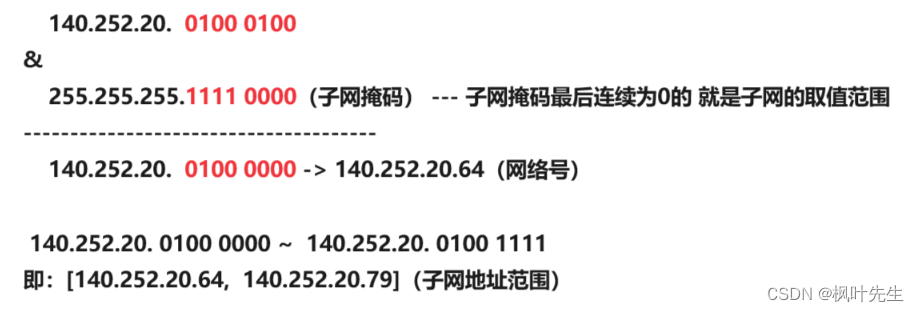
Examples of subnetting are as follows:
- The IP address and subnet mask are bitwise ANDed to get the network number of the network.
- The host number from all 0 to all 1 is the address range of the subnet
Another example:
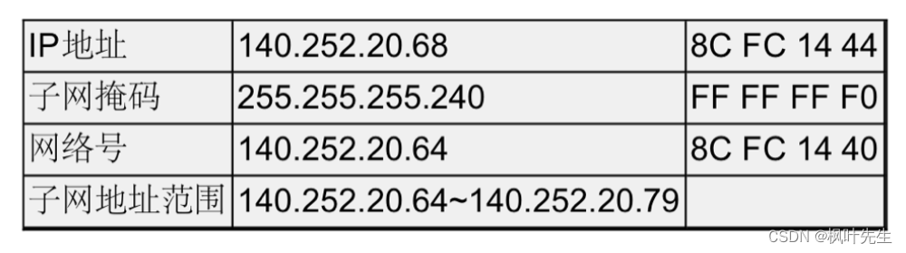
It should be noted that subnetting can not only be done once, but can be continued based on the divided subnets.
- Generally in a subnet, the device that manages the IP in the subnet is usually a router.
- The destination network, subnet mask, and hosts in the subnet are all managed by the router.
- The target network and subnet mask are configured on the router
4. Special IP address
Not all IP addresses can be used as host IP addresses. Some IP addresses themselves have special purposes.
- Set all the host addresses in the IP address to 0, which becomes the network number, representing this LAN. For example,
140.252.40.0or140.252.40.64in the above picture, this address represents the network number and cannot be assigned to the host - Set all the host addresses in the IP address to 1, which becomes a broadcast address and is used to send data packets to all hosts connected to each other on the same link. For example,
140.252.40.255or140.252.40.79in the above picture, this address represents the broadcast address and cannot be assigned to the host 127.*The IP address of is used for native loopback (loop back) testing, usually127.0.0.1
broadcast address
- The broadcast address is used to send packets between hosts connected to each other on the same link (broadcast to all hosts in the same subnet)
- A broadcast address is an address designed to send to all workstations on the network (usually the same subnet) at the same time.
- When the host number is all 1, it represents the broadcast address of the network
- For example, during class, the monitor shouts "Class, everyone, stand up!", and the students in the class all stand up after hearing it. This command has the meaning of broadcasting.
local loopback
- Local loopback is a special network interface usually used for internal communication and management of network devices
- The local loopback interface belongs to a special category of IP addresses, called the loopback address, usually designated as the 127.0.0.0/8 network segment, the most common of which is 127.0.0.1
- Local loopback It can be used not only for remote management and troubleshooting, but also for testing network services and internal communications
5. Limitation on the number of IP addresses
IP address (IPv4) is a 4-byte 32-bit positive integer, so there are 2^32 IP addresses in total, which is nearly 4.3 billion IP addresses. However, the TCP/IP protocol stipulates that each host needs an IP address
- There are now more than 7 billion people in the world. Even if half of the people do not have smartphones, there are still more than 3 billion smartphones that require IP addresses.
- With the development of technology, the computers, smart watches, smart refrigerators, smart washing machines and other devices we use also need IP addresses if they want to access the Internet.
- In addition, IP addresses are not configured according to the number of hosts, so a host may require multiple IP addresses, not to mention that there are many routing devices in the network that also require IP addresses, and some special IP addresses cannot be used.
Therefore, the 4.3 billion IP addresses are actually not enough for a long time. Therefore, the CIDR solution was proposed to continue to subnet the five types of networks that have been divided. The purpose is to reduce the waste of IP addresses. The fundamental reason is that the IP addresses are inherently It’s not enough, so we can’t waste it anymore.
Although CIDR alleviates the problem of insufficient IP addresses to a certain extent because CIDR improves the utilization of IP addresses and reduces waste, the absolute upper limit of IP addresses has not increased and is still around 4.3 billion.
Three ways to resolve IP addresses
- Dynamic IP address allocation: Only assign IP addresses to devices connected to the network. Therefore, devices with the same MAC address will get different IP addresses each time they connect to the Internet. It must be the same to avoid the IP address being forcibly bound to a certain device
- NAT technology: It can allow two identical IP addresses to exist in different LANs at the same time. NAT technology can not only solve the problem of insufficient IP addresses, but also effectively prevent the network from entering the network. External attacks, hiding and protecting computers inside the network
- IPv6: IPv6 uses 16 bytes and 128 bits to represent an IP address, which can greatly alleviate the problem of insufficient IP addresses. But IPv6 is not a simple upgraded version of IPv4. They are two unrelated protocols and are not compatible with each other. Therefore, IPv6 is not yet popular
my country is currently doing relatively well with IPv6, but its promotion has been delayed due to incompatibility with IPv4. Because IPv4 is embedded in the OS and the underlying facilities are incompatible with IPv6, it is difficult to promote IPv6.
Due to the emergence of NAT technology, the problem of insufficient IP addresses has been solved, but the absolute upper limit of IP addresses has not increased (NAT technology still has not completely solved this problem)
Although the emergence of NAT technology has hindered the development of IPv6, it has also helped the promotion of IPv6 in my country. Through NAT technology, IPv6 addresses can be converted into IPv4 addresses. At present, the intranet environment of most Internet companies in my country is IPv6
Although the United States is also engaged in IPv6, it has no motivation (why should I overturn IPv4 when I have nothing to do)
To completely solve the problem of insufficient IP addresses, we still need to rely on IPv6
6. Private IP address and public IP address
If an organization establishes a LAN internally, the IP address is only used for communication within the LAN and is not directly connected to the Internet. In theory, any IP address can be used, but RFC 1918 stipulates the private IP address used to establish a LAN:
10., the first 8 digits are the network number, a total of 16,777,216 addresses172.16.to172.31., the first 12 digits are the network number, a total of 1,048,576 addresses192.168., the first 16 digits are the network number, a total of 65,536 addresses- Those included in this range are called private IP (private IP, intranet IP), and the rest are called public IP (or global IP)
Check the IP of your host
ifconfig: This command is used to display and configure network interface information.
For example, if you purchased a Linux server, enter this command
eth0Represents: Usually represents the first Ethernet interface of the system. It is a physical network interface used to connect to a local area network or the Internet. eth0 can be a wired or wireless Ethernet interface, depending on your system setup and network hardwarelois the local loopback interface (loopback interface), also known as the loopback address. It is a virtual network interface used for system internal communication. The IP address of the lo interface is usually127.0.0.1, and the subnet mask is255.0.0.0. It allows communication between processes and services within the system without going through a physical network interface- In the picture
eth0, the corresponding addressinetin the interface192.168.0.213is the private IP
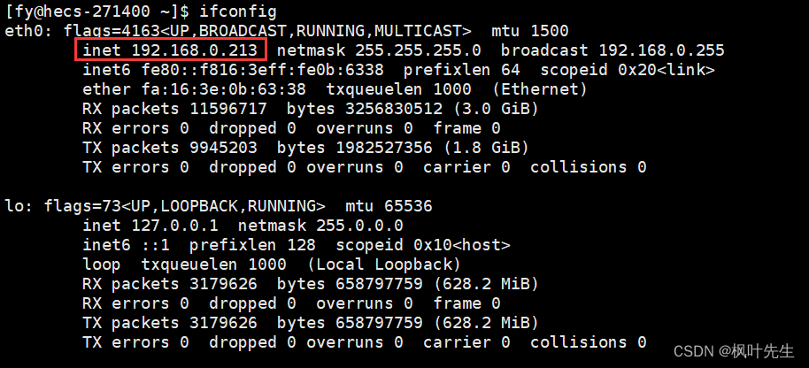
The IP used to connect to the Linux server is called the public IP
Note: Check the usage command under Windowsipconfig
Why do we have to pay the operator? ?
What we enjoy are services provided by Internet companies, such as browsing Douyin, buying things on Taobao... But we do not pay money to Internet companies (the cost of Internet access), but hand over the money to the operators. Why do we pay the money? Give it to operators instead of Internet companies. We are obviously enjoying various services provided by Internet companies? ?
- Operators are the builders of network communication infrastructure. When we access the Internet, various data (request and response data) must go through the operator.
- In other words, our data request to access the server is not sent directly to the corresponding server, but needs to be forwarded by various base stations and various routers and clusters built by the operator before the data can finally reach the corresponding server.
- The data that the corresponding server responds to us must also go through the operator and be forwarded by the operator before the final response reaches our client.
- When we pay the network fee to the operator, it is actually equivalent to purchasing a network access license (allowing us to access the Internet), because we must use the communication infrastructure provided by the operator, and we cannot access the Internet without using it.
For example, if your mobile phone number is in arrears and you still want to access the Internet, when you go through the operator, the operator will authenticate your account and find that you are in arrears, directly discarding your request and not forwarding it to the corresponding party. server
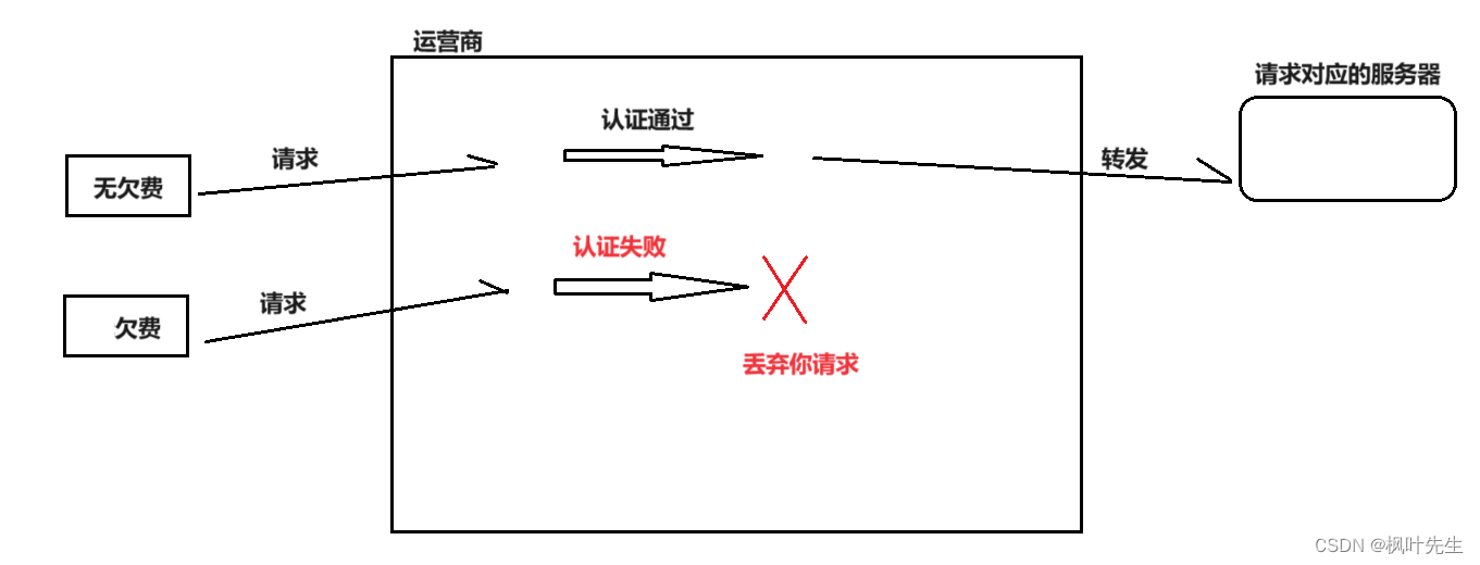
- On the contrary, if Internet companies want to access the Internet, they must pay fees to the operator, otherwise they will not be able to access the Internet, that is, the data from the server cannot be sent to the client.
- The operator is equivalent to playing the role of a middleman, charging both parties.
- The so-called network segmentation and subnet division are actually done by the operators.
- Without these infrastructures provided by operators, so-called Internet companies would not be born, because Internet companies are born on the basis of network communications.
- In the same way, since our datagrams must pass through the operator, the operator can detect our data packets. If it is found that the URL you requested is an illegal URL or the data packet accesses an external network, such as Google, Twitter, etc., The operator will directly fork your request and not forward your data packet.
In other words, the data used by users to access the Internet must first pass through the relevant network equipment of the operator, and then can be sent to the corresponding server of the Internet company. Therefore, if we want to access the Internet, we must pay the operator.
Router functions
- Data forwarding
- DHCP and setting up a LAN (subnet)
- NAT
Routers are divided into home routers and enterprise routers:
- The IP used to set up a LAN must be a private IP, and public IP cannot be used.
- Home version router: low power, suitable for daily use. The private IP used to build a LAN is usually
192.168. - Enterprise-level router: The private IP used to build a LAN is usually
10.or172.16.to172.31.
How data is sent to the corresponding server
A router is a hardware device that connects two or more subnets. There are two network interfaces on the router, namelyLAN口 and WAN口:< /span>
LAN口(Local Area Network): Indicates the port connected to the local network, mainly connected to the switch, hub or PC in the home networkWAN口(Wide Area Network): The table can be understood as the interface connecting to the public network, generally referring to the Internet.
We call the IP address of the LAN port the LAN port IP (internal), also called the subnet IP, and the IP address of the WAN port we call the WAN port IP, also called the external IP (external).
The relationship between the computers we use, home routers, carrier routers, WANs, and the servers we want to access are roughly as follows:
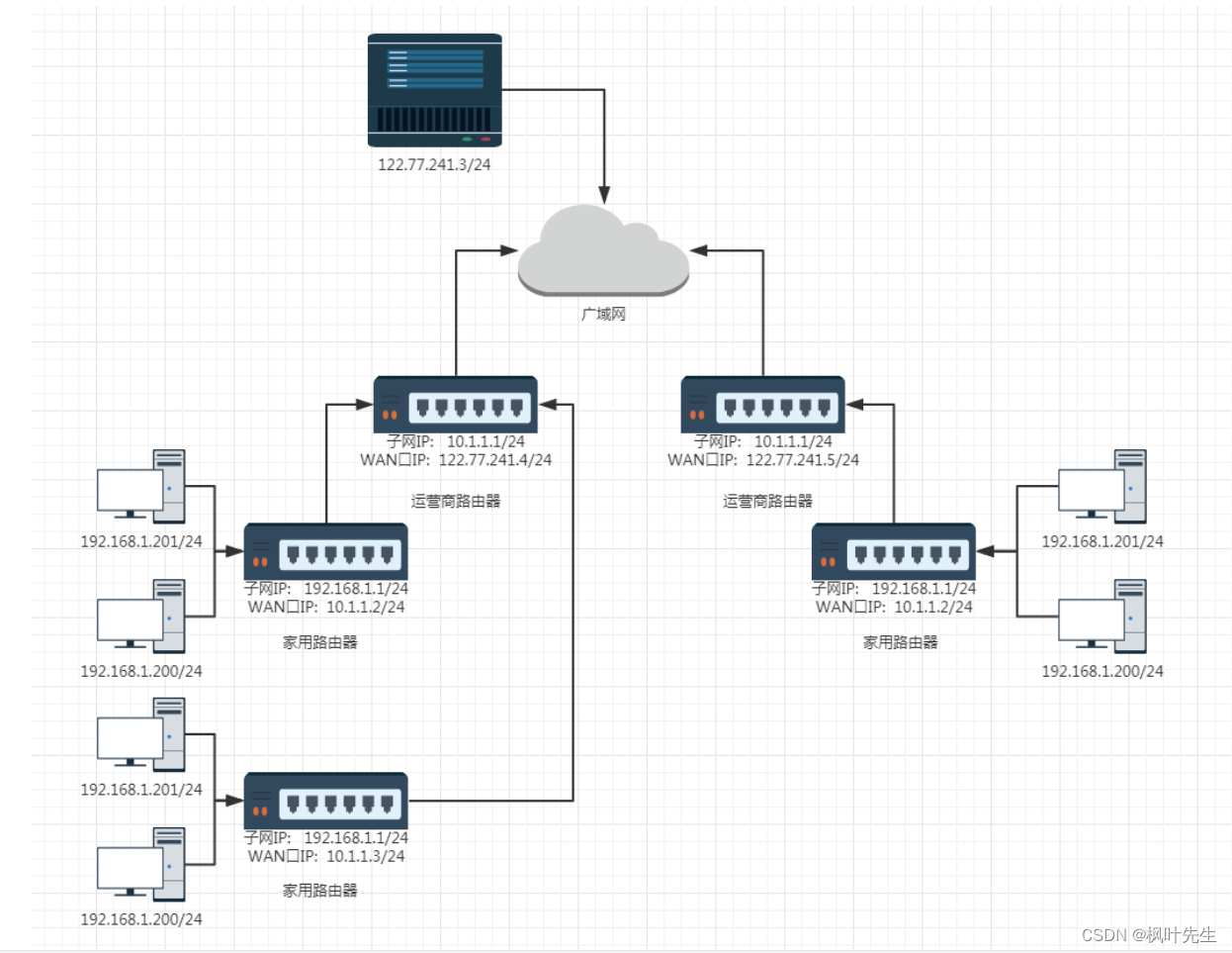
- Different routers have the same subnet IP (usually
192.168.1.1). The host IP addresses within the subnet cannot be repeated, but the IP addresses between subnets cannot be repeated. You can repeat it - Every home router is actually a node in the subnet of the operator's router. Such operator routers may have many levels. The WAN port IP of the outermost operator router is a public network IP.
- If we want the server program we implemented ourselves to be accessible on the public network, we need to deploy the program on a server with an external network IP. Such a server can be purchased on Alibaba Cloud/Tencent Cloud
Note:Private IP cannot appear in the public network
Why can't private IP appear in the public network?
- Private network IPs can be repeated, which means we can use the same IP address in different LANs, which alleviates the shortcomings of IP
- That is to say, the private IP address is not unique globally. If it is used directly on the public network, it will cause routing confusion. Therefore, if a private IP address wants to access the external network, it will go through the router and perform address translation, converting the private IP (unique to the local area network) into a public IP (unique to the world).
Since the private IP cannot appear on the public network:
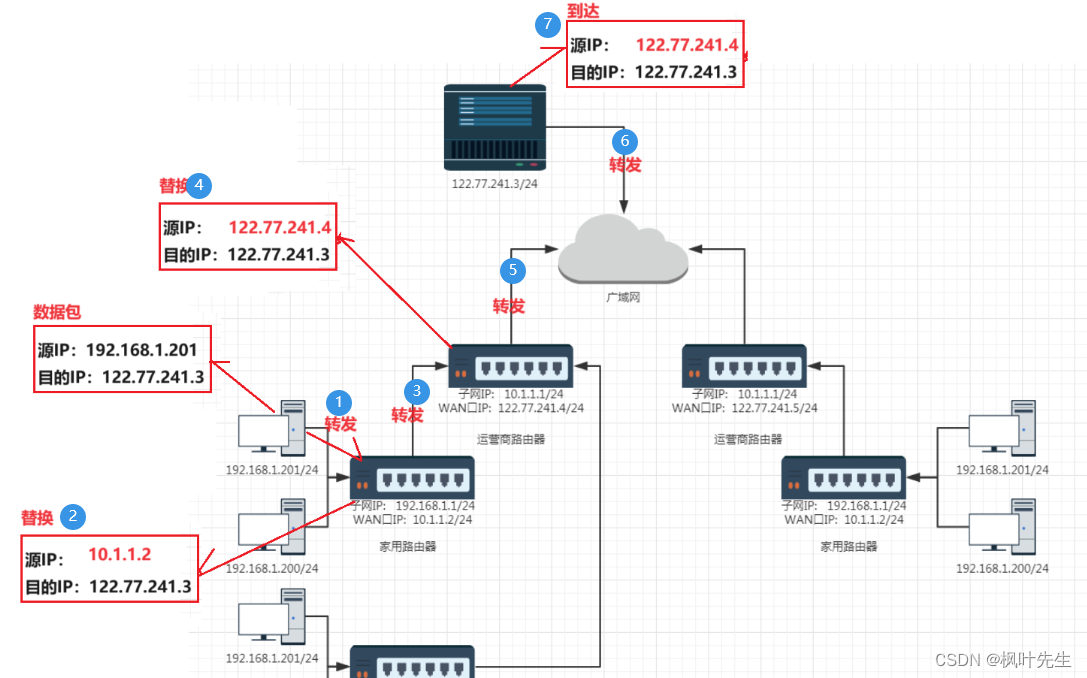
- Therefore, when the host in the subnet communicates with the external network, the router will continuously replace the
源IP地址in the IP header of the data packet with the router'sWAN口IP, such a step-by-step replacement, the source IP address in the final data packet becomes a public network IP, this technology becomesNAT(Network Address Translation, network address translation, Convert private address to legal IP address)
The general process of data forwarding is as follows:
- Assume the packet is going to
122.77.241.3/24 - After the data packet is sent from its own host to the home router, the router finds that the destination IP is no longer in its own subnet.
- will be replaced at this time
源IPby the routerWAN口IP, and then forwarded to another subnet directly connected to itself - Assume that the forwarded data packet reaches the operator's router, undergoes multi-level forwarding (passing through multiple subnets of the operator), and finally finds that the destination IP of the data packet is not within its own subnet.
- Replace at this time, and then forward the data packet directly to the public network
源IPwith the router'sWAN口IP - Then forwarded by the public network to the corresponding destination IP
As shown in the figure:
We will talk about how the data packets come back later
7. Routing
The process of data packet routing (similar to the process of asking for directions, one by one)
- During the routing process, the data packet is actually hop by hop, similar to the process of "asking for directions"
- The so-called "one hop" is an interval in the data link layer, specifically in Ethernet it refers to the frame transmission from
源MAC地址to目的MAC地址interval
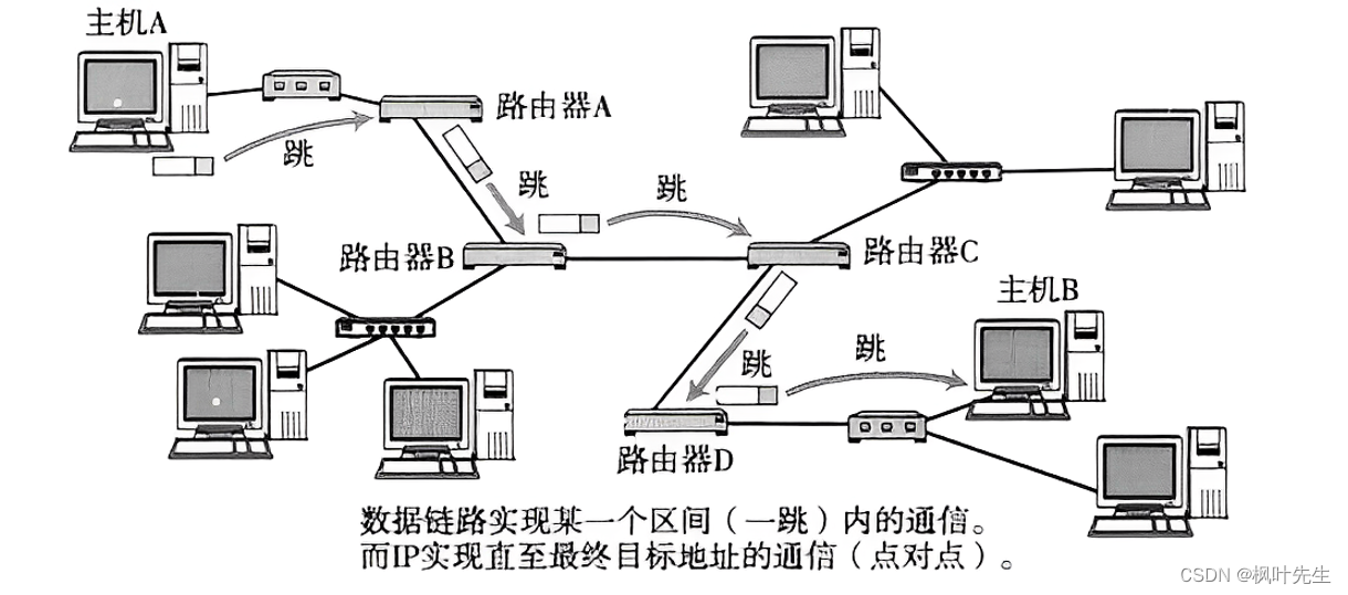
The transmission process of IP data packets is the same as asking for directions. During the transmission process of IP data packets, many routers will be encountered.
These routers will help route and forward data packets. Whenever a data packet encounters a router, the corresponding router will check the destination IP address of the data and tell where the next hop of the data should be.
- When an IP data packet reaches the router, the router will first check the destination IP
- The router decides whether the data packet can be sent directly to the target host or needs to be sent to the next router (check the routing table)
- Repeat in sequence until reaching the target IP address
How to determine where the current data packet should be sent?
- This relies on each node (router) maintaining a routing table internally.
- By checking the routing table, you can know who the data table should be sent to.
目的IPin the IP packet, the search results in the router's routing table may have the following three types:
- After querying the routing table, the router learns which subnet the next hop of the data should jump to.
- After querying the routing table, the router does not find a matching subnet. At this time, the router will forward the data to the default route (default gateway).
- After querying the routing table, the router learns that the target network of the data is the current network. At this time, the router will transfer the data to the corresponding host in the current network.
View routing table
The routing table can be viewed using theroute command, which can display the routing table of the current system
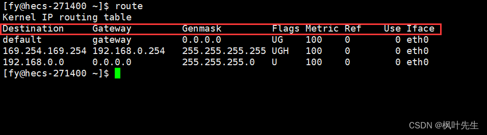
Explanation of the entry part:
Destination: IP address of the target network or hostGateway: The IP address of the next-hop gateway, that is, the next-hop router that sends the packet to the target network or host.Genmask: The netmask of the target network or hostFlags: Flag bit used to indicate the status and attributes of routing table entries. Common flag bits include U (the routing table entry is available), G (the routing table entry is specified by the gateway, indicating that the next hop address of this entry is the address of a router), H (the routing table entry is a host routing)Iface:Interface, indicating which network interface the packet will be sent through
What some of these fields mean:
default: Indicates that this is the default route (gateway), that is, when the system cannot find a matching target network or host, this routing table entry will be used0.0.0.0: Indicates that the target network or host is any network or hostUG: Indicates that this is a default routing table entry and the gateway field is valid. Entries without the G flag indicate that the destination network address is a network directly connected to the local interface and does not need to be forwarded by a router.
The process of checking the routing table
-
When the IP data packet reaches the router, the router will check the destination IP address of the data packet, and perform "bitwise AND" with the subnet mask in the routing table
Genmaskoperation (traverse the routing table), and then compare the result with the destination network addressDestinationcorresponding to the subnet mask. If it matches, it means that the next hop of the data packet should jump to this subnet. , the data packet will be sent out through the corresponding sending interfaceIface -
If no matching destination network address is found after performing a "bitwise AND" between the destination IP address of the packet and the subnet mask, the router will send the packet to the default route. It is
defaultin the destination network address in the routing table. You can see that the correspondingFlagsof the default route isUG, which actually transfers the data to another router and allows the data to continue on the other router. Routing -
After the data packet is continuously routed through the router, it will eventually reach the target network where the target host is located. At this time, the data packet is no longer routed based on the network number in the destination IP address, but based on the host number in the destination IP address. Routing, and finally the data can be sent to the target host according to the host number corresponding to the data packet.
The routing table can be manually maintained by the network administrator (static routing) or automatically generated through some algorithms (dynamic routing)
Routing table generation algorithm: distance vector algorithm, LS algorithm, Dijkstra algorithm, etc.
Notice:The IP protocol at the network layer provides decisions for data routing, and the real The data is forwarded by the data link layer (the one that actually does the work)
Finally, add the 16-bit identification (id), 3-bit flag field, and 13-bit slice offset that were not mentioned above.
8. Fragmentation and assembly
The following explains the 16-bit identification (id), 3-bit flag field, and 13-bit slice offset
This will involve data link layer issues
- IP can send data packets from one host to another across the network. When the data packets are transmitted across the network, they need to be routed and forwarded by routers before they can finally reach the target host.
- Therefore, the premise for IP to transmit data packets across the network is thatit needs to first transmit the data packet from one node to the next node connected to itself, this problem is actually solved by the data link layer under IP, where the representative protocol of the data link layer is the MAC frame protocol
- That is, the data link layer is responsible for communicating between adjacent nodes, encapsulating data packets into frames, and transmitting them through the physical medium
- The direct connection of two nodes means that the two nodes are in the same LAN. Therefore, when discussing the data transmission of two adjacent nodes, what is actually discussed is the issue of LAN communication.
Maximum transmission unit MTU
- MAC frame is a data link layer protocol. It encapsulates the data transmitted from IP into data frames and then sends them to the network (data frames run on the network cable). However, the MAC frame protocol has a limit on the size of the data transmitted. , this value cannot be exceeded when transmitting data frames. This value is called MTU, maximum transmission unit.
- Maximum transmission unit (
Maximum Transmission Unit,MTU) refers to the size of the largest data frame that the data link layer can transmit in network communication. The size of the MTU is usually specified by the network device or network protocol, and it limits the amount of data that can be transferred at one time - The default MTU size is generally 1500 bytes
Use the ifconfig command under Linux
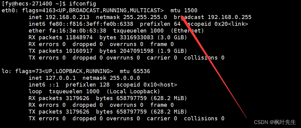
- MAC frame protocol cannot send data larger than 1500 bytes
- Therefore, the length of the data packet delivered down by the IP layer cannot exceed 1500 bytes, and
IP报头+有效载荷 <= 1500字节 - If it is larger than 1500 bytes, the MAC frame protocol cannot send the data
- If the data to be sent by the IP layer exceeds 1500 bytes, the data needs to be fragmented at the IP layer first, and then the fragmented data is handed over to the lower layer MAC frame for transmission.
- Because the IP protocol cannot control the size of a message sent, the size of a message sent is controlled by the transport layer protocol (TCP or UDP)
Since there is fragmentation, there must also be assembly. Fragmentation and assembly are completed at the IP layer. Fragmentation and assembly are purely actions of the IP protocol and have nothing to do with the upper transport layer and the lower data link layer.
Notice:IP fragmentation and assembly is not a mainstream situation, IP fragmentation and assembly is a special situation, the mainstream situation will be discussed in the next article Article: Let’s talk about the data link layer again
How to slice and assemble? ?
Fragmentation and assembly can be completed by relying on these three fields:
- 16-bit identifier (
id): uniquely identifies the message sent by the host. If the data is fragmented at the IP layer, then each The ids corresponding to a shard are all the same - 3-digit flag field: The first bit is reserved. Reserved means that it is not used now, but it may be used in the future. The second bit indicates that fragmentation is prohibited, indicating that if the length of the packet exceeds
MTU, the IP protocol will discard the packet. The third bit represents "more fragments". If the message is not fragmented, this field is set to 0. If the message is fragmented, except for the last fragmented message, the remaining fragments are set to 0. The packets are all set to 1 (this field of the last fragmented packet is 0, similar to the end flag, similar to the C language string ending with'\0') - 13-bit slice offset (
framegament offset): The offset of the slice relative to the beginning of the original data, indicating that the current slice is in the original data The offset position, the actual number of offset bytes is obtained by this value× 8. Therefore, except for the last message, the length of other messages must be an integer multiple of 8, otherwise the messages will not be continuous
Notice: Fragmented packets must be re-encapsulated with IP headers
How to know whether an IP packet is fragmented?
- The third flag bit in the 3-bit flag field indicates "more fragmentation". If the message is not fragmented, this field is set to 0. If the message is fragmented, except for the last fragmented message, Except for the packets set to 0, the other fragmented packets are set to 1.
How can fragments of the same message be identified?
- Through the 16-bit identification, the 16-bit ID of the fragmented packets is the same.
How to determine which fragmented packet is the first and which is the last?
- The last fragmented message can be known through the third flag bit, more fragments and the fragment offset, that is, changing
多分片标志位为0 && 片偏移>0represents the last fragmented message a> - The first fragmented message is judged by
多分片标志位为1 && 片偏移 == 0. If it is satisfied, it is the first fragmented message
How to know whether the fragmented packets have been collected? How to assemble, which fragmented message comes first and which split message comes last?
- Whether the fragmented message is fully received is judged by the 13-bit fragment offset (current starting position + own length == offset size filled in the next fragmented message). If the fragmented message is incomplete, it is directly Discard and let the peer TCP resend the entire message.
- How to assemble is also determined by the 13-bit slice offset. Just sort the slice offsets of the fragmented messages in ascending order.
How to ensure that the assembled message is correct?
- Passed 16-bit header inspection and judgment
- When delivered to the upper layer TCP/UDP, TCP/UDP will also be judged by TCP/UDP's own 16-bit header inspection and judgment.
- If the verification fails, the packet is discarded directly.
Data fragmentation and assembly are completed by the IP layer
- The fragmentation and assembly of data are completed at the IP layer, and the upper transport layer and lower link layer do not care.
Is sharding good?
The answer is, it is definitely not good. Although the transport layer does not care about the fragmentation problem of the IP layer, fragmentation also has an impact on the transport layer.
- If a piece of data is fragmented during network transmission, then only when the receiving end receives all the fragmented messages and successfully assembles them, will we consider that the data has been reliably received by the other party.
- However, if one of the many fragmented messages is lost, the receiving end will be unable to successfully assemble the message. At this time, the receiving end will discard all received fragmented messages. Transport layer TCP will resend the message (entire)
- Fragmentation increases the probability of packet loss
- Assume that the probability of no packet loss is
99.99%. A message is fragmented at the IP layer and divided into three fragmented messages. At this time, the probability of packet loss is will increase,99.99%*99.99%*99.99% < 99.99%
How to reduce sharding?
The fundamental reason for actual data fragmentation is that the transport layer delivers too much data at one time, causing IP to be unable to directly hand the data down to the MAC frame. If the transport layer controls the amount of data delivered to IP at one time not to be too large, then Naturally, the data does not need to be fragmented at the IP layer.
- Therefore, as a transmission control protocol, TCP needs to control that the data delivered downwards at one time cannot exceed a certain threshold. This threshold is called MSS (Maximum SegmentSize, maximum segment length). The communicating parties will negotiate the MSS when establishing a TCP connection.
- The maximum payload of a MAC frame is MTU, and the maximum payload of TCP is MSS.
- Generally, the value of MSS is equal to the MTU minus the length of the IP and TCP protocol headers, because the lengths of the IP and TCP protocol headers are generally 20 bytes. The MTU of the MAC frame is generally 1500 bytes,
MSS = MTU - 20 - 20, so the MSS value is generally 1460 bytes - Therefore, in order to avoid data fragmentation, it is recommended that TCP control the data sent within the size of the MSS
- However, it should be noted that the MTU of different network links may be different. If the data passes through a network with a smaller MTU during transmission, it may still need to be fragmented.
In summary, the actual reason for data fragmentation is that the transport layer delivers too much data at one time. In order to avoid data fragmentation, the size of the data sent by TCP needs to be controlled within MSS.
The process of sharding
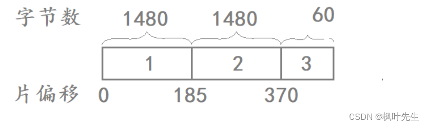
Assume that the IP layer wants to send 3000 bytes of data (IP header + payload). Since the data exceeds the MTU (1500) specified in the MAC frame, IP needs to fragment the data first, and then fragment it one by one. The fragment is handed over to the MAC frame for transmission.
Assume that the length of the IP header added by the IP layer is 20 bytes, and the data is fragmented as follows to form three fragmented messages:
| Fragmented message | Total number of message bytes | IP header bytes | Payload | 16-bit identifier | More shard flags | 13-bit slice offset |
|---|---|---|---|---|---|---|
| 1 | 1500 | 20 | 1480 | Assume it is 111 | 1 | 0 |
| 2 | 1500 | 20 | 1480 | 111 | 1 | 185 |
| 3 | 60 | 20 | 40 | 111 | 1 | 370 |
Notice: The number of bytes recorded in the 13-bit slice offset is the value of the offset bytes of the current slice at the beginning of the original data Most of the assembly issues have been discussed above, so I won’t go into details. The next article will enter the MAC frame protocol of the data link layer÷ 8
「 作者 」 枫叶先生
「 更新 」 2023.10.14
「 声明 」 余之才疏学浅,故所撰文疏漏难免,
          或有谬误或不准确之处,敬请读者批评指正。