Table of contents
2. IP address and hardware address
3. Address Resolution Protocol ARP
3.1 Introduction to ARP protocol
3.3 Four typical situations of ARP
4. Forwarding flow of IP protocol
1. Overview of IP
1.1 Introduction to IP
IP address (Internet Protocol Address) refers to the Internet Protocol address, also translated as Internet Protocol address.
The IP address is a unified address format provided by the IP protocol. It assigns a logical address to each network and each host on the Internet to shield the differences in physical addresses.
1.2 IP protocol
The IP protocol is a protocol designed for computer networks to communicate with each other. In the Internet, it is a set of rules that enables all computer networks connected to the Internet to communicate with each other, and stipulates the rules that computers should abide by when communicating on the Internet. Computer systems produced by any manufacturer can interconnect with the Internet as long as they comply with the IP protocol. The IP protocol is actually a set of protocol software composed of software programs. It uniformly converts various "frames" into "IP datagram" format. This conversion is one of the most important features of the Internet, enabling all kinds of computers to All can achieve interoperability on the Internet, that is, they have the characteristics of "openness" (Baidu Encyclopedia).
2. IP address and hardware address
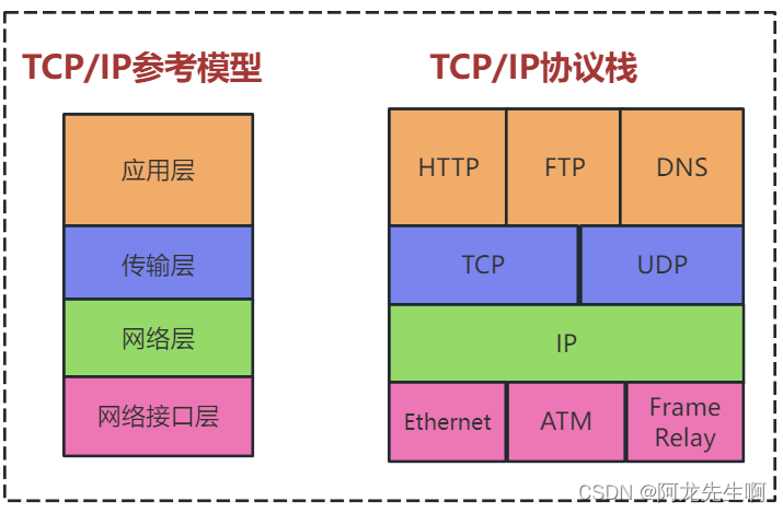
When learning IP addresses, it is important to understand the difference between the host's IP address and the hardware address.
The image above illustrates the difference between these two types of addresses. From a hierarchical perspective, the physical address is the address used by the data link layer and the physical layer, while the IP address is the address used by the network layer and the above layers. It is a logical address (the IP address is called a logical address because the IP address is implemented using software).
When sending data, the data flows from the upper layer to the lower layer and then is transmitted on the communication link. Once the IP datagram using the IP address is handed over to the data link layer, it is encapsulated into a MAC frame. The source address and destination address used when transmitting MAC frames are both hardware addresses, and both hardware addresses are written in the header of the MAC frame.
When a device (host or router) connected to a communication link receives a MAC frame, it decides to accept or discard it based on the hardware address in the MAC frame header. Only after stripping off the header and trailer of the MAC frame and handing over the MAC layer data to the network layer can the network layer find the source IP address and destination IP address in the header of the IP datagram. In short, the IP address is placed in the header of the IP datagram, and the hardware address is placed in the header of the MAC frame. IP addresses are used at the network layer and above, while hardware addresses are used at the data link layer and below. In the figure above, when the IP datagram is put into the MAC frame of the data link layer, the entire IP datagram becomes the data of the MAC frame, so the IP address of the datagram is not visible at the data link layer.
As shown in the figure below, three LANs are interconnected using two routers R1 and R2. Now host H1 wants to communicate with host H2. The IP addresses of these two hosts are IP1 and IP2 respectively, and their hardware addresses are HA1 and HA2 respectively (HA stands for Hardware Address). The communication path is: H1 → forwarded by R1 → forwarded by R2 → H2. Router R1 is connected to two LANs at the same time, so it has two hardware addresses, HA3 and HA4. Similarly, router R2 also has two hardware addresses HA5 and HA6.

Source addresses and destination addresses at different levels and intervals in the figure below
| - |
at the network layer The address written into the IP datagram header |
at the data link layer The address written into the IP datagram header |
||
| source address |
Destination address |
source address |
Destination address |
|
| From H1 to R1 |
IP1 |
IP2 |
HA1 |
HA3 |
| from R1 to R2 |
IP1 |
IP2 |
HA4 |
HA5 |
| From R2 to H2 |
IP1 |
IP2 |
HA6 |
HA2 |
The following points should be emphasized here:
(1) Only IP datagrams can be seen on the Internet where the IP layer is abstracted. Although the IP datagram has to be forwarded twice by routers R1 and R2, the source address and destination address in its header are always IP1 and IP2 respectively. "From IP1 to IP2" written on the datagram in the figure means that the former is the source address and the latter is the destination address. The IP addresses of the two routers that the datagram passes through do not appear in the header of the IP datagram.
(2) Although there is the source station IP address in the IP datagram header, the router only performs routing selection based on the network number of the destination station's IP address.
(3) At the link layer of the LAN, only MAC frames can be seen. IP datagrams are encapsulated in MAC frames. When a MAC frame is transmitted on different networks, the source address and destination address in the MAC frame header will change, as shown in the table above. When transmission starts between H1 and R1, the MAC frame header is written to be sent from hardware address HA1 to hardware address HA3. After router R1 receives this MAC frame, at the data link layer, it discards the header and the original MAC frame. tail. When forwarding, at the data link layer, the header and trailer of the MAC frame need to be re-added. At this time, the source address and destination address in the header become HA4 and HA5 respectively. After receiving this frame, router R2 changes the header and trailer of the MAC frame again, and the source address and destination address in the header become HA6 and HA2 respectively. This change in the header of the MAC frame is invisible to the IP layer above.
(4) Although the hardware address systems of interconnected networks are different, the abstract Internet at the IP layer shields these very complex details of the lower layers. As long as we are discussing the problem at the network layer, we can study the communication between hosts and hosts or routers using uniform, abstract IP addresses.
3. Address Resolution Protocol ARP
3.1 Introduction to ARP protocol
In practical applications, we often encounter such problems: we already know the IP address of a machine (host or router) and need to find out its corresponding hardware address. Address Resolution Protocol ARP is used to solve such problems. The figure below illustrates the role of the ARP protocol.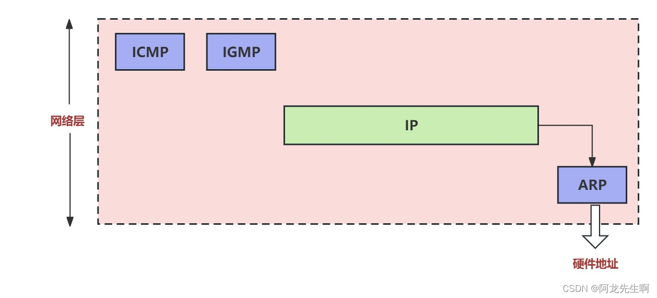
ARP (Address Resolution Protocol) is the Address Resolution Protocol . Since the IP protocol uses the ARP protocol, the ARP protocol is usually classified as a network layer. The purpose of the ARP protocol is to resolve the hardware address used at the data link layer from the IP address used at the network layer.
Address Resolution Protocol ARP stores a mapping table from IP addresses to hardware addresses in the host ARP cache, and this mapping table is often dynamically updated (added or deleted over time). Each host is equipped with an ARP cache (ARP cache), which contains a mapping table from the IP address of each host and router on the local area network to the hardware address. These are some of the addresses currently known to the host. So how does the host know these addresses? We can illustrate with the following example.
3.2 ARP workflow
When host A wants to send an IP datagram to a certain host B on the local area network, it first checks whether there is the IP address of host B in its ARP cache. If so, find its corresponding hardware address in the ARP cache, write this hardware address into the MAC frame, and then send the MAC frame to this hardware address through the LAN. It is also possible that the IP address of host B cannot be found. This may be because host B has just connected to the network, or it may be that host A has just been powered on and its cache is still empty. In this case, host A automatically runs ARP, and then follows the following steps to find out the hardware address of host B.
(1) The ARP process broadcasts an ARP request packet on the local area network . The following figure (a) is a schematic diagram of host A broadcasting and sending ARP request packets. The main content of the ARP request packet is: "My IP address is 209.0.0.5 and the hardware address is 00-00-C0-15-AD-18. I want to know the hardware address of the host with IP address 209.0.0.6."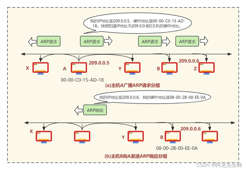
(2) The ARP processes running on all hosts on this LAN receive this ARP request packet.
(3) The IP address of host B is consistent with the IP address to be queried in the ARP request packet, so it accepts the ARP request packet, sends an ARP response packet to host A, and writes its own hardware address in the ARP response packet. . Since the IP addresses of all other hosts are inconsistent with the IP addresses to be queried in the ARP request group, they ignore this ARP request group, as shown in (b) above. The main content of the ARP response packet is: " My IP address is 209.0.0.6, and my hardware address is 08-00-2B-00-EE-0A. " Please note: Although the ARP request packet is sent by broadcast, the ARP The response packet is an ordinary unicast, that is, sent from a source address to a destination address.
(4) After host A receives the ARP response packet from host B, it writes the mapping from host B's IP address to the hardware address in its ARP cache.
When host A sends a datagram to B, it is very likely that host B will send a datagram to A soon, so host B may also send an ARP request packet to A. In order to reduce the traffic on the network, when host A sends its ARP request packet, it writes the mapping of its IP address to the hardware address into the ARP request packet. When host B receives the ARP request packet from A, it writes the address mapping of host A into host B's own ARP cache. It will be very convenient for host B to send datagrams to A in the future.
ARP sets a survival time (for example, 10 to 20 minutes) for each mapped address item stored in the cache. All items that exceed the survival time are deleted from the cache, and the cached hardware device addresses that have expired are cleared in a timely manner.
3.3 Four typical situations of ARP
ARP solves the mapping problem between the IP address and the hardware address of the host or router on the same LAN. The resolution from the IP address to the hardware address is performed automatically, and the user of the host is unaware of this address resolution process. As long as a host or router wants to communicate with another host or router with a known IP address on the network, the ARP protocol will automatically resolve this IP address into the hardware address required by the link layer.
Below we summarize four typical situations in which ARP is used.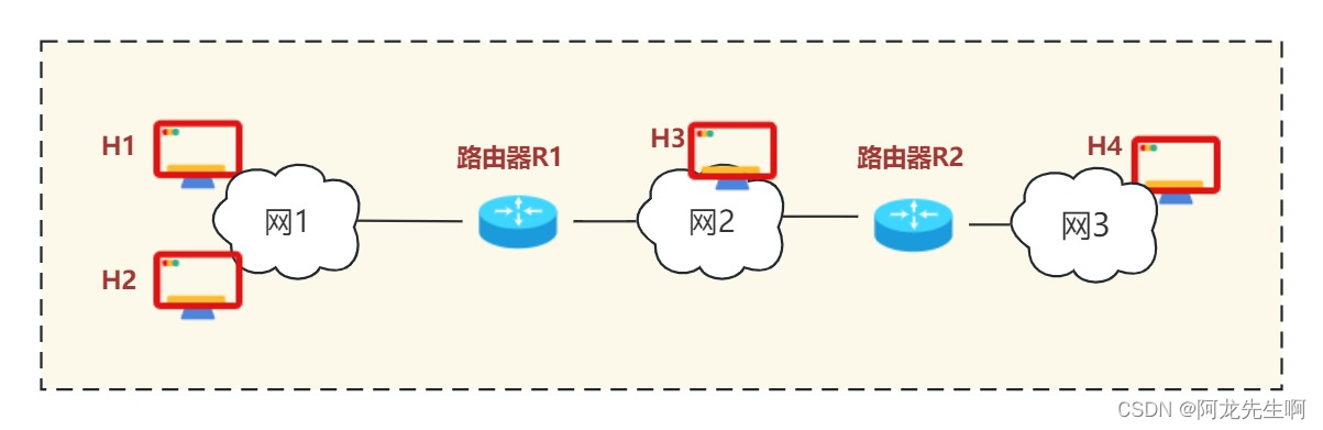
(1) The sender is a host (such as H1) and wants to send the IP datagram to another host on the same network (such as H2). At this time, H1 sends an ARP request packet (broadcast on network 1) to find the hardware address of the destination host H2.
(2) The sender is a host (such as H1) and wants to send the IP datagram to a host on another network (such as H3 or H4). At this time, H1 sends an ARP request packet (broadcast on network 1) to find the hardware address of a router R1 on network 1. Router R1 does the rest. What R1 needs to do is (3) or (4) below.
(3) The sender is a router (such as R1) , which wants to forward the IP datagram to the host (such as H3) connected to the same network (Network 2) as R1. At this time, R1 sends an ARP request packet (broadcast on network 2) to find the hardware address of the destination host H3.
(4) The sender is a router (such as R1) , which wants to forward the IP datagram to a host on network 3 (such as H4). H4 and R1 are not connected to the same network. At this time, R1 sends an ARP request packet (broadcast on network 2) to find the hardware address of a router R2 connected to network 2. The rest of the work is done by this router R2.
There are many situations where ARP needs to be used multiple times. But this is just the repeated use of the above situations.
The following figure shows the window system using the arp -a command to view the local ARP cache table:

4. Forwarding process of IP protocol
As shown in the figure below, computer A sends data to computer B through multiple networks. What is the data transmission process?

There are many choices for the transmission path for computer A to send data to computer B. For the time being, we randomly select a transmission path and straighten it as shown below.

The data goes through network 1 to the router, through network 2 to the router, and through network 3 to computer B. This transmission method is called hop-by-hop. In abstract terms, the transmission of data in the network jumps from one IP address to another.
Computers and routers all have a routing table, which stores paths to specific network addresses.
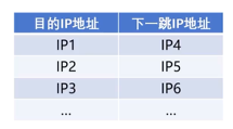
Assume that the above figure is the routing table of computer A. The data wants to reach the destination address IP1, and the IP address of the next hop is IP4; the data wants to reach the destination address IP2, and the IP address of the next hop is IP5.

Analyzing only from the network layer, the process of A sending data to B is as follows:
- A sends an IP datagram with destination IP B, and queries its own routing table and finds that the next hop is E.
- A sends the datagram to E.
- E queries the routing table and finds that the next hop is F, and sends the datagram to F.
- F queries the routing table and finds that it is directly connected to the destination IP device B, and sends the datagram to B.
Combine the network layer and data link layer to analyze the data forwarding process, as follows:
- A sends an IP datagram with destination IP B, queries the routing table and finds that the next hop is E; A hands the IP datagram to the data link layer and informs the destination MAC address is E; the data link layer fills in the source MAC address A and destination MAC address E; the data link layer sends the data to E through the physical layer.
- E's data link layer receives the data frame and hands the frame data to the network layer; E queries the routing table and finds that the next hop is F; E's network layer then hands the datagram to the data link layer and informs the destination MAC The data link layer with address F; E encapsulates the data frame and sends it.
- F's data link layer receives the data frame and hands the frame data to the network layer; F queries the routing table and finds that the next hop is B; F's network layer then hands the datagram to the data link layer and informs the destination MAC The address is B; the data link layer of F encapsulates the data frame and sends it.
During the data forwarding process, the MAC address of each hop of the data frame changes, while the IP address of each hop of the IP datagram remains unchanged.