=
1. Introduction to data sources
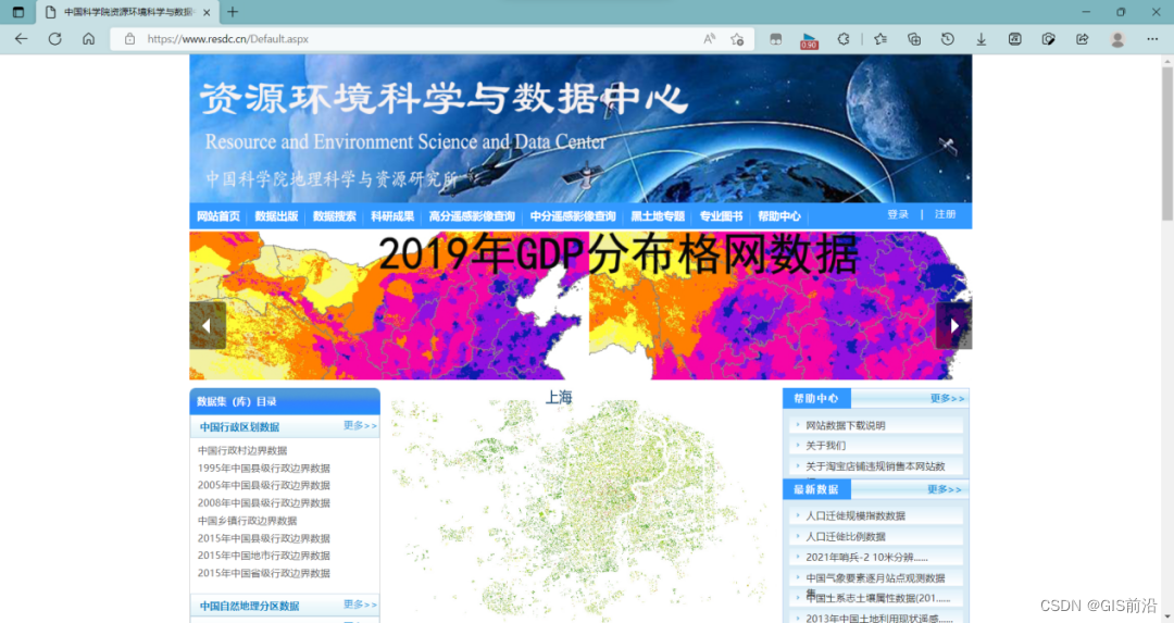
- digital elevation data
Digital elevation data comes from the Resource and Environmental Science and Data Center of the Chinese Academy of Sciences (https://www.resdc.cn/Default.aspx).
- Gongzhuling City remote sensing image data
Remote sensing image data data source network.
There is a data download link at the end of the article
2. Data preprocessing
- Gongzhuling City remote sensing image data preprocessing
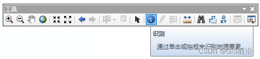
As can be observed from the previous picture, the remote sensing images downloaded from the software have white edges, which requires us to process the white edges first before proceeding.
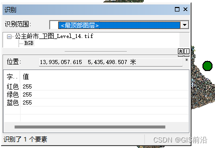
Before using the copy raster tool to process the image, we first need to know what the background value (white edge) is. The white edge is generally 255, and the black edge is generally -999. To ensure correctness, you can use the identification tool to detect it.
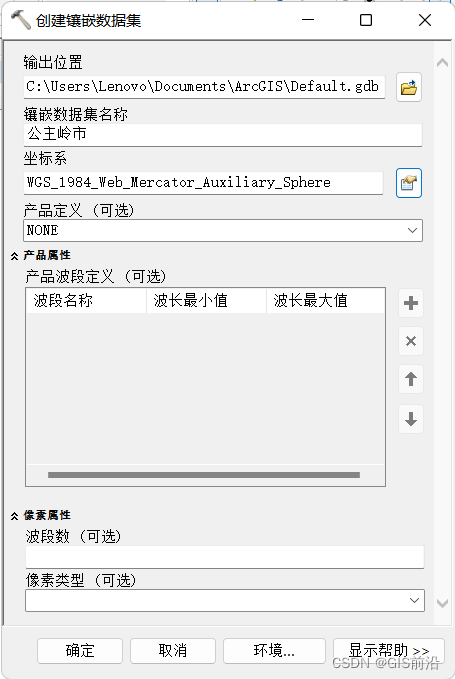
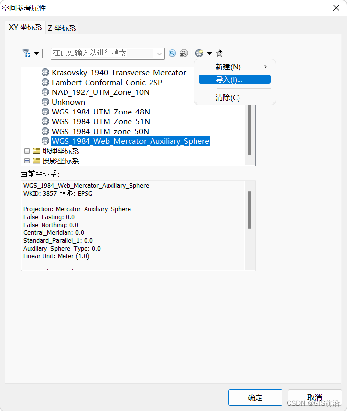
Create a mosaic dataset in a geodatabase. Here we create it in the default file geodatabase, and the coordinate system can be added by importing (importing the coordinate system of remote sensing images).
Tool location: Data Management Tools->Raster->Mosaic Dataset->Create Mosaic Dataset
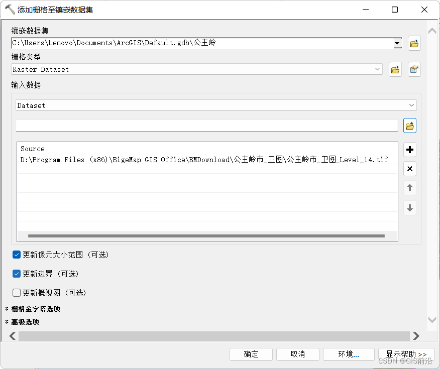
Use the [Add Data to Mosaic Dataset] tool to add remote sensing images to the mosaic dataset.
Tool location: Data Management Tools->Raster->Mosaic Dataset->Add Data to Mosaic Dataset
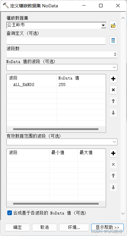
After that, you can use the [Define Mosaic Dataset Nodata] tool in the mosaic dataset to define the invalid values of the data. Select ALL_BANS for the NoData value band, set the NoData value to 255 (the value of the white edge previously detected with the identification tool), check [Synthesize NoData values based on each band], the remote sensing image has 3 bands, after selecting only these three The pixel will become NoData only when the values of each band are 255. Otherwise, as long as one band in the pixel has a value of 255, it will be set to NoData.
Tool location: Data Management Tools->Raster->Mosaic Dataset->Define Mosaic Dataset Nodata
The mosaic dataset itself also supports raster functions. Similar to the function template settings in the image data window, function chains can also be set to implement some complex requirements.
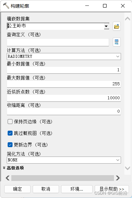
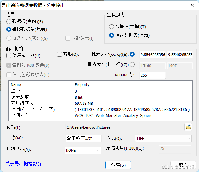
Of course, when we use a mosaic dataset, we can also remove invalid values when constructing the outline. But its removal is not perfect. There will be some white pixels around the image. The number depends on the approximate number of vertices. The greater the number of approximate vertices, the closer the contour fits the image, and the better the white edges are removed. Here we set 10,000 (the largest).
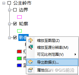
Right-click the image, select [Export Data], and set the range to the mosaic dataset.
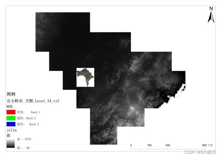
2. Digital elevation data preprocessing
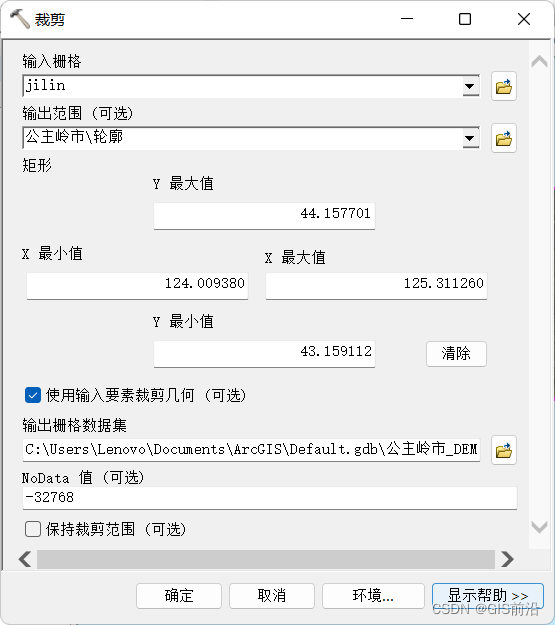
Use the cropping tool to crop digital elevation data.
Tool location: Data Management Tools->Raster->Raster Processing->Crop
3. ArcScene
- 3D surface
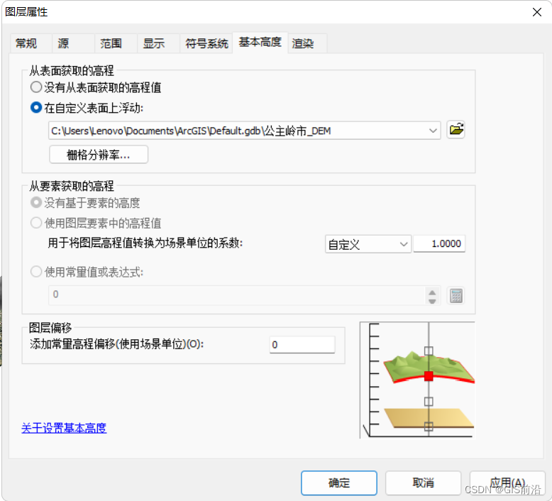
Add remote sensing images with white edges removed and cropped digital elevation data of Gongzhuling City, right-click the image layer, select Properties -> Basic Height, and select [Float on custom surface] for [Elevation Obtained from Surface], where the default setting is Digital elevation data added together.
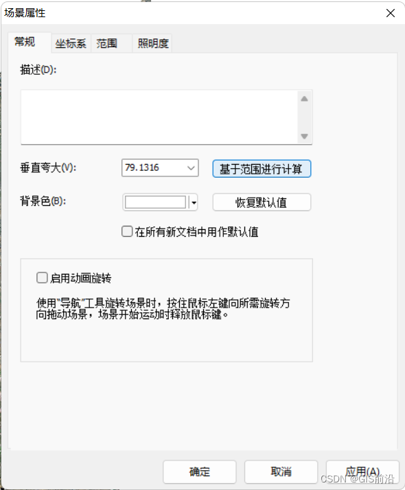
Right-click the data frame, select Scene Properties -> General, and click Calculate based on range.
- side section
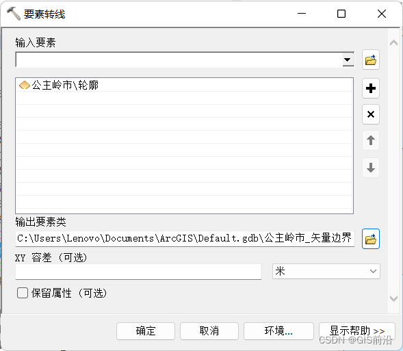
Use the Feature to Line tool to export the outlines in the mosaic dataset as a vector layer.
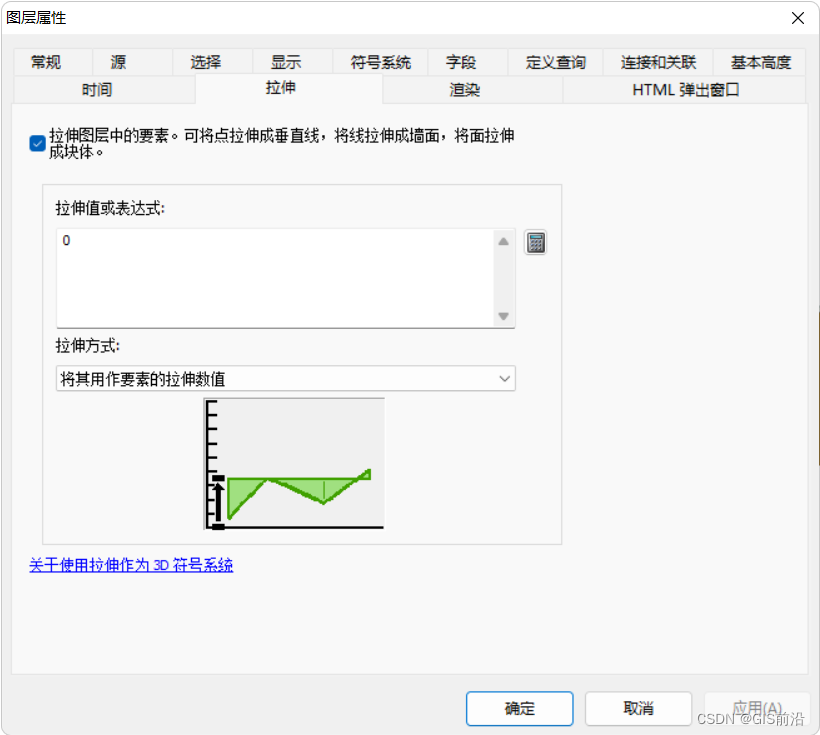
Add a vector boundary to ArcSence, right-click the layer, set the same basic height, switch the Stretch tab, and check [Stretch features in the layer]. You can use...Bara...] and select the stretching method as [Use it as the stretch value of the element].
- Change display settings
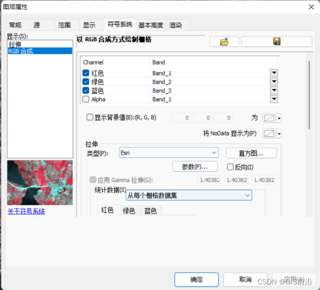
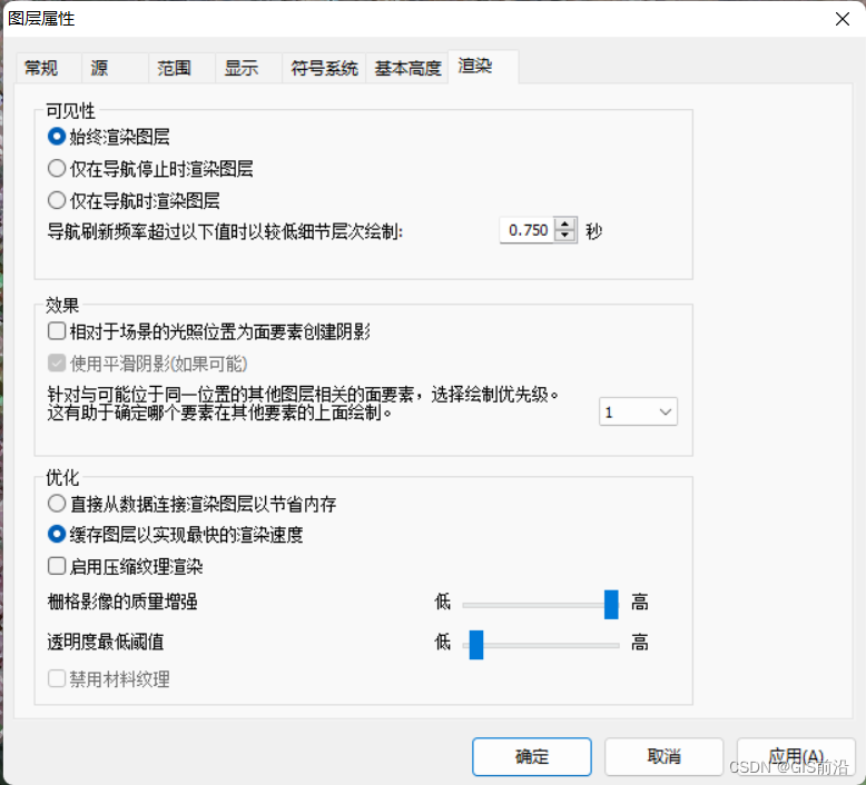
Right-click the image layer, select Properties -> Symbology, change the type under Stretch to Esri, switch the Rendering tab, and pull [Raster Image Quality Management] to the highest level, which can make the image more realistic.
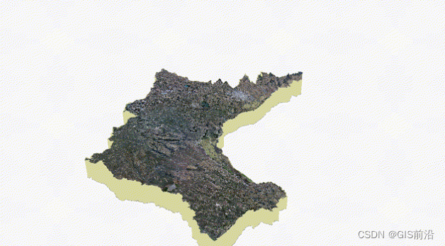
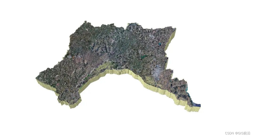
4. Results display