Table of contents
1.2, Repeater (physical layer)
1.4, Network bridge (data link layer)
2. Working behavior of the switch
4. Switch link type and VLAN division
5. vlan-access&trunk experiment
5.2, realize that under different switches, PCs under the same vlan can communicate
6. vlan-access&trunk experiment
7. Single-arm routing experiment
8. Layer 3 switches achieve single-arm routing effect
1. The evolution of switches
1.1, Minimum network unit
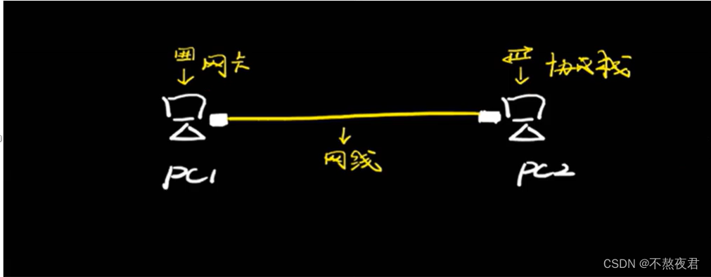
The minimum network unit consists of the following three parts:
Network Card: Converts our information into electrical signals
Network cable: used as a transmission medium to transmit electrical signals
Protocol stack: similar to the language used to communicate between two hosts. For example, two hosts must support the tcp/ip protocol stack to communicate accordingly.
Disadvantages: 1. The transmission distance of the network cable is short. If it exceeds one hundred meters, packet loss (data loss) will begin. 2. If multiple hosts need to communicate, this connection structure is obviously too troublesome.
1.2, Repeater (physical layer)

As shown above:
We add a signal amplifier (repeater) between the network cables to amplify the signal, which can extend the transmission distance of information on the network cable.
Disadvantages: Because the repeater only has two ports, communication between three hosts is not possible.
1.3, hub (physical layer)

As shown above:
There are multiple ports on the hub for connection, which solves the problem of few repeater ports.
Working mode: When an interface receives data, the hub will copy the data and send it to other interfaces (excluding the interface that received the data). This working mode is called flooding .
Disadvantages: All interfaces on a hub form a conflict domain. If pc1 sends data, after receiving the data on the hub, it will also send the data to other interfaces. At this time, pc2 and pc3 in the above picture are both Data cannot be sent. But in this case, the utilization rate of our transmission medium will be reduced.
Supplement: This protocol to prevent data transmission collisions is called CSMA/CD: Carrier Sense Multiple Access Protocol with Collision Detection.
1.4, Network bridge (data link layer)

As shown above:
Introduction to working principle:
Caching: The bridge will first cache and process the received data frames.
Filtering: By querying the mac address table, determine whether the target node of the incoming frame is located in the network segment that sent the frame (in the same port). If so, the bridge will not forward the frame to other ports of the bridge. (There is a mac address table in the bridge device, which records the mac address of the host connected to each port of the bridge)
Forwarding: After querying the mac address table, it is found that the target node of the frame is located on another network, and the bridge sends the frame to the correct network segment (forwarding to another port)
Disadvantages: A bridge has only two ports, so to connect multiple devices first, you still need to add a hub to connect. However, if you add a hub, you will return to the old problem of conflict domains. So in general: the disadvantage of the network bridge is that although the area is separated, it seems as if it is not divided.
1.5, switch
The switch adds more ports on the basis of the bridge, so that multiple hosts can be connected without a hub and the forwarding speed is faster.
2. Working behavior of the switch
2.1, behavior
1. Learning: Record the source MAC and incoming interface information of the data frame
2.
If the forwarding is a unicast data frame, check the MAC address table according to the destination MAC to see if there is a mapping relationship
> 1. If there is a mapping relationship, the "known unicast data frame" directly follows the mapping relationship in the MAC address table Forwarding
> 2. If there is no mapping relationship, "unknown unicast data frame" performs flooding action: xxxxx
If it is a broadcast data frame/multicast data frame
> 1. Flooding: from other than the receiving port All ports copy and send a copy of
3, discard: If the switch interface receives a certain data frame and finds that it needs to be forwarded from the receiving port, it will be discarded.
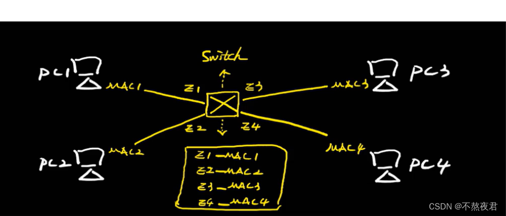
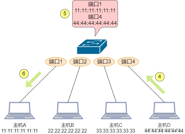
4. Now let’s simulate a scenario to see how the switch learns the mac address.
Host A sends data to host D: A sends a data frame. The source MAC address of the data frame is 11:11:11:11:11:11, and the destination MAC address is 44:44:44:44:44:44. Switch port 1 receives the data frame and records the source MAC address and the port's corresponding MAC address table entry . The switch does not know which port the destination MAC address is on, so it floods the data frame, that is, it forwards it to all ports except port 1. B and C find that the destination MAC address is not their own and will discard the data frame.

D finds that the data frame is sent to itself, so it sends a response data frame. The source MAC address is 44:44:44:44:44:44, and the destination MAC address is 11:11:11:11:11:11. Switch port 4 receives the data frame and records D's MAC address entry . So the switch knows the MAC address information of host A and host D, and then forwards according to the MAC address table. The switch can learn the MAC addresses of host B and host C in the same way.
2.2, summary
1. Learning: Learn the source MAC and the incoming interface to build a MAC address table [CAM]
B=Broadcast M=Multicast U=unknown unknown unicast frame
2. Forwarding: For BUM data frames, perform flooding behavior, for known unicast frames Broadcast data frames and perform table lookup for forwarding behavior.
3. Discard: After receiving the data, the data needs to be sent from the interface, and it will be discarded at this time.
Learning: Packet learning = dynamic MAC address table Static MAC address table = artificially configured MAC address table information
MAC address table existence time = 300S Aging time = 5M
Five minutes If there is no data information about the MAC, the MAC corresponding to this time MAC address table entries will age naturally.
Unexpected: After the physical interface associated with the MAC address table fails, all dynamic MAC address information associated with the interface will be deleted.
Features: One interface of the switch can correspond to multiple different MAC addresses at the same time; for the same MAC address, the switch will only have one corresponding interface.
3. VLAN
3.1, Introduction to VLAN
Definition:
VLAN (Virtual Local Area Network) is a communication technology that logically divides a physical LAN into multiple broadcast domains. Hosts within a VLAN can communicate directly with each other, but cannot communicate directly with each other, thus limiting broadcast packets to one VLAN.
Purpose:
Ethernet is a data network communication technology based on CSMA/CD (Carrier Sense Multiple Access/Collision Detection) shared communication medium. When the number of hosts is large, problems such as serious conflicts, flooding of broadcasts, significant performance degradation, and even network unavailability may occur. Although LAN interconnection through switches can solve the problem of serious conflicts, it still cannot isolate broadcast packets and improve network quality.
In this case, VLAN technology emerged. This technology can divide a LAN into multiple logical VLANs. Each VLAN is a broadcast domain. The communication between hosts in a VLAN is the same as within a LAN, and the communication between VLANs is Otherwise, they cannot directly communicate with each other. In this way, broadcast packets are limited to one VLAN.
3.2. Basic concepts of VLAN
VLAN tag:
To enable the device to distinguish packets of different VLANs, a field identifying VLAN information needs to be added to the packet. The IEEE 802.1Q protocol stipulates that a 4-byte VLAN tag (also called VLAN Tag, or Tag for short) be added after the destination MAC address and source MAC address fields and before the protocol type field of the Ethernet data frame to identify VLAN information.
VLAN frame format:

This is reflected in the packets. This is a packet captured under the trunk port (it cannot be captured on ordinary ports because the access port will strip off the tag, and untagged hybrid cannot be captured. You can also capture it on tagged hybrid. Because he doesn’t peel off tags either) :

TPID: Tag protocol ID: 802.1Q=0x8100 =Public 802.1Q 2B
pri: Priority 3bit 2^3=8 represents the priority of vlan data==QOS-Quality of Service
CFI: The first 1bit is 0=Ethernet Data frame = classic format, 1 = non-Ethernet data frame is not classic. By
default, all interfaces of the switch belong to VLAN-1 .
Vlan-id: VLAN number 12bit 2^12=4,096. All VLAN-ID numbers are 0-4095, but 0 and 4095 are reserved, so 1-4094 can be used (this will be reflected in our experiments)
TCI: tag control information:
After tag control information divides the interface into a VLAN, each interface will have its own link type. At this time, different link types have different processing behaviors for data.
Default VLAN:
The default VLAN is also called PVID (Port Default VLAN ID). As mentioned earlier, the data frames processed by the device are all tagged. When the device receives an untagged frame, it needs to add a tag to the frame. What tag to add is determined by the default VLAN on the interface.
The process of adding or removing tags when the interface sends and receives data frames.
For the Access interface, the default VLAN is the VLAN it allows to pass through. Modifying the default VLAN can change the VLAN that the interface allows to pass through.
For Trunk interfaces and Hybrid interfaces, one interface can allow multiple VLANs to pass through, but it can only have one default VLAN. The default VLAN and allowed VLAN of the interface need to be configured separately and do not affect each other .
Other knowledge points:
PVID===port vlan-id: VLAN-ID number
of the interface For flooding on the switch: Flooding will be carried out to other ports that can forward this VLAN except the receiving port.
1. The TAG will not be stripped in the receiving direction.
2. The switch internally processes data frames with TAG.
4. Switch link type and VLAN division
4.1, Switch link type (please read it carefully, it will be of great help to the understanding of the following experiments)
1. Access (access type) features: It can only belong to a certain VLAN. At this time, only one VLAN can be tagged/stripped. Used for: connecting terminal equipment PC/printer/camera/router/
Receiving direction:
- If a blank data frame is received, the PVID of the interface is marked and processed inside the switch.
- If a data frame carrying a tag is received, first check whether the VLAN-ID of the data is consistent with the PVID of the interface. If they are consistent, the frame will be received normally and processed inside the switch. If it is inconsistent, it will be discarded directly.
Shipping direction:
- When sending data, the VLAN-ID number that is the same as the PVID is stripped off.
2. Trunk (trunk type) features: allowing multiple different VLANs to pass through at the same time. List: Allowed list of VLAN // The prerequisite for passing is to ensure that the VLAN exists. Function: The link connecting switches to switches.
Acceptance direction:
First possibility:
- If a blank data frame is received, first add the PVID of the interface, and then proceed to the next step.
- Check the VLAN allowed list. If it does not exist, it will be discarded. If it exists, it will be received. The data will be processed inside the switch.
Second possibility:
- If a data frame carrying a tag is received, directly check the VLAN allowed list. If it does not exist, it will be discarded. If it exists, it will be
received and the data will be processed inside the switch.
Shipping direction:
- Check whether the VLAN where the data exists is in the VLAN allowed list of the interface. If it does not exist, discard it. If it exists,
proceed to the next step. - At this time, the VLAN-ID number in the data will be compared with the PVID of the interface, and different processing actions will be performed based on different results. If they are the same: the VLAN will be stripped and sent; if they are different: the data will not be modified in any way.
3. Hybrid (hybrid port) features: capable of stripping labels for multiple different VLANs in the sending direction at the same time
Acceptance direction:
First possibility:
- If a blank data frame is received, first add the PVID of the interface, and then proceed to the next step.
- Check the VLAN allowed list. If it does not exist, it will be discarded. If it exists, it will be received. The data will be processed inside the switch.
Second possibility:
- If a data frame carrying a tag is received, directly check the VLAN allowed list. If it does not exist, it will be discarded. If it exists, it will be
received and the data will be processed inside the switch.
Shipping direction:
- Check whether the VLAN where the data exists is in the VLAN allowed list of the interface. If it does not exist, discard it. If it exists,
proceed to the next step. - Hybrid defines multiple VLANs to pass through with or without tags based on the sending direction of the interface.
If it is tagged mode, it is sent with the VLAN-tag. ===Trunk/Multiple vlans pass
If it is in untagged mode, the VLAN-tag is stripped and sent. ==Access/Superimposed Access ()
4. Supplementary
4.1. After the interface is configured with PVID, if the VLAN is not untagged or tagged under the Hybrid interface, the VLAN will not be in the vlan allowed list.
4.2. If the PVID is modified on the switch and the PVID numbers at both ends are inconsistent, the same VLAN may not be able to communicate, but different VLANs can communicate, so usually the PVID of the interface will not be modified.
4.3, regardless of Access/Trunk: labels can be stripped for up to 1 vlan at the same time.
4.4, the trunk interface will strip the label only when the VLAN-ID is equal to the PVID.
5. vlan-access&trunk experiment
The network topology diagram is as follows,
Topology diagram 1

Experimental requirements:
1. Using vlan technology, pc3 can communicate with pc7 but cannot communicate with pc4.
2. PCs under the same vlan can communicate under different switches. For example, pc3 in the picture above can communicate with pc5.
3. The specific information has been marked in the topology diagram.
5.1, realize the configuration of communication between the same vlan and isolation between different vlans under a switch.
First, implement the configuration of communication between the same vlan and isolation between different vlans under a switch.
Configuration of pc: The configuration of pc7 is as follows. There is no gateway configured here because this experiment does not involve layer three.

Make the following configuration in SW2
1. Enter system view
2. Modify the device name (in order to distinguish the device, I changed it to SW2 here)
3. Create the required vlan. We need vlan 10 and vlan 20 here (command: vlan batch 10 20)
4. Enter the interface and configure the link type for the interface. The interface types used by g0/0/2 and g0/0/1 here are access (command: port link-type access can be abbreviated as pla, as shown below)
5. Then, configure the corresponding vlan for the interface. The vlan used by g0/0/2 here is 20 (command: port defualt vlan 20, abbreviated as: pdv 20),

After performing the above operations, we have completed the operation of the g0/0/2 interface of SW2. So for the g0/0/1 and g0/0/4 interfaces, we can do the same thing, but if we want pc3 to be able to communicate with pc7 but not pc4, then we need to configure g0/0/4 as vlan10, Just configure g0/0/1 as vlan20.
Then, we use pc3 to ping pc4 and pc7 to test it. We found that the requirements were met.

5.2, realize that under different switches, PCs under the same vlan can communicate
Now let's implement the requirement that PCs under the same vlan can communicate under different switches.
I will not show the configuration of interfaces g0/0/1 and g0/0/2 of SW3 here. The above are all configurations of access ports.
Now show the configuration of the SW3 interface g0/0/3 interface. Note that here we need to configure the interface as a trunk port.
The configuration is as follows:
1. Port link-type trunk is abbreviated as plt.
2. Port trunk allow-pass vlan all means that all vlan packets are allowed to pass, including vlan10 and 20. Here we can also write port trunk allow-pass vlan 20 10, which means that only vlan10 and 20 packets are allowed to pass.
3. At the same time, please note that we also need to configure the following configuration on the opposite end, that is, the g0/0/3 interface of SW2, which is also a trunk port.

After completing the configuration, we use pc3 to ping pc5 and we will find that the ping is successful. Then the experiment was successful.
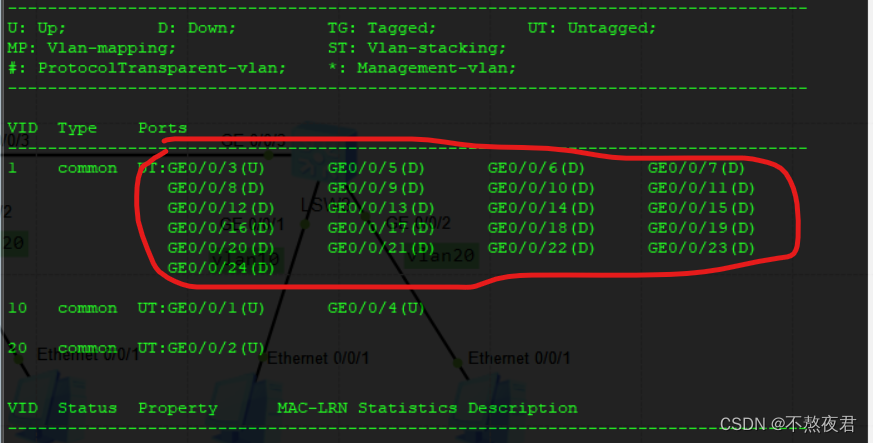
Supplement: In fact, all interfaces of our switch belong to vlan 1 by default at the beginning, as shown below:
5.3, remaining issues
5.3.1. Why are g0/0/1, 2, and 4 under SW2 access ports?
First of all, we already know the working principle of the access port. When the switch receives the data from pc3 to pc7, the switch will first check whether the data contains vlan-id. If it contains vlan-id, it will check whether the vlan-id is consistent with the vlan-id. The pvid of this interface is consistent (we can use the display vlan command to view the pvid of the interface, as shown in the figure below. We find that the pvid of the interface is consistent with our configured vlan, which is a feature of the access interface). If they are consistent, the data enters the switch. deal with. If it is inconsistent, then it will discard the data. If there is no vlan-id, then it will be marked with the pvid specified by the current interface. Therefore, the pc3 data received by the switch is now marked with the pvid of vlan 10, and then sent to the same pvid. Interface g0/0/4, then peel off the pvid and send it to pc7.

5.3.2. Why are g0/0/3 of SW2 and g0/0/3 of SW3 both trunk ports?
Now that we know the working principle of the trunk port, we can speculate on the process of pc3 pinging pc5. First, pc3 sends the data frame without written vlan id to the switch. At this time, the switch marks the pvid of the interface on the data frame. Then, the switch checks Check whether this pvid can pass through this trunk port. Because we configured port trunk allow-pass vlan all, it can pass. When it comes to the g0/0/3 interface of SW3, since the interface configuration is also port trunk allow-pass vlan all, So SW3 receives the data, and then follows the old routine, removing the tag from the g0/0/1 interface and sending it to pc5.
We can look at packets with and without tags.
6. vlan-Hybrid experiment
Topology diagram 2

Experimental requirements:
1. The VLAN division is as shown in the figure above.
2. PC8 can access pc10, but pc8 cannot access pc9.
6.1, SW4 configuration
First let’s configure SW4
1. Enter system view
2. Modify the device name (in order to distinguish the device, I changed it to SW4 here)
3. Create the required vlan. We need vlan 2, 3, 100 here (command: vlan batch 2 3 100)
4. Enter the interface and configure the link type for the interface. Here, the interface types used by g0/0/3, g0/0/2 and g0/0/1 are all hybrid (command: port link-type hybrid can be abbreviated as pla, as shown below)
5. Enter the interface to configure the pvid of the interface. Be sure to remember to configure it (I did not configure it at the time, so I made an error). This step is not available when configuring the access interface, because an access interface only belongs to one vlan, so the pvid of the interface is equal to vlan id
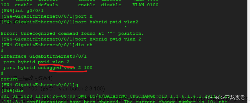
6. Configure the vlan of the interface and how to process the received vlan.

The configuration of g0/0/1 is the same as above. I won’t show it because only the passed vlan needs to be changed. Since the data of vlan 2 cannot be passed but the data of vlan100 must be passed, it is port hybrid untagged vlan 2 100.
The configuration of g0/0/3 is as follows: Note that there is no need to configure pvid here, because I do not have vlan configured here! (That is, between SW4 and SW5)

Finally, we tested it with pc8 again. We found that the configuration met the requirements and the experiment was successful.

7. Single-arm routing experiment
Topology diagram one

Experimental requirements: pc11 and pc12 are now on different network segments and different vlans, and they need to communicate with each other.
7.1, configuration details
First of all, we know that when hosts need to communicate across network segments, we need a gateway to help us look up tables and forward. When we do not have a three-layer switch, we must use a router to implement this requirement. The router has one Technology - Virtual subinterface (subinterface) applied to single-arm routing.
First, we configure the switch. The configuration requirements are as follows: I will not show the configuration details here. The configuration of the access port and trunk port has been discussed above.

Here we mainly configure the router. The configuration of the router is as follows:
1. Enter the system view.
2. Create a sub-interface. Note: The way to create a sub-interface on Huawei equipment is int original interface. sub-interface serial number. As follows: I created int g0/0/0.1
3. Configure IP on the sub-interface as the gateway IP. The g0/0/0.1 subinterface here is used as the gateway of pc11, so the configured IP is 192.168.1.1
4. Configure the vlan number that is allowed to communicate on this sub-interface. dot1q termination vid 10 means that packet communication of vlan 10 is allowed. Note that it is dot1q instead of dotlq.
5. Finally, we need to enable the function of forwarding arp messages on the interface. This function needs to be manually enabled on Huawei equipment, but it is enabled by default on Cisco equipment. (We will talk about why we need to turn it on later)
6. We create int g0/0/0.2 and perform the above operations, except that our gateway needs to be changed to 192.168.2.1. (We have already configured the gateway on the computer before, so we can configure it directly)

After that, we use pc11 to ping pc12 to test it. As follows: The phenomenon meets the requirements and the experiment is successful!

7.2, Thinking
Why does the router need to enable the arp forwarding function?
First, let’s capture the packet at the following location and use pc11 to ping pc12

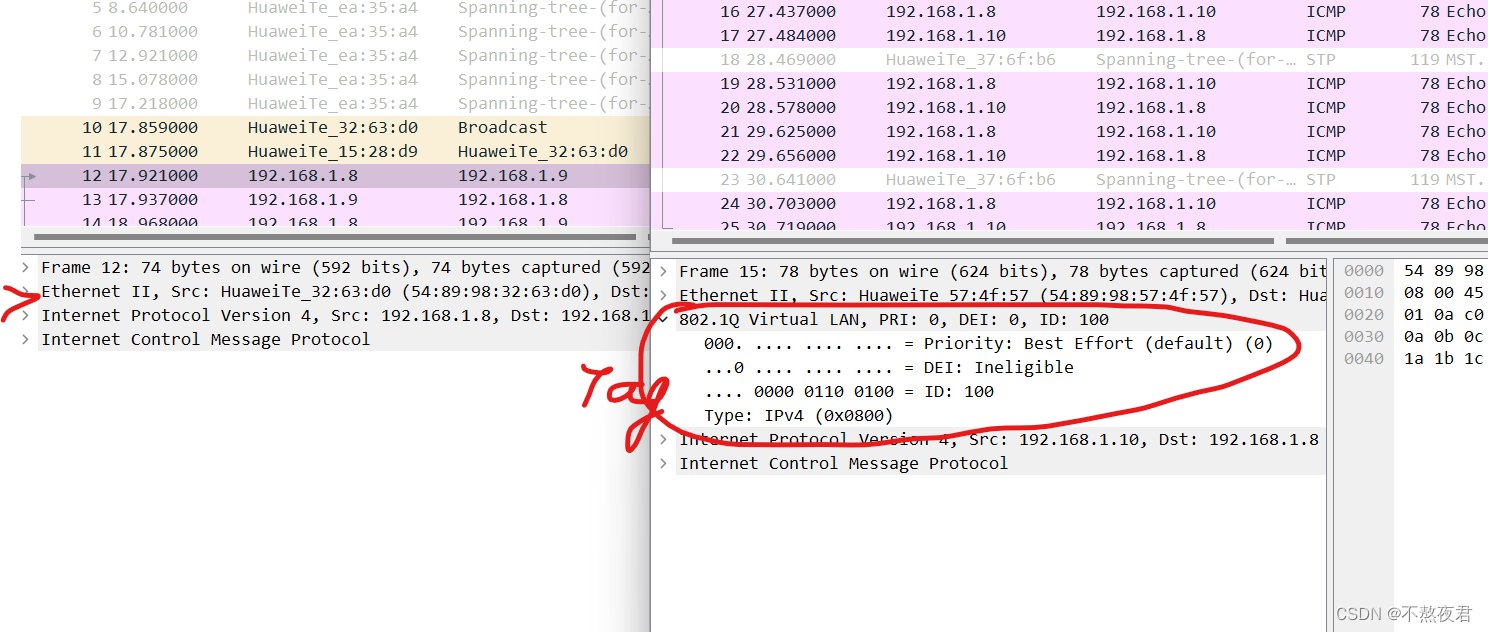
The packets we captured on the g0/0/0 interface are as follows:

From the packages we captured, we can know the following process:
1. Since pc11 does not have the mac address of the gateway, pc11 sends an arp broadcast to ask who is 192.168.1.1
2. After the router receives the arp broadcast packet, it fills in the mac address of the router's int g0/0/0 interface and sends it back in unicast form, as follows:

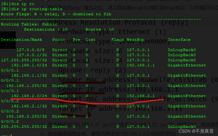
3. When the router receives the message from 192.168.1.11 (pc11) requesting 192.168.2.12 (pc12), the router queries the arp table and finds that there is no mac address for 192.168.2.12. Go to the next step.
4. The router queries the routing table to see if there is a route to the 192.168.2.0/24 network segment. If there is, the router will send a broadcast arp to ask for the mac address of 192.168.2.12. If there is no route, no operation will be performed. As shown in the following table:
We can know the route to the 192.168.2.0/24 network segment, so the router sends a broadcast arp to ask for the mac address of 192.168.2.12
5. After receiving the arp message asking for its own mac address, pc12 sends an arp unicast message filled with its own mac address to the router. At this point, the router has the mac addresses of pc11 and pc12.

6. After that, pc11 and pc12 can start communicating.
8. Layer 3 switches achieve single-arm routing effect
Topology diagram 2

Experimental requirements:
Use a three-layer switch to implement communication between hosts in different vlans and different network segments.
pc13: 192.168.1.13/24 Gateway: 192.168.1.1
pc14: 192.168.2.14/24 Gateway: 192.168.2.1
8.1, configuration details
1. Create the required vlan
2. Create a vlanif interface that handles the corresponding vlan as follows: Vlanif10
3. Configure the IP address of the vlanif interface
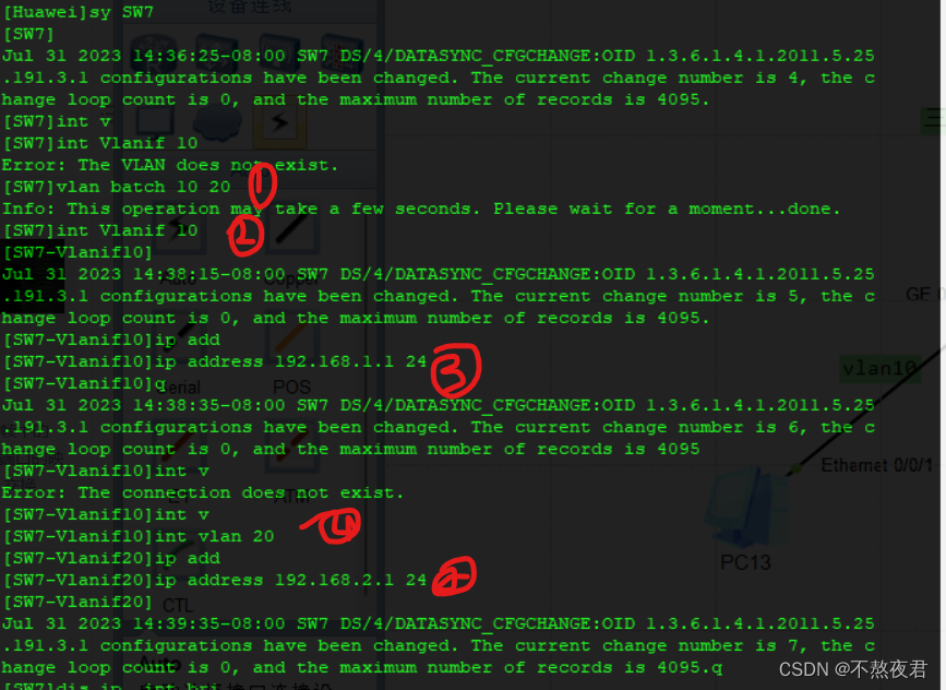
4. Configure the interface type for the switch interface, here is the access port
5. Configure vlan for the switch interface

6. Check the routing table of the switch to see if the configuration is successful. Yes, the Layer 3 switch has its own routing table.

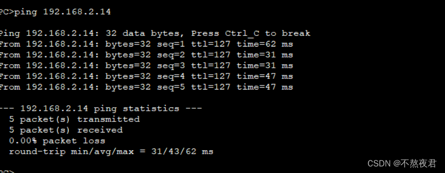
After completing the above configuration, we can test it. As follows, the experiment was successful
at last
That’s it for this blog’s introduction and experiments on switches, VLAN technology and experiments. If this blog is helpful to you, please like and collect it to support it. Thank you! promise me! Don't have sex for free, okay? Hahaha! See you in the next blog.