Table of contents
4. Experimental procedures and phenomena
Step1: Construct the experimental topology as follows
Step2: IP address configuration is as follows
Step3: Configure static routing
(2) NAT configuration-to achieve access to the public network
Step1: Construct the experimental topology as follows
(3) NAT configuration - intranet mapping
Step2: WEB server configuration
Step3: NAT port mapping configuration
I. Introduction
This series of articles will update the relevant experiments in the network system integration course. This article is the fourth article about the basic configuration of the router.
Other:
Parts 2 and 3 of this article are configured based on Experiment 3: Network System Integration Experiment (3) | System Integration Virtual LAN (VLAN) configuration .
emphasize:
For details on the original LAN configuration, see: Network System Integration Experiment (3) | System Integration Virtual LAN (VLAN) Configuration .
For details on the original LAN configuration, see: Network System Integration Experiment (3) | System Integration Virtual LAN (VLAN) Configuration .
For details on the original LAN configuration, see: Network System Integration Experiment (3) | System Integration Virtual LAN (VLAN) Configuration .
2. Experimental purpose
① Understand and master the basic configuration management of routers
② Master the relevant instructions for static routing configuration
③ Master NAT mapping related instructions and learn NAT for port mapping
3. Experimental requirements
① Conduct static routing experiments based on the original LAN
② Configure NAT experimental intranet equipment to access the public network
③ Configure NAT for port mapping to enable external network devices to access the external network WEB server
4. Experimental procedures and phenomena
(1) Static routing
Step1: Construct the experimental topology as follows

Step2: IP address configuration is as follows
PC1:

PC5 :

R2 :

R3 :
R4 :

Step3 : Configure static routing
R2 :
1.	#
2.	ip route-static 34.1.1.0 255.255.255.0 23.1.1.3
3.	ip route-static 45.1.1.0 255.255.255.0 23.1.1.3
4.	#
R3 :
1.	#
2.	ip route-static 12.1.1.0 255.255.255.0 23.1.1.2
3.	ip route-static 45.1.1.0 255.255.255.0 34.1.1.4
4.	#
R4 :
1.	#
2.	ip route-static 12.1.1.0 255.255.255.0 34.1.1.3
3.	ip route-static 23.1.1.0 255.255.255.0 34.1.1.3
4.	#
Step4 : Verification
① Verify whether static routing entries appear in the routing table of each router device
R2 :

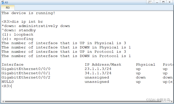
R3 :

R4 :

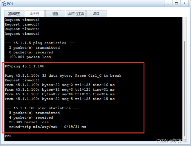
②Verify whether the PCs can communicate normally
(2) NAT configuration-to achieve access to the public network
Step1: Construct the experimental topology as follows
This experiment is configured based on the topology diagram of the previous experiment. The topology diagram is as follows:

Step2 : NAT configuration
Considering the complexity of NAT configuration, the Easy-ip configuration solution is adopted and the configuration on R1 is as follows:
1.	#
2.	acl number 2000
3.	 rule 5 permit source 192.168.0.0 0.0.255.255
4.	 rule 10 deny
5.	#
6.	#
7.	 nat alg dns enable
8.	 nat alg ftp enable
9.	 nat alg rtsp enable
10.	 nat alg sip enable
11.	 #
12.	 nat address-group 1 12.1.1.5 12.1.1.200
13.	#
14.	#
15.	interface GigabitEthernet0/0/0
16.	 ip address 12.1.1.2 255.255.255.0
17.	 nat outbound 2000 address-group 1
18.	#
19.	ip route-static 0.0.0.0 0.0.0.0 12.1.1.1
20.
Step3 : Effect verification
Test whether each internal network device can normally access the public network IP 12.1.1.1 . The results are as follows:
①Finance Department 1

②Finance Department 2

③Technical Department 1

④ Technical Department 2

The above experimental results show that the internal network device can already access the external network IP normally and the NAT configuration is correct.
(3) NAT configuration - intranet mapping
Step1: Add web server
Add a new server to the original topology dedicated to providing web services. The re-planned topology is as follows:

Step2: WEB server configuration
① IP address configuration

② WEB service configuration

Step3 : NAT port mapping configuration
Since port 80 of the server needs to be mapped to the external network to achieve external network conversion, the port mapping instructions in NAT need to be configured. Just execute the following instructions on R1:
1. nat server protocol tcp global 12.1.1.211 www inside 192.168.1.119 wwwStep4 : Effect verification
Since only opening port 80 cannot detect its connectivity through the ping command, you can only check the effect by viewing the corresponding instructions from the router. The instructions are as follows:

5. Two additional sentences
First of all, let me reiterate that the topology in the LAN in the second half of this experiment is based on the provisioning of Experiment 3. The link is as follows: Network System Integration Experiment (3) | System Integration Virtual LAN (VLAN) Configuration https://blog. csdn.net/as12138/article/details/129978438?spm=1001.2014.3001.5501 . If you want to configure according to this article, please be sure to provision it first . ![]()
Secondly, this article is for reference only. I hope you can configure your own configuration according to the article instead of directly copying the article and submitting it in your homework. Directly using other people’s homework results will not only fail to achieve the learning effect, but will also affect the actual results of yourself and others. It is disgraceful that the results will be affected. Thank you for your understanding.
Finally, thank you for reading this article carefully. If you think it is good, please give it a like . You are also welcome to communicate with me. Thank you for your support. It is a great honor.