Table of contents
(1) Congestion Control and Flow Control
2. Methods to solve congestion
(2) Deadlock and its prevention
1. Store-and-forward deadlock and its prevention
2. Reload deadlock and its prevention
2. Layer 3 switches and Layer 3 switching
(1) Three-layer switch hardware structure
1. Layer 3 switch with pure software routing module
2. Layer 3 switch with pure hardware routing module
3. Layer 3 switch combining software and hardware with routing module
(2) Three-layer switching principle
1. Network congestion control
Network congestion occurs when too many datagrams arrive at a certain part of a communication subnet and cannot be processed in time (the load on the subnet exceeds the throughput capacity of the network (number of packets/second)), causing problems in this part or even the entire network. Performance degradation phenomenon. When congestion is severe, network communication services may even come to a standstill, causing a deadlock.
In a network with congestion, datagrams arriving at a certain node will encounter the situation that no buffer is available and will be discarded, so that these datagrams have to be retransmitted by the source node, thus causing the communication subnet to The effective throughput decreases. This causes a loop, causing part or even all of the communication subnet to be in a deadlock state, eventually causing the effective throughput of the network to be close to zero.
(1) Congestion Control and Flow Control
Congestion control needs to ensure that the communication subnet can carry the traffic submitted by users. It is a global issue and involves the design of hosts, routers, and all factors related to reducing network transmission performance.
Flow control is related to point-to-point communication. It mainly solves the problem of fast senders and slow receivers. It is a local problem. The control method is to suppress the rate at which the sender sends data so that the receiver has time to receive or process it. Generally, it is Feedback-based control.
1. Main causes of congestion
There are three aspects: the node buffer capacity is too small, the communication bandwidth of the output link is not enough, and the processor speed is not fast enough.
2. Methods to solve congestion
There are 3 types:
1. Buffer preallocation method Buffer Preallocation
Commonly used in virtual circuit packet switching networks. When a virtual circuit is established, each node through which the call request packet passes is required to pre-allocate one or more data buffers for this virtual circuit (that is, each node must have a buffer for allocation). If a node currently does not have an available buffer (the response signal is "busy"), when establishing a virtual circuit, the call request packet is allowed to choose other paths to establish the virtual circuit. In this way, each node passing through the path can set up a permanent buffer for each virtual circuit (until the virtual circuit is removed), and there will always be space to receive and forward passing datagrams. When a node receives a datagram and forwards it, the node returns a confirmation message to the sending node (informing the sending node that it has been sent and can send another one). On the one hand, this confirmation message tells the receiving node that the datagram has been correctly received, and on the other hand, it tells the sending node that the node has vacated the buffer in preparation for receiving the next datagram.
If the protocol between nodes allows multiple unprocessed datagrams to exist, then in order to completely eliminate congestion, each node must reserve a window-sized number of buffers for each virtual circuit, regardless of whether there is actual traffic. In this way, a lot of resources will be occupied by a certain connection in the future, and the effective utilization of network resources will be low.
This congestion control method is mainly used in high-bandwidth, low-latency situations, such as digital voice.
2.Packet Dropping _
It is not necessary to reserve a buffer for datagrams in advance. Instead, subsequent datagrams are discarded when the router's buffer is full, and data packets are re-received only after the buffer frees up space.
If the network uses datagram service (no acknowledgment is required), using this method to prevent congestion will not have a big impact: because each packet of the datagram service has complete routing address information and can be selected independently Optimal routing, when it is found that the performance of the original path is poor, it will automatically switch to other better paths for packet exchange; furthermore, in the datagram service, the receiving node does not need to confirm after receiving the packet, so it can be done in a timely manner Even if it is discarded, it will not cause the sending node to wait for a long time for a confirmation response.
If the network uses virtual circuit services (requiring acknowledgment), a backup of the discarded datagram must be saved at a previous node so that it can be resent after the congestion is resolved.
3. Quota control method.
This is achieved by setting an appropriate number of special information called "licenses" in the communication subnet. Some of the licenses are pre-allocated to each source node with a certain strategy before the communication subnet starts working, and the other part is circulated around Wang Zhong after the subnet starts working. When the source node wants to send datagrams from the source system, it must first have a license and cancel a license for each datagram sent. The destination node generates a license each time it receives a datagram and submits it to the destination system. This ensures that the number of datagrams in the subnet does not exceed the number of licenses, preventing congestion from occurring. However, the transmission efficiency of the network may not be optimal.
This control method is somewhat like a medium contention solution on a Token Ring network. In a token ring network, the source node must obtain a unique token in the network to send data. The difference is that the certificate here is not unique, there can be many (the data is certain).
(2) Deadlock and its prevention
Deadlock means that some nodes are unable to receive and forward datagrams because they have no free buffers (a certain amount of buffer space is also required when forwarding). The result is that nodes wait for each other and cannot receive or forward datagrams. , and this deadlock has been maintained. In severe cases, it may even cause the entire network to be paralyzed.
Common deadlock situations and prevention methods
1. Store-and-forward deadlock and its prevention
The most common deadlock is a direct store-and-forward deadlock that occurs between two nodes. For example, the buffer areas at A\B\C are all full. A sends to B. When B is full, some packets must be sent out to free up space before sending; B sends to C, and C is also full; C sends to A. , A is also full. In this way, A waits for B to clear the buffer, B waits for C, and C waits for A. But in fact, under the current situation, the buffers of these three nodes cannot be cleared. When a node is in a deadlock state, all links connected to it will be completely congested.
solution:
1. Set m+1 buffers for each node and number them sequentially. m is the diameter of the communication subnet, that is, the maximum number of link segments from any source node to any destination node. Each source node can only receive datagrams from the source system when its buffer No. 0 is available, and this datagram can only be forwarded to the adjacent node with free buffer No. 1, and then the node will forward the data The report is forwarded to the adjacent node whose buffer No. 2 is free. So on and so forth. Finally, the datagram either reaches the destination node successfully, or it cannot be forwarded when it reaches the buffer numbered m at a certain point. At this time, a loop must have occurred, and it should be fine. Since each datagram is allocated a buffer according to the increasing number rule, nodes will not wait for each other for free buffers and deadlock will occur. The disadvantage of this method is that although a node is buffered by idle buffers, but does not happen to have the required buffer with a specific number, the datagram still has to wait, resulting in a waste of buffers and links.
2. Each datagram carries a globally unique "timestamp". Each node must reserve a special buffer for each link, and other buffers can be used to store transit datagrams. Datagram timestamps are queued sequentially on the output link queue. For example, A sends to B, and B does not have a free buffer, but it happens to be a datagram to be sent to A. At this time, A\B can exchange datagrams through a special receive buffer; if B has neither a free buffer nor a free buffer, To send a datagram to A, node B has to forcibly exchange a datagram whose outgoing direction is roughly the same as that of node A with the datagram of node A. However, at this time, the datagram in node A must be larger than that in node B. has an earlier timestamp, so as to ensure that the earliest datagram in the subnet can be forwarded to the destination unblocked. In this way, each datagram will eventually be sent to the destination node step by step to avoid deadlock.
2. Reload deadlock and its prevention
It is a deadlock that occurs during the process of reassembling data packets and restoring them to the original datagram.
If the destination node has limited buffer space for reassembly of the message and it cannot know how many data packets the message it is receiving is split into, a deadlock may occur because it cannot complete the reassembly of the entire packet. , the buffered packet cannot be sent out, and at this time the adjacent node is still continuously transmitting data packets to it. Because there is no available buffer space, the node cannot continue to receive subsequent packets. Although the adjacent node can retransmit, the buffer of the destination node will never be cleared. In this way, after the source node has tried many times, the adjacent node will detour and transmit to the destination system through other channels. Grouping, but this will cause congestion in surrounding areas.
Solution:
1. The destination node is allowed to submit incomplete messages to the destination system, as long as they are sent in order, and the complete assembly task is handed over to the destination system. This method may cause the end system to receive incomplete datagrams and render the entire data invalid.
2. Detect packets that cannot be completely reinstalled, and then require the source system to resend them. This method complicates the process and places a burden on the home.
3. Each node is equipped with a dedicated buffer space to temporarily store incomplete messages. This method increases the overhead of each node and affects performance.
2. Layer 3 switches and Layer 3 switching
Most three-layer switches use ASIC hardware chips to complete forwarding. The ASIC chip integrates IP three-layer forwarding functions, including checking IP packet headers, modifying inventory time TTL parameters, recalculating IP header checksums, and IP datagrams. Data link encapsulation, etc.
(1) Three-layer switch hardware structure
1. Layer 3 switch with pure software routing module
In the early days, it was relatively low-end at present. The CPU calls relevant software functions and queries the CAM (Content Addressable Memory) table stored in the memory to obtain the MAC address corresponding to the destination IP address.

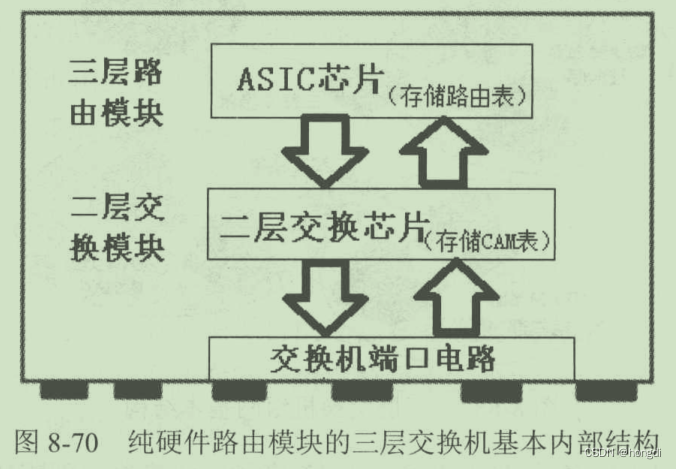
2. Layer 3 switch with pure hardware routing module
The technology is complex and the cost is high, but it is fast, has good performance and has strong load capacity. The principle is to use a specialized ASIC chip to search and refresh the routing table.
Different from pure software, the ASIC ( Application Specific Integrated Circuit ) chip is used for routing selection and forwarding. The routing table information is stored in the ASIC chip and the execution efficiency is high.
3. Layer 3 switch combining software and hardware with routing module
Currently more adopted. The ASIC chip simultaneously stores the second-layer CAM table and the third-layer forwarding table, and stores the software routing table and ARP mapping table in the memory, which are called by the CPU. This utilizes the high-speed switching performance of the hardware module and the flexibility of the software module.
The CPU is mainly used for forwarding control, maintaining some software table entries (including software routing tables, software ARP tables, etc.), and configuring the ASIC's hardware Layer 3 forwarding table based on the forwarding information of the software table entries.
What really determines high-speed switching and forwarding are the second- and third-layer hardware entries in the ASIC.
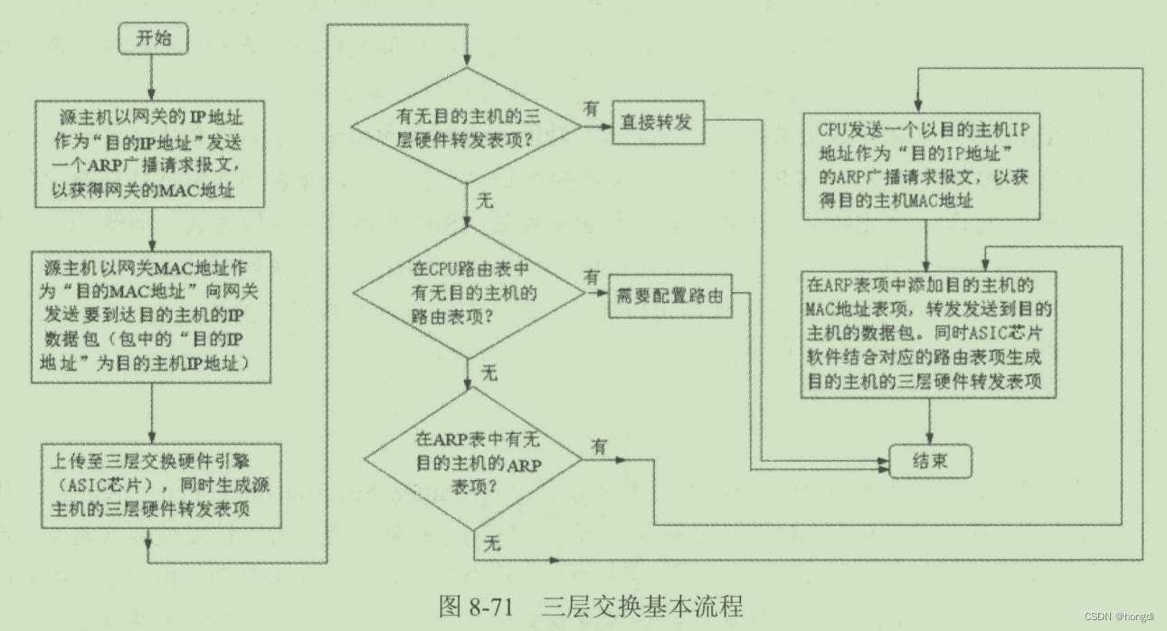
(2) Three-layer switching principle
The overall principle: one routing (the first datagram is forwarded by the CPU's routing table and a three-layer forwarding table entry is established), multiple exchanges (subsequent datagrams are forwarded by the ASIC's three-layer forwarding table).