Recommendation: Use NSDT scene editor to quickly build 3D application scenes
step 1
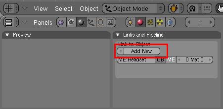
First, you need to create a set of unshaded materials, each with a different color, making sure you have enough materials to cover the model without having the same color overlapping each other. Then, switch to the Shading (F5) panel, select the Material Button, and click the Add New button to add a new material.
Step 2
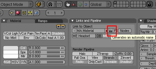
Select the Materials subpanel. Click the "No Shadow" button. Use the "Col" button to change the color from the default gray to a color, or select a color from the color picker. Your entire model will be repainted this color. Note: On the Links and Pipes subpanel you can automatically generate a name for this color using the small button for the car pictured above. This is a very handy tool in this situation, as you will be generating many different colors and trying to remember the index is probably not the best idea.

Step 3
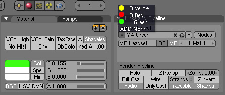
Now add another color to your collection. Click the <> button on the Links and Pipes subpanel below the Link to Object text and select the Add New option. The new color will be created with properties copied from the previous color. So you don't have to keep clicking "No Shadow".

advertise
Step 4
Do the same as the previous color. Use the "Col" button to change the color from the default gray to a color, or select a color from the color picker. Note: Regardless of whether the new color completely replaces the previous color, all previous colors still reside in memory. You can view them by clicking the same "<>" button. Remember, do not save/open the model until all created colors have been assigned to model parts, as Blender will erase all unassigned colors (their names are prefixed with "0"). If you absolutely must stop halfway through and some colors haven't been assigned yet, just press the "F" button next to the material's name when you're done with that material. This will tell Blender to save the colors even if it doesn't have a user.
Follow steps 2 - 4 until the model has enough color. For moderately complex models, 10 should be sufficient. Since the last step is to add a generic gray material, we will need it later.
step 5
Now you need to use materials to divide the model into regions. You'll use color changes to mark the edges you want to control. Switch to edit mode editing panel (F9).
![]()
step 6
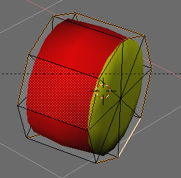
In the 3D View window, select the area where you want one color to be used efficiently and without any edges.
advertise
step 7
Move to the Links and Materials subpanel, select a color using the material selector, and click the Assign button.
Note: If necessary, use the color picker near the material index selector to adjust the color.

step 8
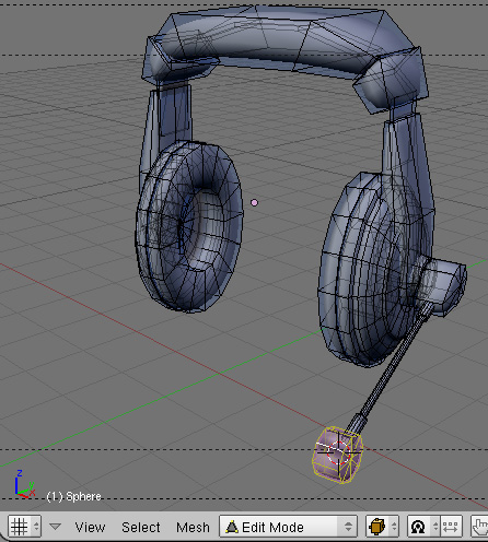
Select another area to color and repeat steps 6 and 7. Note: For each iteration of this step, make sure to select a color other than gray.
Once completed, you should paint the model completely in a different color as shown below.

Step 9
Now you'll use Composite Nodes to filter out all information except edges. First, tell the rendering engine to use compositing nodes. Select the Scene panel (F10), then select the Render Button, then click the Perform Composite button.

Step 10
In the main window, switch the view to the Node Editor.

Step 11
Click the Compound Node and Use Node buttons at the bottom of the Node Editor window. Blender will create two initial nodes for you: the input node "RenderLayer" and the output node "Composite".
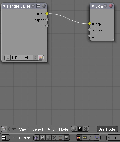
Step 12
Erase a node link by pressing the left mouse button and dragging the outline over the link.
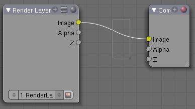
Step 13
To filter out edges, use a node called "Filter" (who knew? Select the "Add-Ins > Filters > Filter" menu item and make sure its "Image" input is linked to the "Render Layer" node's " image" output.

Step 14
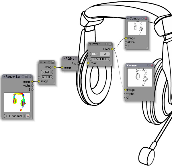
Change the filter type from the default "Soften" to "Sobel". Now, if you link the Filter node output with the Composite node input Image to Image, and run a render, you will see that the model is black and the edges are outlined in a different color.

Step 15
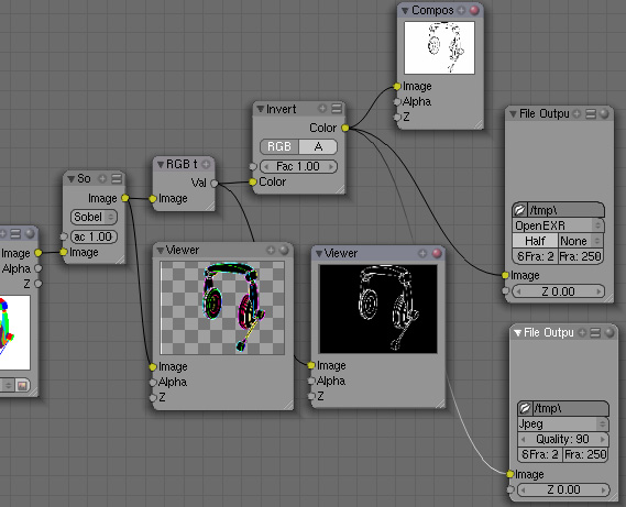
However, you do need the edges to be black. To do this, you must invert the rendering by selecting the "Add > Color > Invert" menu item and linking the added node to the "Image" output of the filter node. Then convert the render from "RGB" to "Black and White" by selecting the "Add>Converter->RGB to BW" menu item. Don't forget to link it to the output of the previous node. The "Val" output of the converter needs to be linked to the "Image" input of the "Composite". Note: You can use the Background option with the Viewer output node to display intermediate results behind the node schema.

Step 16
Run the render to check the results. Note: If you do not plan to change the camera placement and model when building the test flow, you can save the output of this step in a file and use it in subsequent steps. This can significantly reduce rendering times. You can do this by using the "Add->Output->File Output" menu option, specify the file name, and for the file type, use one that will provide lossless compression or no compression at all .
Step 17
Now you need to unfold the model and create a mask texture to cover the edges. Set aside the edges you created and return to your model, along with the gray material you left behind. This part can be tricky. Start with a script-generated UV map and adjust it if necessary. Move back to the 3D View display and switch to edit mode (Tab key). Split the view and in the other window, select the "UV/Image Editor" option as the window type.

Step 18
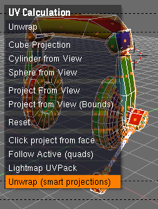
Return to the "3D View", select the entire model, press the "U" key to display the "UV Calculation" menu, and then select the "Expand (Smart Projection)" menu item.
Step 19
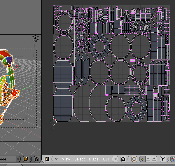
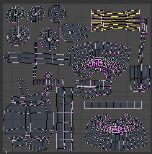
Click the OK button to unwrap the model and check the results in the UV\Image Editor window. If you're lucky, or the model is very simple, you'll get a continuous UV map from the first try. If you like others, you just need to manually expand them step by step.
Step 20
Select the part of the model you want to focus on and press "Ctrl+I" to invert the selection, then press "H" to hide the selection and hide the rest.
Step 21
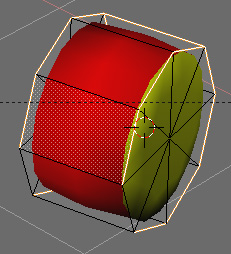
Move to edge selection mode by pressing "Ctrl+Tab" and then "2" and select the edges (seams) along which you want to expand the model.
Step 22
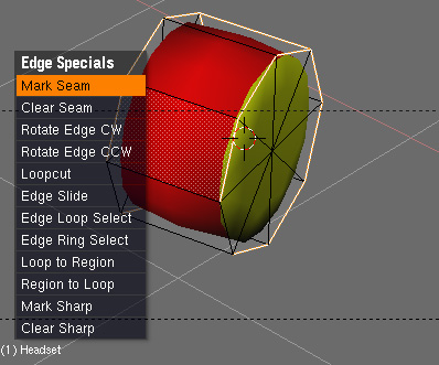
Press "Ctrl+E" to display the Edge Specials menu, which contains a list of edge commands, and select Mark Seams. The selected edges will be outlined in orange, indicating that they are marked as seams.
Step 23
Now try the unpacking process again. Select the entire part of the model you are working with, press the "U" key to display the "UV Calculation" menu, and select the "Unwrap" menu item. UV mapping should now be more logical. If not, you need to choose a better seam and repeat the unfolding process.

Step 24
Unhide the rest of the model and repeat steps 20 - 23 until the entire model is expanded into an easy-to-draw map.
NOTE: Feel free to use the scale and rotate ("S" and "R") keys in the UV Editor to organize your UV shells in a compact and efficient manner.
Step 25
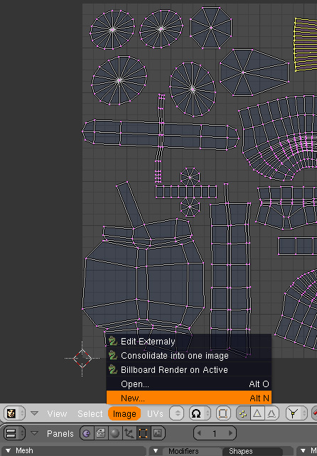
Now you need to create an image for the UV map you created. In the "UV\Image Editor" window, select "Image > New".
Step 26
Specify an image name other than "Untitled," change the image default color to white, and click OK to create the image. To save the image, click "Alt+S" or select the "Image > Save" menu item and save the image. Note: You still need to specify that the image should be used as a texture, assign this texture to the material, and ensure that this texture affects the color of the rendered model.

Step 27
Add this texture to the gray material you have left. To do this, move to the Shading panel (F5), select the Material Button, and then use the material selector on the Links and Pipes tab to select the gray material. On the Textures subpanel, click the Add New button to add a texture draft. Therefore, the Map In and Map To tabs should be displayed.

Step 28
Now, in order to tell the texture to use UV coordinates, select the "Map Input" tab, click the "UV" button and specify the UV texture (not image) name in the "UV:" field. NOTE: To learn the UV texture names, switch to the Edit (F9) panel and the Mech subpanel. This name is specified under the UV Texture field.

Step 29
After that you need to tell the texture what image to use. Go to the Shading panel (F5), then to the Texture Button (F6). In the "Texture Type" field you should see "None". Change it to "Image" and on the "Image" subpanel, click the "Load" button to load the image you created earlier.

Step 30
Now you need to use a composition node to blend the edges generated using the control mask. To do this, you have two options: 1) use the edge rendering you originally created, or 2) use the map you have now. The problem arises is that the initial material set overwrites the texture map you just created. So you need to split your rendering into two parts: time (using a saved image) or using render layers.
For initial modeling and tuning, the first approach is preferable because you can see the rendering results almost immediately after pressing the render button (achieved by skipping the edge generation stage). For animation or practical production, the latter approach is preferable because it reacts to model outline and position changes.
For the purposes of this tutorial, you will use the first method (the second method will be outlined at the end of the tutorial).
Tells the rendering engine to use the model's texture material instead of the color set. Select the Scene panel (F10), then the Render Button, then the Render Layers tab. In the "Mat:" field, enter the name of the gray material you textured previously.

Step 31
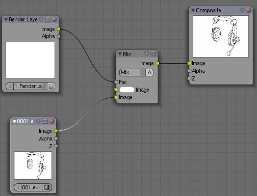
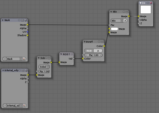
Now modify the compound node to use the saved image. Switch to the Node Editor in the main window, click the Composite Nodes button, and erase all nodes except the Render Layer and Composite nodes. Select the "Add > Input > Image" menu option to add an "Image Input" node to our schema and load the image into it. Now, the only thing left is the blend mask and the resulting edges. To do this, use the Blend node of the Add > Color > Blend menu item. Use a mask as a factor for the white input of the Blend node to specify where to draw on the edge render. The result should be like this. Note: If you run a render, there will be no changes from the initial edge selection scheme. The default image is white, so all edges will be shown.
Step 32
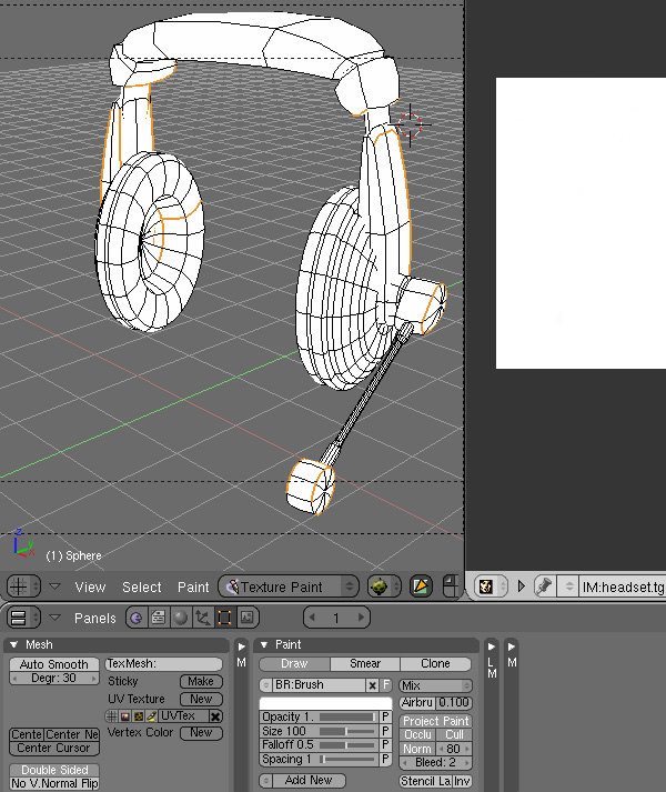
Next, you need to paint the unwanted areas of the mask black. To do this, you need to keep the two window views you used previously (3D view and "UV\Image Editor"). In the 3D View window, select Texture Paint mode and set Viewport Shading to Texture. Then, to see the available painting tools, click Edit (F9) and check the Paint subpanel.
Step 33
To be able to paint in the "UV\Image Editor", click the pencil button to enter painting mode and then press the "C" key to display the available tools.

Step 34
In the Edit > Paint panel, change the color to black, set the opacity to 1, set the size to 25, and then in the 3D View, draw the edges you want to hide.
To limit the painting to only certain faces, switch back to edit mode, select those faces, move back to texture mode, and press the "F" button. Now, when you draw, only the selected faces are affected.
Note: You can also use the "UV\Image Editor" window to make subtle corrections while checking the UV texture outline. The process is exactly the same as for "3D View", only tool selection is available after pressing the "C" key. Also, make sure the "Enable Image Painting" button (pencil) is turned on in the UV window.

Step 35
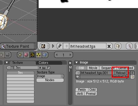
Once done, press "Alt+S" in the "UV\Image Editor" window to save the UV texture, then press "F6" to move to the "Texture Button" and click "Reload" on the "Image" panel to It is reloaded into the material texture.
Step 36
Present and repeat the previous two steps to correct the mapping. Keep repeating until you are satisfied with the results.

Step 37
Now we can discuss the second method I mentioned earlier. To do this, you will use the saved edge image used in the compound node. After adjusting your process, you may want to combine the two processes to eliminate the need to save the image. To do this, add a copy of the render layer without covering the material, and assemble the composite map as described below. Now, all that's left to do is hit render and enjoy the results.

Original link: Advanced edge control and texture mapping in Blender (mvrlink.com)