[USparkle column] If you have great skills, love to "do some research", are willing to share and learn from others, we look forward to your joining, let the sparks of wisdom collide and interweave, and let the transmission of knowledge be endless!
I. Overview
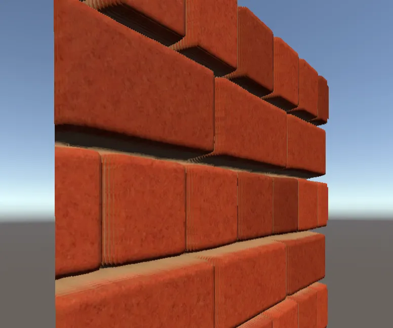
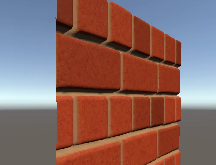
Parallax Mapping (Parallax Mapping) is a texture technology similar to normal maps. They can significantly enhance the surface details of the model/texture and give it a sense of bumpiness, but the bumpiness brought by the normal map will not change with the viewing angle. Change will not block each other. For example, if you look at a real brick wall, at a viewing angle that is more perpendicular to the wall, you can't see the gaps between the bricks, and the normal map of the brick wall will never show this type of occlusion, because it Only normals are changed to affect the result of direct lighting.

So it's better to let the bump actually affect the position of each pixel on the surface, we can achieve this requirement through the height map.

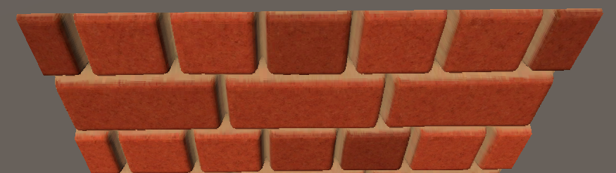
The easiest way is to use a large number of vertices, and then offset the vertex position coordinates according to the height value sampled from the above image—displacement mapping (Displayment Mapping) , you can get the effect of the left image in the image below (the vertex density is 100* 100). However, such a number of vertices is not acceptable for real-time rendering games (or worth optimizing), and if the number of vertices is too small, there will be a very uneven block phenomenon, as shown in the right picture in the figure below (vertex density is 10* 10). So some smart people came up with the ability to offset the vertex texture coordinates - Parallax Mapping (Parallax Mapping) , so that we can use a Quad to create the real effect of the left picture in the picture below, first put the source code .

2. Principle
So how to offset the texture coordinates to make the bump? We must start with what we have observed:
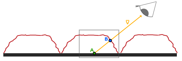
Assuming that we really have such a rough, uneven surface (such as obtained by dense vertex offset), then when we look at the surface with a certain line of sight direction V, what we should see is point B (that is, line of sight and height map intersection ). But as we said before, we are using a Quad, so what we actually see should be point A. The function of parallax mapping is to offset the texture coordinates at A to the texture coordinates at B, so that even if the point we see is A, the sampling result is at B, thus simulating the height difference, so what we have to solve is how to Get the texture coordinates at B at A.

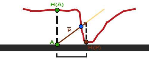
Carefully observe the above picture, in fact, A and B are both on the straight line where the line of sight direction V is located, so our offset direction is the normalized line of sight direction, and the offset is the result H(A) of the sampling height map at A, So the offset vector is P ¯ in the figure, and we need to offset along the plane where the texture coordinate (UV) is located, so the offset is the projection of P ¯ on the plane, then what we actually see to point A is in the figure H(P), which means that what we get is actually a result similar to point B.
Because we need to offset along the plane where the texture coordinates (UV) are located, it is necessary to choose the tangent space (that is, turn the view direction to the tangent space and then offset the texture coordinates), so that we don't have to worry about the model having any The offset when rotating is not along the UV plane anymore. See the normal map for the principle , which is why it is strongly recommended that you first understand the normal map at the beginning.
The offset result Padj obtained for the texture coordinate P of any point, the normalized line of sight direction V, and the height map sampling result h:
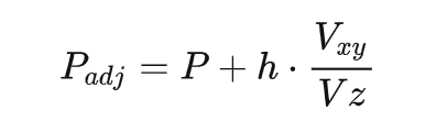
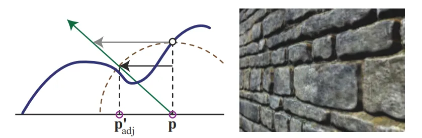
Dividing by the Z component is for normalization: because the Z component is larger when the line of sight is more perpendicular to the plane. But when the line of sight is close to parallel to the plane, the Z component is very small. Dividing it by the Z component will make the offset too large. Pay attention to the gap in the picture below (using the original height map example).

In order to improve this problem, we can limit the offset so that it will never be greater than the actual height (the offset should be the vector indicated by the gray arrow line in the figure below, but after the limit is the vector indicated by the black arrow line). The equation is Padj=P+h*Vxy (that is, it is not divided by the Z component, and the calculation speed is faster).

But because the XY component of the viewing direction will still become larger as the viewing direction is more parallel to the plane, the offset will still become larger.
There is another problem: In most cases, our above approach can get good results, but the results may not be satisfactory when the altitude changes rapidly: the obtained result H(P) is very different from point B (blue point) Far.
Three, realize
1. Parallax mapping
We can make a simple attempt based on the basic principles mentioned in the previous Part. Here we will still use the normal map, because I also said in the article summarizing the normal map that the normal map is often based on height. The texture is calculated, but the normal map affects the normal, and the bump details are expressed through lighting, while the parallax mapping uses the offset texture coordinates to obtain the sampling results of other positions to express the height, so the combination of the two is like a combination of two swords , the power greatly increased.
float2 ParallaxMapping(float2 uv, half3 viewDir)
{
    float height = tex2D(_HeightMap, uv).r * _HeightScale;
    float2 offset = 0;
#if _OFFSETLIMIT //为了对比是否限制偏移量的效果
    offset = viewDir.xy;
#else
    offset = viewDir.xy / viewDir.z;
#endif
    float2 p = offset * height;
    return uv - p;
}

half3 viewDirWS = normalize(UnityWorldSpaceViewDir(positionWS));
float2 uv = i.uv.xy;
#ifdef _PARALLAXMAPPING
    half3 viewDirTS = normalize(mul(viewDirWS, float3x3(i.T2W0.xyz, i.T2W1.xyz, i.T2W2.xyz)));
    uv = ParallaxMapping(uv, viewDirTS);
#endif
//然后用偏移后的纹理坐标采样各种贴图即可

You can see that after offsetting the texture coordinates there may be a problem with the position of the edge, because the edge may be outside the range of 0 to 1 after offsetting. For Quad, you can simply discard the part that is out of range, but for other complex Simply discarding the model may not solve the problem.
if (uv.x > 1 || uv.y > 1 || uv.x < 0 || uv.y < 0)
    discard;

In Unity's Shader source code, we also provide us with the parallax mapping function:
// Calculates UV offset for parallax bump mapping
inline float2 ParallaxOffset( half h, half height, half3 viewDir )
{
    h = h * height - height/2.0;
    float3 v = normalize(viewDir);
    v.z += 0.42;
    return h * (v.xy / v.z);
}
Although the current effect is good enough, the two problems raised at the end of the previous Part still exist. Section 6.8.1 of the fourth edition of Real Time Rendering provides a lot of reference materials to solve these problems, which we summarize below The most common of them, if you want to understand more deeply, I recommend you to read the original text.
2. Steep parallax mapping
The root cause of the two problems mentioned at the end of the previous Part is that the offset is too large, so we can follow the example of Ray Marching and use the approach of gradual approximation to find the appropriate offset. But this will inevitably require multiple sampling, and the performance consumption will be greater. The initial use of this idea is steep parallax mapping (Steep Parallax Mapping).
As shown in the figure below, divide the depth range (0 (plane position) -> 1 (maximum sampling depth)) into multiple layers with the same depth h (the lower layer depth h=0.2), and find the texture offset corresponding to the layer depth h Shift huv, and then traverse each layer from top to bottom: use huv to offset the texture coordinates, and sample the height map. If the depth value of the current layer is less than the sampled value, we continue to go down until the depth of the current layer Sampling results larger than the heightmap, meaning we found the first layer below the surface (i.e. where the intersection of the line of sight and the heightmap is considered detected, albeit approximate ).

float2 ParallaxMapping(float2 uv, float3 viewDir)
{
    // 优化:根据视角来决定分层数(因为视线方向越垂直于平面,纹理偏移量较少,不需要过多的层数来维持精度)
    float layerNum = lerp(_MaxLayerNum, _MinLayerNum, abs(dot(float3(0,0,1), viewDir)));//层数
    float layerDepth = 1 / layerNum;//层深
    float2 deltaTexCoords = 0;//层深对应偏移量
#if _OFFSETLIMIT //建议使用偏移量限制,否则视线方向越平行于平面偏移量过大,分层明显
    deltaTexCoords = viewDir.xy / layerNum * _HeightScale;
#else
    deltaTexCoords = viewDir.xy / viewDir.z / layerNum * _HeightScale;
#endif
    float2 currentTexCoords = uv;//当前层纹理坐标
    float currentDepthMapValue = tex2D(_HeightMap, currentTexCoords).w;//当前纹理坐标采样结果
    float currentLayerDepth = 0;//当前层深度
    // unable to unroll loop, loop does not appear to terminate in a timely manner
    // 上面这个错误是在循环内使用tex2D导致的,需要加上unroll来限制循环次数或者改用tex2Dlod
    // [unroll(100)]
    while(currentLayerDepth < currentDepthMapValue)
    {
        currentTexCoords -= deltaTexCoords;
        // currentDepthMapValue = tex2D(_HeightMap, currentTexCoords).r;
        currentDepthMapValue = tex2Dlod(_HeightMap, float4(currentTexCoords, 0, 0)).r;
        currentLayerDepth += layerDepth;
    }
    return currentTexCoords;
}
Now the effect is almost realistic:

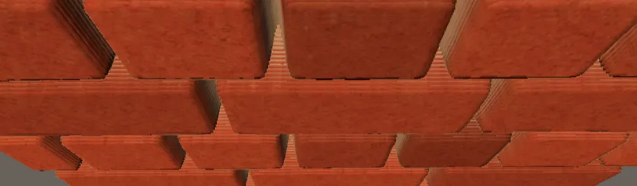
But when we look at it from an angle that is more parallel to the surface, even though the number of layers increases with the viewing angle, there is still a clear layering phenomenon:
The easiest way is to keep increasing the number of layers, but this is bound to greatly affect performance (in fact, it is already serious). There are methods aimed at fixing this: instead of the first layer below the surface, do it between the depth layers before and after the intersection (between the last layer above the surface and the first layer below the surface) Interpolate to find better matching intersection locations . The two most popular solutions are called Relief Parallax Mapping and Parallax Occlusion Mapping. Relief Parallax Mapping is more accurate, but has more performance overhead than Parallax Occlusion Mapping. Let's take a look at these two plan.
3. Parallax occlusion mapping
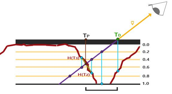
The distance between the height map sampling value of the depth layer before and after the intersection and the depth value of the two layers is used as the weight of linear interpolation, and then the texture coordinates corresponding to the two layers before and after the intersection are linearly interpolated. H(T3) and H(T2) in the figure below are two similar triangles with blue lines, purple lines, and yellow lines respectively. The length of the blue line is the distance between the height map sampling value and the corresponding layer depth, so that we can use Similar triangles get the ratio between the purple lines, which can directly correspond to the texture coordinate offset result (that is, the offset corresponding to Tp, so it is closer to the intersection point).
// 陡峭视差映射的代码
//......
// get texture coordinates before collision (reverse operations)
float2 prevTexCoords = currentTexCoords + deltaTexCoords;
// get depth after and before collision for linear interpolation
float afterDepth  = currentDepthMapValue - currentLayerDepth;
float beforeDepth = tex2D(_HeightMap, prevTexCoords).r - currentLayerDepth + layerDepth;
// interpolation of texture coordinates
float weight = afterDepth / (afterDepth - beforeDepth);
float2 finalTexCoords = prevTexCoords * weight + currentTexCoords * (1.0 - weight);

return finalTexCoords;

4. Relief Parallax Mapping
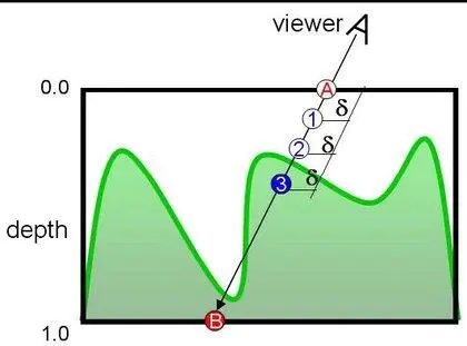
Before talking about relief parallax mapping, let's take a look at relief mapping: instead of layering like steep parallax mapping, we find the best value between the depth range (0->1) by dichotomy:

As shown in the figure, we take the midpoint 1 of AB, replace B with 1, then take the midpoint 2 between 1 and A, replace A with 2, and then take the midpoint 3 between 1 and 2, which is what we want The intersection of the line of sight and the height map, this is the flow of the dichotomy. But in some cases, problems can arise:

In the direction of the line of sight in the picture, we will get 3 by using the dichotomy method, but in fact 3 has been blocked, and what we get should be the blue dot above. At this time, we can use the result of steep parallax mapping: as shown in the figure below, first find the first layer (3) below the surface through steep parallax mapping, and then do a binary search with A, which is why it is called relief parallax mapping.
But it can still be optimized, because the steep parallax map can already get the depth layer before and after the intersection (the last layer above the surface and the first layer below the surface, such as 2 and 3 in the above figure), then we directly here Binary search between two depth layers is enough: it is enough to understand through the code, in fact, it is more subdivided, so it is more accurate than parallax occlusion mapping. There is still a slight delamination, but it is mostly invisible. And because the depth difference between two adjacent layers is the layer depth, there is no need to calculate the last position higher than the surface like parallax occlusion mapping, but obviously the latter does not need to be subdivided but interpolated, so the performance is better.
// 陡峭视差映射的代码
//......
// 二分查找
float2 halfDeltaTexCoords = deltaTexCoords / 2;
float halfLayerDepth = layerDepth / 2;
currentTexCoords += halfDeltaTexCoords;
currentLayerDepth += halfLayerDepth;

int numSearches = 5; // 5次基本上就最好了,再多也看不出来了
for(int i = 0; i < numSearches; i++)
{
halfDeltaTexCoords = halfDeltaTexCoords / 2;
halfLayerDepth = halfLayerDepth / 2;
currentDepthMapValue = tex2D(_HeightMap, currentTexCoords).r;
if(currentDepthMapValue > currentLayerDepth)
{
currentTexCoords -= halfDeltaTexCoords;
currentLayerDepth += halfLayerDepth;
}
else
{
currentTexCoords += halfDeltaTexCoords;
currentLayerDepth -= halfLayerDepth;
}
}

return currentTexCoords;
5. Adding shadows
is the best way to show occlusion, and it is also very necessary. Currently, the brick wall we use has a small offset depth, so shadows without self-occlusion look good, but the effect after adding shadows To be even more awesome (and of course more suitable for larger offset depths):

The idea of making shadows is simpler. We can use the results of parallax occlusion mapping to find the intersection point upwards. If there is, it means that it is occluded, and the intensity of the shadow can be determined according to the number of intersection points, because the deeper the easier If the shadow is blocked, the more the number of intersection points, the stronger the shadow, so that a shadow with a smooth transition between light and dark can be made.
// 输入的initialUV和initialHeight均为视差遮挡映射的结果
float ParallaxShadow(float3 lightDir, float2 initialUV, float initialHeight)
{
float shadowMultiplier = 1; //默认没有阴影
if(dot(float3(0, 0, 1), lightDir) > 0) //Lambert
{
                //根据光线方向决定层数(道理和视线方向一样)
float numLayers = lerp(_MaxLayerNum, _MinLayerNum, abs(dot(float3(0, 0, 1), lightDir)));
float layerHeight = 1 / numLayers; //层深
float2 texStep = 0; //层深对应偏移量
        #if _OFFSETLIMIT
        texStep = _HeightScale * lightDir.xy / numLayers;
        #else
                texStep = _HeightScale * lightDir.xy / lightDir.z / numLayers;
        #endif
                // 继续向上找是否还有相交点
float currentLayerHeight = initialHeight - layerHeight; //当前相交点前的最后层深
float2 currentTexCoords = initialUV + texStep;
float heightFromTexture = tex2D(_HeightMap, currentTexCoords).r;
                float numSamplesUnderSurface = 0; //统计被遮挡的层数
while(currentLayerHeight > 0) //直到达到表面
{
if(heightFromTexture <= currentLayerHeight) //采样结果小于当前层深则有交点
numSamplesUnderSurface += 1;

currentLayerHeight -= layerHeight;
currentTexCoords += texStep;
heightFromTexture = tex2Dlod(_HeightMap, float4(currentTexCoords, 0, 0)).r;
}
shadowMultiplier = 1 - numSamplesUnderSurface / numLayers; //根据被遮挡的层数来决定阴影强度
}
return shadowMultiplier;
}

The practice of soft shadow: the optimization is in the comments, which can be compared with the above code. The point is not to determine the intensity of the shadow based on the number of intersecting layers!!!
// 输入的initialUV和initialHeight均为视差遮挡映射的结果
float ParallaxShadow(float3 lightDir, float2 initialUV, float initialHeight)
{
    float shadowMultiplier = 0;
    if (dot(float3(0, 0, 1), lightDir) > 0) //只算正对阳光的面
    {
        // 根据光线方向决定层数(道理和视线方向一样)
float numLayers = lerp(_MaxLayerNum, _MinLayerNum, abs(dot(float3(0, 0, 1), lightDir)));
float layerHeight = initialHeight / numLayers; //从当前点开始计算层深(没必要以整个范围)
        float2 texStep = 0; //层深对应偏移量
    #if _OFFSETLIMIT
texStep = _HeightScale * lightDir.xy / numLayers;
    #else
        texStep = _HeightScale * lightDir.xy / lightDir.z / numLayers;
    #endif
        // 继续向上找是否有相交点
float currentLayerHeight = initialHeight - layerHeight; //当前相交点前的最后层深
float2 currentTexCoords = initialUV + texStep;
float heightFromTexture = tex2D(_HeightMap, currentTexCoords).r;
int stepIndex = 1; //向上查找次数
        float numSamplesUnderSurface = 0; //统计被遮挡的层数
while(currentLayerHeight > 0) //直到达到表面
{
    if(heightFromTexture < currentLayerHeight) //采样结果小于当前层深则有交点
            {
numSamplesUnderSurface += 1;
                float atten = (1 - stepIndex / numLayers); //阴影的衰减值:越接近顶部(或者说浅处),阴影强度越小
                // 以当前层深到高度贴图采样值的距离作为阴影的强度并乘以阴影的衰减值
float newShadowMultiplier = (currentLayerHeight - heightFromTexture) * atten;
shadowMultiplier = max(shadowMultiplier, newShadowMultiplier);
    }

    stepIndex += 1;
    currentLayerHeight -= layerHeight;
    currentTexCoords += texStep;
    heightFromTexture = tex2Dlod(_HeightMap, float4(currentTexCoords, 0, 0)).r;
}

if(numSamplesUnderSurface < 1) //没有交点,则不在阴影区域
    shadowMultiplier = 1;
else
    shadowMultiplier = 1 - shadowMultiplier;
    }
    return shadowMultiplier;
}

4. Production method
1. Grayscale values of procedural textures
A large number of procedural texture generation techniques can be utilized (noise, SDF, computational geometry...)
2. Calculating the relationship between light and shade
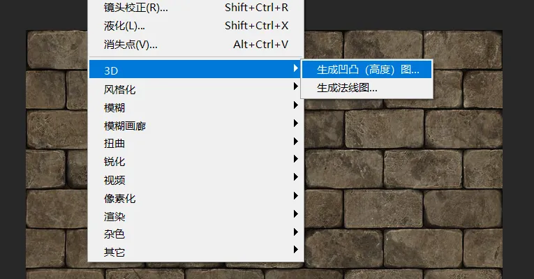
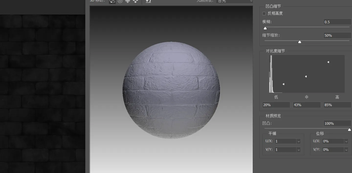
The color map (Albedo/Diffuse) we use often contains rich light and shade details, such as Photo Shop > Filter > 3D > Generate bump (height) map, one of the information that can be used is the built-in The relationship between light and shade (for example, the gap in the wall in the picture below is black)
3. Draw + use image processing
4. Generate high-precision models.
As we said earlier, a common practice in game development is to create high-precision models in modeling software. After adjusting the effects, they can be simplified into low-precision meshes and imported into the engine. The high-precision models themselves are A large number of vertex performance details are used, which can be made with sculpting tools, and the modified amount can be written into a texture after UV development and exported as a height map.
5. Application
Parallax mapping is a very good technology to improve the details of the scene, you can seek incredible effects, but when using it, you still have to consider that it will bring a little unnaturalness, so most of the time parallax mapping is used on the ground and wall surfaces, in these cases Pinpointing the contour of a surface is not easy, and the viewing direction tends to tend to be perpendicular to the surface. In this way, the unnaturalness of the disparity mapping is difficult to be noticed.
1. Wall surface: generated by PS

2. Terrain cracks: hand-painted
Terrain Cracks Based on Parallax Mapping
3. Dynamic Cloud and Fog Simulation: Using Noise
Dynamic clouds and fog using parallax mapping
4. Trajectories on Terrain: Dynamically Generated
This is the 1403rd article of Yuhu Technology, thanks to the author for contributing. Welcome to repost and share, please do not reprint without the authorization of the author. If you have any unique insights or discoveries, please contact us and discuss together.
Author's homepage: https://www.zhihu.com/people/LuoXiaoC
Thanks again for your sharing. If you have any unique insights or discoveries, please contact us and discuss together.