Premise: You can first read the motor column 2. BLDC commutation principle with Hall sensor_lakers_cbb's blog-CSDN blog . The notes are first organized from Youdao Cloud Notes, and the format may be wrong. If you want to see Youdao Cloud Notes, you can send a link in a private message. Or readers who need it can comment below, and will share the links of Youdao Cloud notes, including C++, Linux, GNSS navigation, automatic driving, QT, C language, C#, Python, STM32, etc. Share your notes. In the follow-up topic on motors, the author will upload the source code of algorithms such as motors, navigation, and automatic driving.
1. BLDC speed unit
@1. In the motor field, the unit of speed is circle/second or circle/minute
@2. Circle/minute means how many circles the motor rotates in one minute, the unit is RPM (Revolutions Per Minute)
2. Sensitive BLDC speed measurement scheme with Hall sensor
@1. BLDC motor speed measurement with Hall is accurate. The Hall sensor itself outputs U, V, W three-phase waveforms according to the change of the electromagnetic field. The U, V, and W three-phase lines are connected to the controller system, and the high and low level changes of the Hall U, V, and W three-phase inputs are collected according to the method of rising edge + falling edge double-edge interruption.
@2. Hall U, V, W three-phase waveform period (period) and duty cycle (duty) are regarded as exactly the same in unit time. So we take out one phase of U, V, W to analyze.
@3. Suppose we take the U phase to analyze. Connect the U phase to the input capture pin of a timer of the controller.
@4. Configure this input to capture the frequency Ft of the timer. By configuring the appropriate frequency Ft, and the frequency Ft and the number of bits of the counter of the timer (generally 12 bits, 16 bits, 32 bits), the overall configuration can calculate the captured high The maximum time of the level interval, that is, C*(1/Ft) is the maximum time of the high level interval of the input capture timer count, assuming that the input capture timer counter is 16
bit, the maximum count value of the captured high level interval is 2^16, which is 65535. The count value Cmax*(1/Ft) can calculate the maximum time for capturing high level. In general, the high and low level intervals of the Hall sensor U, V, and W three-phase frequencies each account for 50% of the unit time, that is to say, the duty cycle can be 50% by default.
Cmax*(1/Ft) * 2 is the pulse cycle time of high and low levels. 1 /(Cmax*(1/Ft) * 2 is to calculate the minimum pulse frequency that can be captured by the input capture timer. The maximum pulse frequency is when the C value is 1, the calculated input capture frequency value can be Capture and amplify the maximum pulse frequency.
@5. The software captures the count value C of a high-level or low-level interval of the U phase. Generally, we will capture the count value C of the high-level interval.
The frequency of the input capture timer is generally called Ft. Through the above analysis, we can get the following calculation formula:
C: Pulse count value during high level
Ft: input capture timer frequency
1/Ft: The time required by the timer timer to capture a pulse value
C*(1/Ft): High level time
C*(1/Ft)*2: high level time + low level time = cycle time
And because: in the BLDC principle, there are several pole pairs, so the motor stator has several cycles in one revolution. Here we assume that the number of pole pairs of the motor is N, then:
C*(1/Ft)*2*N: It is the time for the motor to rotate one circle, the unit is:
2*N*C/Ft sec/turn
But in the field of motors, it is generally said that circles/per second or circles/per minute
2*N*C/Ft is seconds/turn, and the reciprocal relationship is Ft/(2*N*C)turns/second
If it is to be converted into circles/per minute, it is: 60Ft/(2*N*C)
If C is the count value during the high level period, the calculation formula is:
RPM = 60Ft/(2*N*C)
If C is the count value during high level + low level, the calculation formula is:
RPM = 60Ft/(N*C)
3. Non-inductive BLDC speed measurement solution without Hall sensor
@1. The non-inductive BLDC speed measurement scheme without Hall is very complicated. The basic principle is the basis of the counter electromotive force zero-crossing detection scheme through the U, V, W three-phase control circuit of the motor
realized above.
@2. Back EMF zero-crossing detection mainly uses software filtering for high and low speed closed-loop commutation.
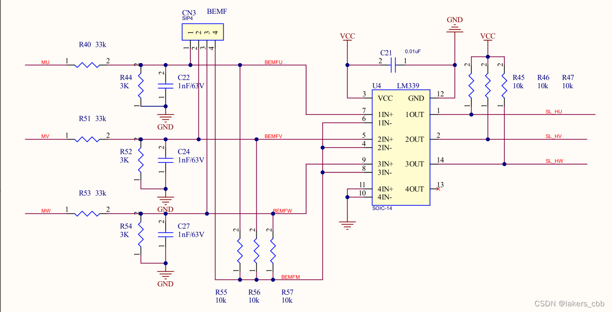
Through a comparator, the change amount of the counter electromotive force is converted into a switch change amount after being compared by the comparator. The implementation principle of the counter electromotive force zero-crossing detection scheme will not be described in detail here. We only analyze the U, V, W three-phase waveforms filtered by the software to calculate the speed method.
Another way is to use the comparator inside the processor, which is the same as the external comparator in principle, but the anti-interference ability is better than the external one.
@3. Analyzing the non-inductive speed measurement scheme will definitely need to compare the sensory speed measurement scheme. Inductive speed measurement is to use the timer timer input capture to capture the timer count value of the high level interval (or high and low level one cycle interval) of one of the Hall U, V, W three phases to calculate the motor Rotating speed. So what kind of solution is the non-inductive speed measurement solution?
@4. First of all, the non-inductive speed calculation cannot be realized according to the way of timer input capture. Because the biggest problem of non-inductive is that the interference of various clutter in the circuit is too serious. If the clutter is not filtered, then the interference and error are too serious to be calculated by using the input capture method to collect the non-inductive zero-crossing waveform cycle. Count value C during the high level period. Through the analysis of the waveform captured by the logic analyzer, the three waveforms in the green box in the figure below are the waveforms filtered by the filtering algorithm for the zero-crossing detection waveform without the Hall-free back EMF, while the waveforms in the red box are the waveforms without the Hall-free back-EMF zero-crossing detection. Zero detection filtered waveform. If the timer input capture method is used, then the high-level period calculation has lost its meaning.
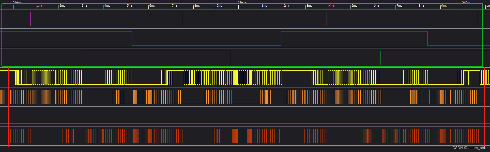
@5. Through the analysis of @4, if we want to calculate the high-level count value, we must filter it first. The filtering method will not be introduced in detail here. The general plan is that the U, V, W three-phase output PWM frequency is 12KHZ, and the timer overflow interrupt is set on the software, which is equivalent to generating an interrupt for each PWM cycle. The interrupt frequency is also 12KHZ, that is, Every 0.083ms, 83us generates an interrupt, and then reads the value of the U, V, W zero-crossing detection IO pins from the interrupt for filtering, after the filtering is completed. These are the three waveforms in the green box shown above.
Of course, if the MCU timer resources are sufficient, we can also create a separate timer, which enters the interrupt at a fixed frequency for non-inductive zero-crossing monitoring point filtering.
@6. After filtering, the high level or high level + low level interval of the pulse wave can be counted, and the count value is recorded as C, and the frequency is the frequency Ft=12KHZ of the timer output PWM.
@7. No Hall sensorless square wave control BLDC speed calculation:
C: Pulse count value during high level
Ft: filter timer (that is, output PWM timer) frequency
1/Ft: The time required by the timer timer to capture a pulse value
C*(1/Ft): High level time
C*(1/Ft)*2: high level time + low level time = cycle time
And because: in the BLDC principle, there are several pole pairs, so the motor stator has several cycles in one revolution. Here we assume that the number of pole pairs of the motor is N, then:
C*(1/Ft)*2*N: It is the time for the motor to rotate one circle, the unit is:
2*N*C/Ft sec/turn
But in the field of motors, it is generally said that circles/per second or circles/per minute
2*N*C/Ft is seconds/turn, and the reciprocal relationship is Ft/(2*N*C)turns/second
If it is to be converted into circles/per minute, it is: 60Ft/(2*N*C)
If C is the count value during the high level period, the calculation formula is:
RPM = 60Ft/(2*N*C)
If C is the count value during high level + low level, the calculation formula is:
RPM = 60Ft/(N*C)