Article Directory
foreword
Environment:
1. Quartus18.1
2. vscode
3. Board model: Atomic Brother Pioneer 2 (EP4CE10F17C8)
Requirements:
Touch the button with your finger, and the led will turn from on to off or from off to on.
1. Introduction of touch buttons
Touch keys can be mainly divided into four categories: resistive, capacitive, infrared induction and surface acoustic wave. According to its different attributes, each touch key has its suitable field of use. We are using capacitive buttons here.
- Capacitive touch key
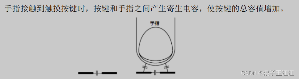
The capacitive touch key is mainly composed of the key IC part and the capacitor part. The button IC part is mainly provided by component suppliers, and is used to convert the change of capacitance into an electrical signal. The capacitive part refers to the capacitive environment of the touch button composed of capacitive plates, grounds, and isolation areas. There is an inductive capacitance between any two conductive objects, and the value of the inductive capacitance is constant when the surrounding environment remains unchanged.
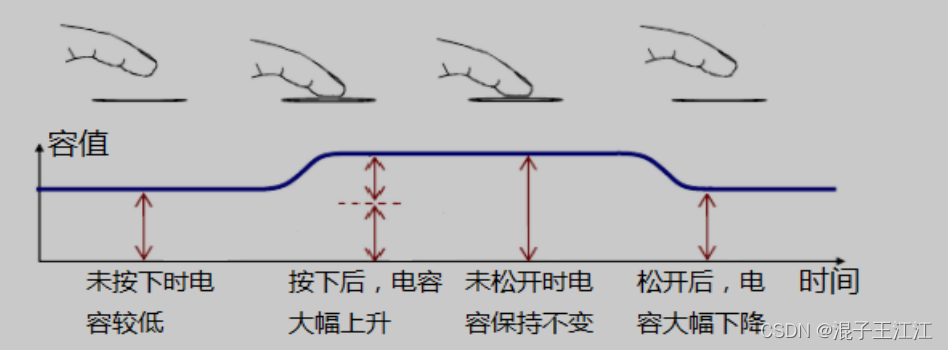
Before and after the touch button is pressed, the change of capacitance is shown in the figure below. After the capacitive touch key IC detects that the sensing capacitance value of the key changes and exceeds a certain threshold, it will output a valid signal to indicate that the key is pressed.
2. The circuit principle of the touch button
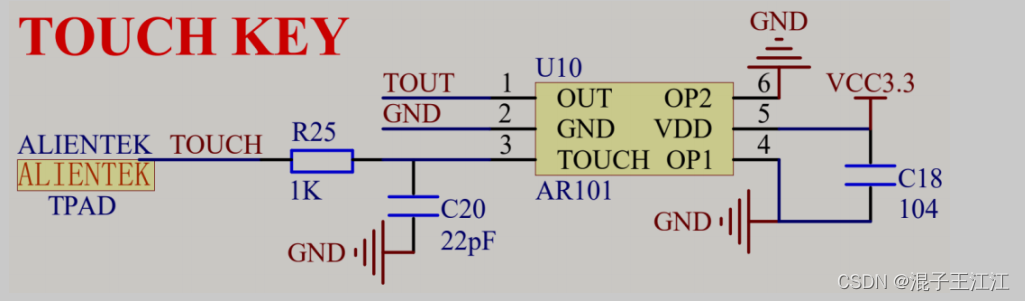
The touch IC model used on the development board is AR101, which can select different working modes through two pins OP1 and OP2 (we choose mode 1 here):
Mode one:
When OP1 is pulled low, the output signal of OUT pin is active at high level; when OP1 is pulled high, the output signal of OUT is active at low level.
Mode two:
When OP2 is pulled low, the touch IC works in synchronous mode (similar to a non-self-locking light touch button), that is, it outputs a valid level when it is touched, and there is no valid level output after it is released; when OP2 is pulled high, the touch IC works in hold Mode (similar to a self-locking button), that is, the active level is output after the touch operation is detected, and the output level remains unchanged after the touch operation is released. When a touch operation is detected again, the output level changes and remains on.
3. System design
1. Module block diagram
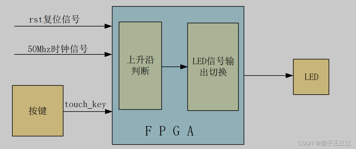
The judgment of the rising edge here uses a very classic beat. Refer to the following article:
https://blog.csdn.net/zerokingwang/article/details/127934270
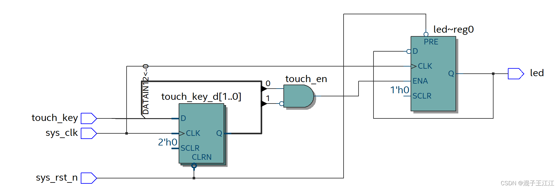
2. RTL view
4. Source code
1. touch_led module
module touch_led(
    input       sys_clk,
    input       sys_rst_n,
    input       touch_key,

    output  reg led
);

reg touch_key_d0;
reg touch_key_d1;

wire touch_en;

assign touch_en = ~touch_key_d1&touch_key_d0;

always @(posedge sys_clk or negedge sys_rst_n)begin
    if(!sys_rst_n)begin
        touch_key_d0 <= 1'b0;
        touch_key_d1 <= 1'b0;
    end
    else begin
        touch_key_d0 <= touch_key;
        touch_key_d1 <= touch_key_d0;
    end
end

always @(posedge sys_clk or negedge sys_rst_n)begin
    if(!sys_rst_n)begin
        led <= 1'b1;
    end
    else begin
        if(touch_en)
            led <= ~led;
        else
            led <= led;
    end
end
endmodule
5. Effect
Touch the button to control the light on and off
6. Summary
The code is actually relatively simple, just try it without using the touch button. The main idea in it is how to judge the rising edge of the pulse signal generated by the touch. We judge the rising edge by tapping and comparing the high and low level changes of the previous signal and the rear signal of the signal.
7. References
The above information comes from the teaching video of punctual atom or the development tutorial of Pioneer 2:
punctual atom official