10_Read DHT11 temperature and humidity data based on RASC-based keil electronic clock production
overview
This article introduces how to drive the DH11 humidity sensor and realize the current serial port data printing.
DHT11 digital temperature and humidity sensor is a temperature and humidity composite sensor with calibrated digital signal output.
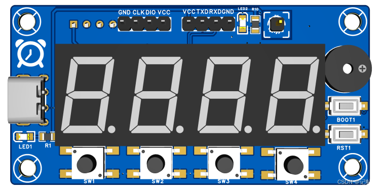
hardware preparation
First, you need to prepare a development board. Here I am preparing a development board with chip model R7FA2E1A72DFL:
video tutorial
https://www.bilibili.com/video/BV1e94y1C7YV/
Production of keil electronic clock based on RASC (Renesas RA)----(10) Read DHT11 temperature and humidity data
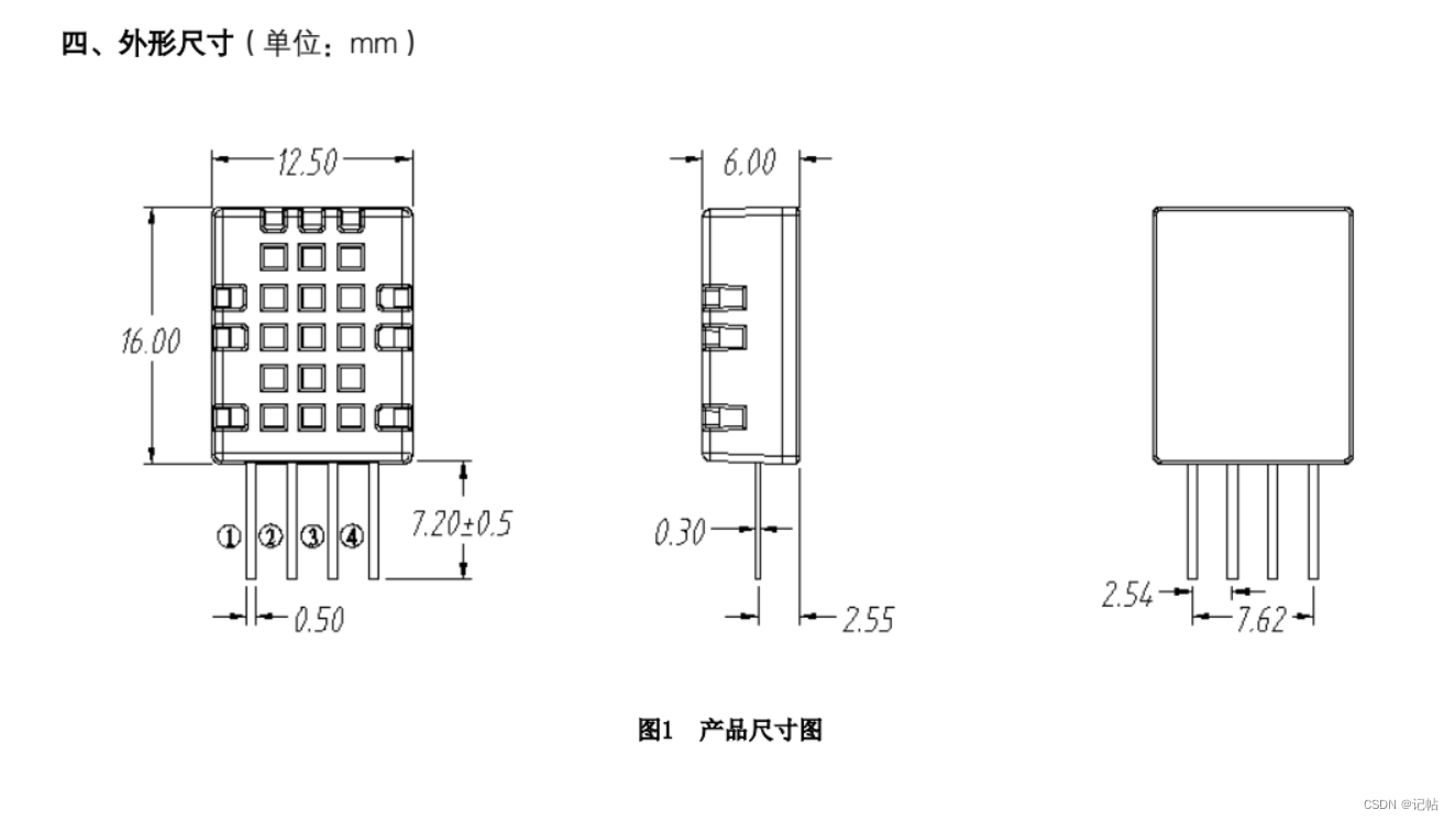
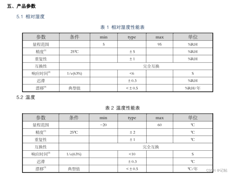
Product parameters
The temperature measurement range is -20-60°C, and the humidity range is 5-95%RH.
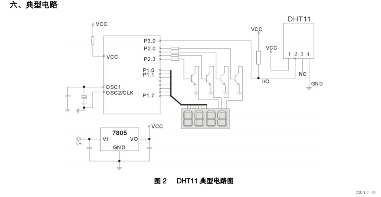
circuit setup
1. In the typical application circuit, it is recommended to use a 4.7K pull-up resistor when the length of the connecting wire is shorter than 5m, and reduce the
resistance value of the pull-up resistor according to the actual situation when the length is longer than 5m.
2. When using 3.3V voltage for power supply, the connection wire should be as short as possible. If the wire is too long, the power supply of the sensor will be insufficient, resulting in measurement deviation.
3. The temperature and humidity value read out each time is the result of the last measurement. To obtain real-time data, it needs to be read twice in a row. However, it is not recommended to read the sensor multiple times in a row. The interval between
each reading of the sensor is greater than 2 seconds. Get accurate data.
4. If the power part fluctuates, it will affect the temperature. If the ripple of the switching power supply is too large, the temperature will fluctuate.
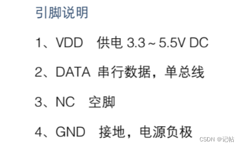
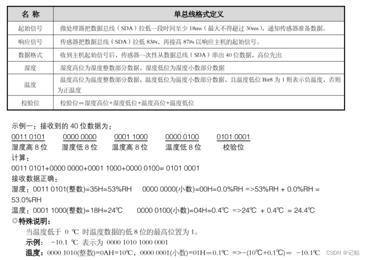
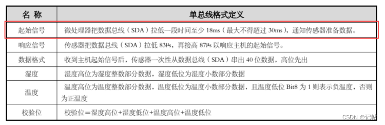
Data Format
The DHT11 device employs simplified single-wire communication. The single bus means that there is only one data line, and the data exchange and control in the system are all completed by the single bus. The device (master or slave) is connected to the data line through an open-drain or tri-state port to allow the device to release the bus when not sending data, and let other devices use the bus; a single bus usually requires an external connection of about 4.7kΩ pull-up resistors, so that when the bus is idle, its state is high. Because they are master-slave structures, only when the master calls the slave, the slave can answer, so the master must strictly follow the single-bus sequence when accessing the device. If the sequence is disordered, the device will not respond to the master.
DATA is used for communication and synchronization between the microprocessor and DHT11, adopts single-bus data format, and transmits 40-bit data at a time, high-order first out.
Data format:
8bit humidity integer data + 8bit humidity decimal data + 8bit temperature integer data + 8bit temperature decimal data + 8bit check digit.
Note: The decimal part of the humidity is 0.
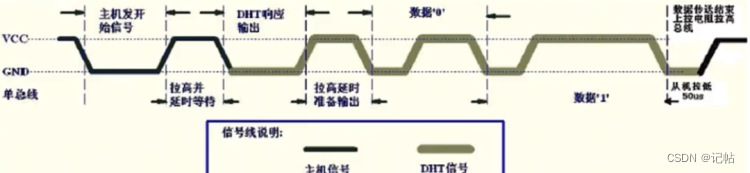
Data reading steps
Step 1:
After the DHT11 is powered on (after the DHT11 is powered on, wait for 1S to overcome the unstable state and cannot send any commands during this period), test the ambient
temperature and humidity data, and record the data, and at the same time, the DHT11 DATA data line is pulled by the pull-up resistor High keeps high level all the time; at this time, the DATA pin of DHT11 is in the input state and detects external signals all the time.
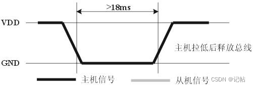
Step 2:
Set the I/O of the microprocessor to output and output low level at the same time, and the low level should not be kept for less than 18ms (the maximum should not exceed 30ms),
and then the I/O of the microprocessor is set to the input state. Pull the resistor, the I/O of the microprocessor, that is, the DATA data line of DHT11 will also become high, waiting for the reply signal from DHT11, and the sending signal is as shown in the figure:
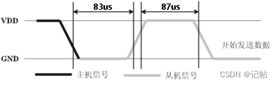
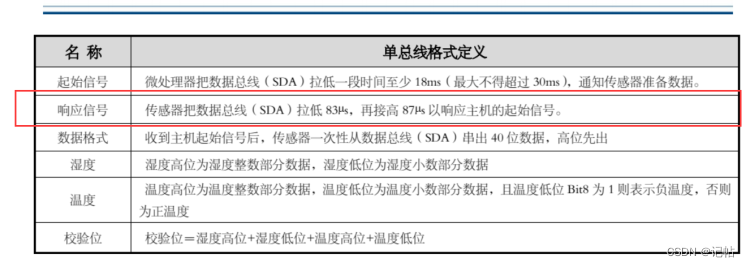
Step 3:
When the DATA pin of DHT11 detects that the external signal has a low level, wait for the end of the low level of the external signal. After the delay, the DATA pin of DHT11 is in the output state, and output a low level for 83 microseconds as a response signal, and then Output a high level of 87 microseconds to notify the peripherals to receive data. The I/O of the microprocessor is in the input state at this time. After detecting that the I/O has a low level (DHT11 response signal), wait for a high level of 87 microseconds The data receiving and sending signals after the level are shown in the figure:
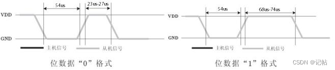
40-bit data is output by the DATA pin of DHT11, and the microprocessor receives 40-bit data according to the change of I/O level. The format of bit data "0" is: 54 microseconds low level and 23-27 microseconds high Level, the format of bit data "1" is: 54 microseconds low level plus 68-74 microseconds high level. Bit data "0", "1" format signal as shown in the figure:
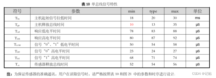
The collated data is shown below.
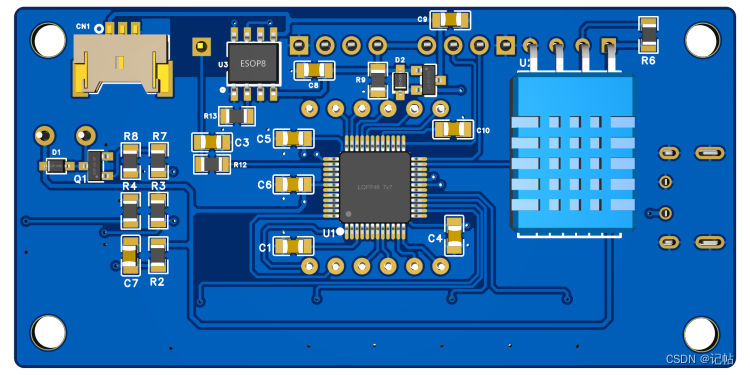
GPIO settings
The DHT11 temperature and humidity module is as follows.
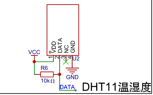
The corresponding data port is shown below, which is P301.

Due to the need to configure
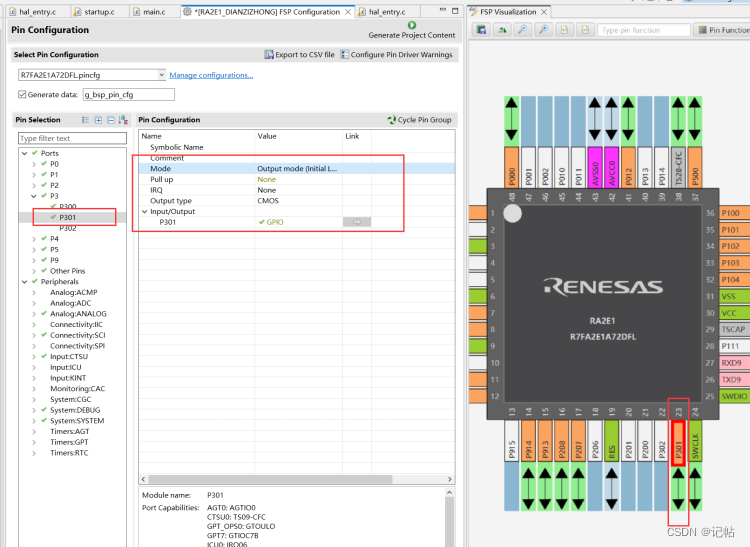
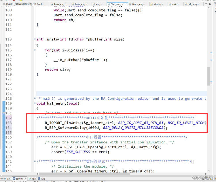
In the above, you can add a delay of 1s to let the program run, so that the temperature and humidity sensor is stable.
/**********************DHT11初始化***************************************/
    R_IOPORT_PinWrite(&g_ioport_ctrl, BSP_IO_PORT_03_PIN_01, BSP_IO_LEVEL_HIGH);
    R_BSP_SoftwareDelay(1000U, BSP_DELAY_UNITS_MILLISECONDS);
IO modification can be done through R_IOPORT_PinCfg().
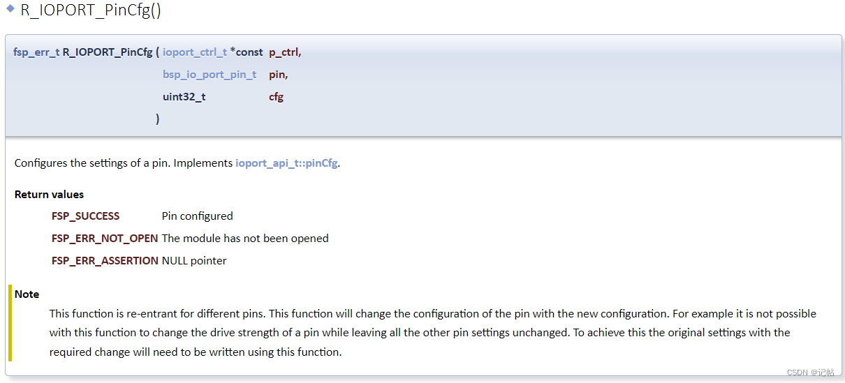
For example set to input state.
   //DATA设为输入状态
    R_IOPORT_PinCfg(&g_ioport_ctrl,BSP_IO_PORT_03_PIN_01,((uint32_t) IOPORT_CFG_PORT_DIRECTION_INPUT));
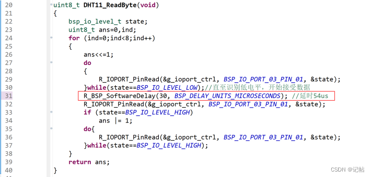
Read temperature and humidity data
Since the internal crystal oscillator is used, the accuracy is definitely not as good as the external crystal oscillator, and the corresponding time needs to be slightly modified.
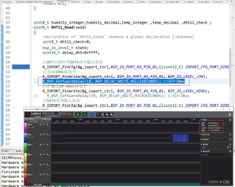
The starting signal is shown in the figure below.
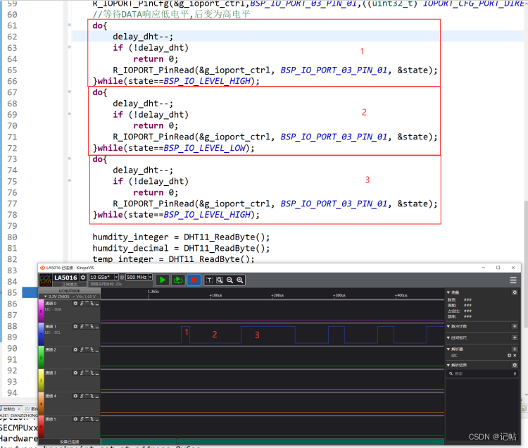
The corresponding signals are shown in the figure below.
If the data cannot be read normally, the following us delay can be modified appropriately.
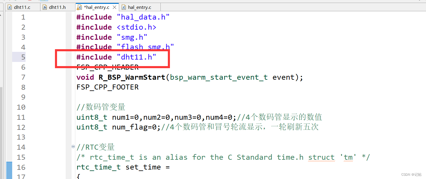
Note that the corresponding header file is introduced in the main program.
#include "dht11.h"
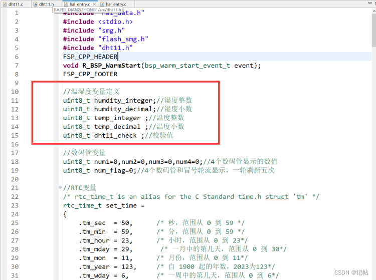
The temperature and humidity variables need to be defined in the main program.
//温湿度变量定义
uint8_t humdity_integer;//湿度整数
uint8_t humdity_decimal;//湿度小数
uint8_t temp_integer ;//温度整数
uint8_t temp_decimal ;//温度小数
uint8_t dht11_check ;//校验值
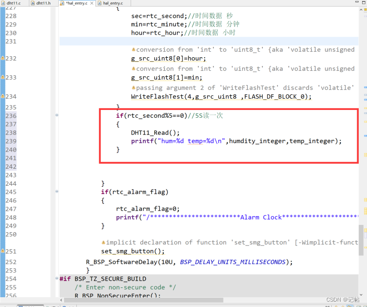
Read data every 5S in the main program.
               if(rtc_second%5==0)//5S读一次
               {


                   DHT11_Read();
                   printf("hum=%d temp=%d\n",humdity_integer,temp_integer);

               }
dht11.c
/*
 * dht11.c
 *
 *  Created on: 2023年6月29日
 *      Author: a8456
 */
#include "dht11.h"


extern fsp_err_t err ;


uint8_t DHT11_ReadByte(void)
{


    bsp_io_level_t state;
    uint8_t ans=0,ind;
    for (ind=0;ind<8;ind++)
    {


        ans<<=1;
        do
        {


            R_IOPORT_PinRead(&g_ioport_ctrl, BSP_IO_PORT_03_PIN_01, &state);
        }while(state==BSP_IO_LEVEL_LOW);//直至识别低电平,开始接受数据
        R_BSP_SoftwareDelay(30, BSP_DELAY_UNITS_MICROSECONDS); //延时54us
        R_IOPORT_PinRead(&g_ioport_ctrl, BSP_IO_PORT_03_PIN_01, &state);
        if (state==BSP_IO_LEVEL_HIGH)
            ans |= 1;
        do{


            R_IOPORT_PinRead(&g_ioport_ctrl, BSP_IO_PORT_03_PIN_01, &state);
        }while(state==BSP_IO_LEVEL_HIGH);
    }
    return ans;
}


extern uint8_t humdity_integer;//湿度整数
extern uint8_t humdity_decimal;//湿度小数
extern uint8_t temp_integer ;//温度整数
extern uint8_t temp_decimal ;//温度小数
extern uint8_t dht11_check ;//校验值
uint8_t DHT11_Read(void)
{


    uint8_t dht11_check=0;
    bsp_io_level_t state;
    uint16_t delay_dht=0xffff;

    //DHT启动时序DATA设为输出状态
    R_IOPORT_PinCfg(&g_ioport_ctrl,BSP_IO_PORT_03_PIN_01,((uint32_t) IOPORT_CFG_PORT_DIRECTION_OUTPUT | (uint32_t) IOPORT_CFG_PORT_OUTPUT_HIGH));
    //发送18ms低电平
    R_IOPORT_PinWrite(&g_ioport_ctrl, BSP_IO_PORT_03_PIN_01, BSP_IO_LEVEL_LOW);
    R_BSP_SoftwareDelay(18, BSP_DELAY_UNITS_MILLISECONDS); //延时20ms
    //在输出20-40us高电平
    R_IOPORT_PinWrite(&g_ioport_ctrl, BSP_IO_PORT_03_PIN_01, BSP_IO_LEVEL_HIGH);
//    R_BSP_SoftwareDelay(30, BSP_DELAY_UNITS_MICROSECONDS); //延时30us
    //DATA设为输入状态
    R_IOPORT_PinCfg(&g_ioport_ctrl,BSP_IO_PORT_03_PIN_01,((uint32_t) IOPORT_CFG_PORT_DIRECTION_INPUT));
    //等待DATA响应低电平,后变为高电平
    do{


        delay_dht--;
        if (!delay_dht)
            return 0;
        R_IOPORT_PinRead(&g_ioport_ctrl, BSP_IO_PORT_03_PIN_01, &state);
    }while(state==BSP_IO_LEVEL_HIGH);
    do{


        delay_dht--;
        if (!delay_dht)
            return 0;
        R_IOPORT_PinRead(&g_ioport_ctrl, BSP_IO_PORT_03_PIN_01, &state);
    }while(state==BSP_IO_LEVEL_LOW);
    do{


        delay_dht--;
        if (!delay_dht)
            return 0;
        R_IOPORT_PinRead(&g_ioport_ctrl, BSP_IO_PORT_03_PIN_01, &state);
    }while(state==BSP_IO_LEVEL_HIGH);

    humdity_integer = DHT11_ReadByte();
    humdity_decimal = DHT11_ReadByte();
    temp_integer = DHT11_ReadByte();
    temp_decimal = DHT11_ReadByte();
    dht11_check = DHT11_ReadByte();
    if (((humdity_integer+humdity_decimal+temp_integer+temp_decimal)&0xff)==dht11_check)
        return 1;
    else
        return 0;
}
dht11.h
/*
 * DHT11.h
 *
 *  Created on: 2023年6月29日
 *      Author: a8456
 */

#ifndef DHT11_H_
#define DHT11_H_

#include "hal_data.h"


uint8_t DHT11_ReadByte(void);
uint8_t DHT11_Read(void);


#endif /* DHT11_H_ */
main program
#include "hal_data.h"
#include <stdio.h>
#include "smg.h"
#include "timer_smg.h"
#include "flash_smg.h"
#include "dht11.h"
FSP_CPP_HEADER
void R_BSP_WarmStart(bsp_warm_start_event_t event);
FSP_CPP_FOOTER

//温湿度变量定义
uint8_t humdity_integer;//湿度整数
uint8_t humdity_decimal;//湿度小数
uint8_t temp_integer ;//温度整数
uint8_t temp_decimal ;//温度小数
uint8_t dht11_check ;//校验值

//数码管变量
uint8_t num1=1,num2=4,num3=6,num4=8;//4个数码管显示的数值
uint8_t num_flag=0;//4个数码管和冒号轮流显示,一轮刷新五次


//RTC变量
/* rtc_time_t is an alias for the C Standard time.h struct 'tm' */
rtc_time_t set_time =
{


    .tm_sec  = 50,      /* 秒,范围从 0 到 59 */
    .tm_min  = 59,      /* 分,范围从 0 到 59 */
    .tm_hour = 23,      /* 小时,范围从 0 到 23*/
    .tm_mday = 29,       /* 一月中的第几天,范围从 0 到 30*/
    .tm_mon  = 11,      /* 月份,范围从 0 到 11*/
    .tm_year = 123,     /* 自 1900 起的年数,2023为123*/
    .tm_wday = 6,       /* 一周中的第几天,范围从 0 到 6*/
//    .tm_yday=0,         /* 一年中的第几天,范围从 0 到 365*/
//    .tm_isdst=0;        /* 夏令时*/
};


//RTC闹钟变量
rtc_alarm_time_t set_alarm_time=
{


     .time.tm_sec  = 58,      /* 秒,范围从 0 到 59 */
     .time.tm_min  = 59,      /* 分,范围从 0 到 59 */
     .time.tm_hour = 23,      /* 小时,范围从 0 到 23*/
     .time.tm_mday = 29,       /* 一月中的第几天,范围从 1 到 31*/
     .time.tm_mon  = 11,      /* 月份,范围从 0 到 11*/
     .time.tm_year = 123,     /* 自 1900 起的年数,2023为123*/
     .time.tm_wday = 6,       /* 一周中的第几天,范围从 0 到 6*/

     .sec_match        =  1,//每次秒到达设置的进行报警
     .min_match        =  0,
     .hour_match       =  0,
     .mday_match       =  0,
     .mon_match        =  0,
     .year_match       =  0,
     .dayofweek_match  =  0,
    };

bsp_io_level_t sw1;//按键SW1状态
bsp_io_level_t sw2;//按键SW2状态
bsp_io_level_t sw3;//按键SW3状态
bsp_io_level_t sw4;//按键SW4状态
bsp_io_level_t qe_sw;//触摸电容状态

int sw1_num1=0;//按键SW1计数值,去抖和长按短按判断
int sw2_num1=0;//按键SW2计数值,去抖和长按短按判断
int sw3_num1=0;//按键SW3计数值,去抖和长按短按判断
int sw4_num1=0;//按键SW4计数值,去抖和长按短按判断
int qe_sw_num1=0;//触摸按键计数值,去抖和长按短按判断
void qe_touch_sw(void);

//数码管显示状态,0正常显示,1修改小时,2修改分钟,3保存修改数据,4温度,5湿度
int smg_mode=0;
int sec=0,min=0,hour=0;//保存时间数据
uint16_t time_mode_num=0;//定时器刷新时间,实现闪烁效果

volatile uint8_t g_src_uint8[4]={

    0x00,0x00,0x00,0x00};//时间保存在该数组里面
volatile uint8_t  g_src_uint8_length=4;
uint8_t flash_flag=0;//保存时间数据,一半在每过一分钟或者按键修改时间


//RTC回调函数
volatile bool rtc_flag = 0;//RTC延时1s标志位
volatile bool rtc_alarm_flag = 0;//RTC闹钟
/* Callback function */
void rtc_callback(rtc_callback_args_t *p_args)
{


    /* TODO: add your own code here */
    if(p_args->event == RTC_EVENT_PERIODIC_IRQ)
        rtc_flag=1;
    else if(p_args->event == RTC_EVENT_ALARM_IRQ)
        rtc_alarm_flag=1;
}


fsp_err_t err = FSP_SUCCESS;
volatile bool uart_send_complete_flag = false;
void user_uart_callback (uart_callback_args_t * p_args)
{


    if(p_args->event == UART_EVENT_TX_COMPLETE)
    {


        uart_send_complete_flag = true;
    }
}

#ifdef __GNUC__                                 //串口重定向
    #define PUTCHAR_PROTOTYPE int __io_putchar(int ch)
#else
    #define PUTCHAR_PROTOTYPE int fputc(int ch, FILE *f)
#endif

PUTCHAR_PROTOTYPE
{


        err = R_SCI_UART_Write(&g_uart9_ctrl, (uint8_t *)&ch, 1);
        if(FSP_SUCCESS != err) __BKPT();
        while(uart_send_complete_flag == false){

    }
        uart_send_complete_flag = false;
        return ch;
}

int _write(int fd,char *pBuffer,int size)
{


    for(int i=0;i<size;i++)
    {


        __io_putchar(*pBuffer++);
    }
    return size;
}


/*******************************************************************************************************************//**
 * main() is generated by the RA Configuration editor and is used to generate threads if an RTOS is used.  This function
 * is called by main() when no RTOS is used.
 **********************************************************************************************************************/
void hal_entry(void)
{


    /* TODO: add your own code here */
    /**********************DHT11初始化***************************************/
        R_IOPORT_PinWrite(&g_ioport_ctrl, BSP_IO_PORT_03_PIN_01, BSP_IO_LEVEL_HIGH);
        R_BSP_SoftwareDelay(1000U, BSP_DELAY_UNITS_MILLISECONDS);

    /* Open the transfer instance with initial configuration. */
       err = R_SCI_UART_Open(&g_uart9_ctrl, &g_uart9_cfg);
       assert(FSP_SUCCESS == err);
/**********************数码管测试***************************************/
//              ceshi_smg();
/**********************定时器开启***************************************/
    /* Initializes the module. */
    err = R_GPT_Open(&g_timer0_ctrl, &g_timer0_cfg);
    /* Handle any errors. This function should be defined by the user. */
    assert(FSP_SUCCESS == err);
    /* Start the timer. */
    (void) R_GPT_Start(&g_timer0_ctrl);

/**********************data flash***************************************/
    flash_result_t blank_check_result;
    /* Open the flash lp instance. */
    err = R_FLASH_LP_Open(&g_flash0_ctrl, &g_flash0_cfg);
    assert(FSP_SUCCESS == err);

    //       WriteFlashTest(4,g_src_uint8 ,FLASH_DF_BLOCK_0);

    PrintFlashTest(FLASH_DF_BLOCK_0);


    set_time.tm_sec=0;//时间数据 秒
    set_time.tm_min=min;//时间数据 分钟
    hour=set_time.tm_hour=hour;//时间数据 小时


/**********************RTC开启***************************************/
    /* Initialize the RTC module*/
    err = R_RTC_Open(&g_rtc0_ctrl, &g_rtc0_cfg);
    /* Handle any errors. This function should be defined by the user. */
    assert(FSP_SUCCESS == err);

    /* Set the RTC clock source. Can be skipped if "Set Source Clock in Open" property is enabled. */
    R_RTC_ClockSourceSet(&g_rtc0_ctrl);

/* R_RTC_CalendarTimeSet must be called at least once to start the RTC */
    R_RTC_CalendarTimeSet(&g_rtc0_ctrl, &set_time);
    /* Set the periodic interrupt rate to 1 second */
    R_RTC_PeriodicIrqRateSet(&g_rtc0_ctrl, RTC_PERIODIC_IRQ_SELECT_1_SECOND);

           R_RTC_CalendarAlarmSet(&g_rtc0_ctrl, &set_alarm_time);
           uint8_t rtc_second= 0;      //秒
           uint8_t rtc_minute =0;      //分
           uint8_t rtc_hour =0;         //时
           uint8_t rtc_day =0;          //日
           uint8_t rtc_month =0;      //月
           uint16_t rtc_year =0;        //年
           uint8_t rtc_week =0;        //周
           rtc_time_t get_time;


           sec=set_time.tm_sec;//时间数据 秒
            min=set_time.tm_min;//时间数据 分钟
            hour=set_time.tm_hour;//时间数据 小时

       while(1)
       {


           if(flash_flag)//按键修改完毕数据后进行保存
           {


               g_src_uint8[0]=hour;
               g_src_uint8[1]=min;
               WriteFlashTest(4,g_src_uint8 ,FLASH_DF_BLOCK_0);
               flash_flag=0;
           }


           if(rtc_flag)
           {


               R_RTC_CalendarTimeGet(&g_rtc0_ctrl, &get_time);//获取RTC计数时间
               rtc_flag=0;
               rtc_second=get_time.tm_sec;//秒
               rtc_minute=get_time.tm_min;//分
               rtc_hour=get_time.tm_hour;//时
               rtc_day=get_time.tm_mday;//日
               rtc_month=get_time.tm_mon;//月
               rtc_year=get_time.tm_year; //年
               rtc_week=get_time.tm_wday;//周
               printf(" %d y %d m %d d %d h %d m %d s %d w\n",rtc_year+1900,rtc_month,rtc_day,rtc_hour,rtc_minute,rtc_second,rtc_week);

                //时间显示
               num1=rtc_hour/10;
               num2=rtc_hour%10;

               num3=rtc_minute/10;
               num4=rtc_minute%10;
               if(rtc_second==0&&smg_mode==0)//这个时候刷新变量
               {


                   sec=rtc_second;//时间数据 秒
                   min=rtc_minute;//时间数据 分钟
                   hour=rtc_hour;//时间数据 小时

                   g_src_uint8[0]=hour;
                   g_src_uint8[1]=min;
                   WriteFlashTest(4,g_src_uint8 ,FLASH_DF_BLOCK_0);


               }
               if(rtc_second%5==0)//5S读一次
               {


                   DHT11_Read();
                   printf("hum=%d temp=%d\n",humdity_integer,temp_integer);

               }

           }
           if(rtc_alarm_flag)
           {


               rtc_alarm_flag=0;
               printf("/************************Alarm Clock********************************/\n");
           }
           set_smg_button();
           R_BSP_SoftwareDelay(10U, BSP_DELAY_UNITS_MILLISECONDS);
       }

#if BSP_TZ_SECURE_BUILD
    /* Enter non-secure code */
    R_BSP_NonSecureEnter();
#endif
}