For more information about Siemens S7-200PLC, please refer to: Siemens 200 Series PLC Learning Course Outline (Course Preparation)
S7-200 PLC communication is divided into three situations according to the communication object: A. Communication with the computer ; B. Communication with other PLCs ; C. Communication with other equipment and instruments ;
A. Communication between S7-200 PLC and computer
As shown in Figure 1-1 S7-200 PLC and computer connection diagram , the communication between S7-200 PLC and computer adopts USB/RS232 to PC-PPI cable. In this way, Siemens 200 programming software can be used to connect to S7-200 PLC. In order to carry out PLC program download, upload, and program monitoring, debugging and other functions
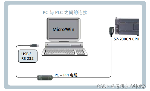
Figure 1-1 S7-200 PLC and computer connection diagram
B. S7-200 PLC communicates with other PLCs
As shown in Figure 2-1 S 7-200 PLC and other PLC connection diagram, the PLCs are connected by PROFIBUS cables, and then the Siemens network read and write commands can be used to realize the data exchange between the two PLCs.
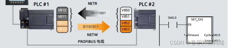
Figure 2-1 Connection diagram between S 7-200 PLC and other PLCs
C. S7-200 PLC communicates with other equipment and instruments
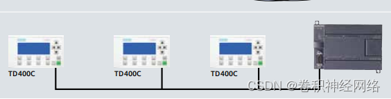
(1) The communication between S7-200 PLC and touch screen can use PPI/MPI network communication.
(2) S7-200 PLC communicates with the inverter, using the serial USS protocol for communication.

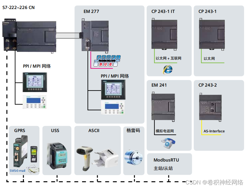
Appendix. S7-200PLC Communication Network
There are many communication methods supported by S7-200PLC. The figure below shows all the communication methods it can support.