0. Preface and purpose of writing
It is very easy to "run" the lidar, but how to use the lidar reasonably, you need to read the manual, but reading the manual is very painful for many beginners, especially when foreign manufacturers such as velodyne give a The English manual with more than 100 pages is scary to open. It is a pity that it is difficult to find the analysis on the Internet, especially the relevant information of velodyne is almost impossible to find, so it is a pity to discard it directly. The purpose of writing this article is to analyze some lidar manuals and discover the key points that need to be paid attention to or applied in engineering.
This article is based on several radars of velodyne VLS-128 (Alpha Prime), Robosense (Robosense) Ruby (128) and Hesai (Hesai) Pandar 128. Mainly, supplemented by other domestic representative lidar manuals. The content of this article is long, and it is planned to be updated in two phases: the previous phase mainly introduces velodyne 128; the next phase will continue to explain with a variety of lidar comparisons and analogies .

Table of contents
0. Preface and purpose of writing
1. Preparation and recommended study route
3.2 RPM(Revolutions Per Minute)
Summary of this issue (Part 1):
1. Preparation and recommended study route

Let's first look at a section from the Velodyne manual (pictured above). If you are just starting out, it is normal to not understand the manual. You need some engineering experience and a basic understanding of LiDar. Other users and even specially designed sensor engineers, etc., should you just persuade them to quit? Don't be afraid, think about it in turn, if we master this writing, we can be one step closer to sensor engineers! Isn't it very exciting! ! !
My recommended learning path is:
1. Reading the lidar manual requires you to have studied the classification and basic principles of lidar (for example, whether your lidar is mechanical or MEMS semi-solid-state, etc. Different lidars have different principles. Although the principles of data transmission are similar, they will hinder our in-depth understanding), you can get these resources through search engines, related books and even industry reports. Here I recommend a summary of lidar classification and principles, and find others by yourself~
Mainstream lidar classification and principle_Lingshan's Blog-CSDN Blog_Radar Types
2. At present, these mainstream radars are transmitted through Ethernet, so you need to learn the content of UDP and the use of wireshark, a common packet capture tool (most of the software manuals here or online searches are easy to get) If you have a laser radar device at hand Research on the connection, through the recording function of the visualization software provided by various manufacturers, you will record and save a pcap file for you. Learn more about what this file is for. What are the advantages? How does this package obtain point cloud data? Why? Do not directly record point cloud data;
---------------------------- After completing these two steps, you can start to read the manual in depth -------- -------------
3. (Recommended) Students who have enough energy can continue to learn ROS or ROS2. Students who will use synchronization (GNSS) at a deeper level need to read the content of the principle of GNSS timing. When you find that the English manual cannot be read, you can find a Chinese manual of a similar product (with the same principle), which will be more popular.
It is highly recommended to learn and get started with the ros part: A gentle Introduction to ROS;
You can read about GNSS time synchronization: Automatic (smart) driving | Time synchronization for industrial computer timing (PPS+GPRMC)_MendozaG's Blog-CSDN Blog
2. Reading the manual
Next, we officially enter the manual reading stage.
As mentioned above, it mainly talks about the 128-line manual of Weilideng (because it is detailed and all in English).
Velodyne 128 was a hard-to-find star product a few years ago, with a price of hundreds of thousands. According to the information in the datasheet (it does not appear in its Manual):
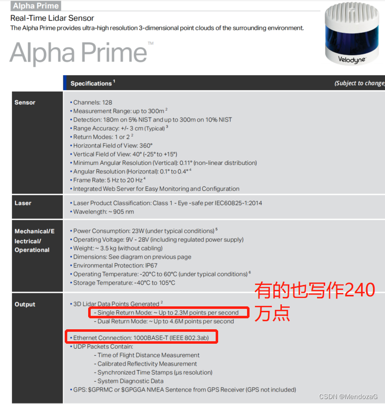
It is a laser radar around 905nm (903nm), with a point output of 2.4 million points per second, and supports gPTP (IEEE 802.3ab).
2.1 Product overview
First we get a wiring diagram:
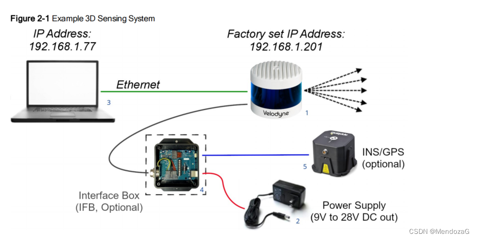
It looks the same from the picture, but notice that the lines of the laser radar ring (ring) are evenly drawn, but in fact the laser distribution is not uniform, but it is dense in the middle and sparse on both sides like Hesai and other laser radars, so Make the ROI area have more points. It is written in the manual that each laser head emits more than 18500 beams per second (18500*128=2368000 matches the 2.3 million written in the manual). The working principle is ToF.
It is also written in the manual that the Interface Boxes of 32C and 128 are not interchangeable! ! ! This is also very important, don't be lazy and connect directly when using multiple lidars, safety first! ! !

The picture above is the internal picture of the Interface Box, and tells you that the two LED lights will light up after power on, and the sensor will take about 30 seconds to start up and start scanning .
The configuration interface of velodyne is the IP of the device, the default is 192.168.1.201 (others are specific software such as little Robo of Sagitar or in the visualization software);

There are many items in the opening interface, and you may not know what the meaning is. These will be introduced later, just change the Network column to match the IP . Motor RPM refers to the frequency of click rotation (Revolutions Per Minute). The 600 on the picture refers to 10 revolutions per second, which is our usual working frequency of 10Hz. The general support is 300~1200RPM (that is, 5Hz to 20Hz , but it is not arbitrary, and generally changes in units of 60). FOV is the field of view , which is recorded in a normal scan of 360 degrees. If you only need a certain range of angles, such as some angles with blind-filling lidar, you can adjust this value without generating data. Phase lock is phase lock, and the phase is a certain value every time 1PPS comes (think about what is the use).
In terms of installation, it is recommended to install it at 0 degrees horizontally. Other installation methods may affect the life of the bearing. The equipment does not need to be equipped with shock absorption (if it is installed firmly). The design can withstand the acceleration of gravity of 500 and 3 G RMS 5 Hz to 2,000 Hz vibration . The device can read its current temperature. It is recommended to use 12V voltage, but 9~28V pure DC is also supported. The normal power consumption of the lidar is about 22W, and it does not support POE .
2.2 Echo Mode
For the echo mode (Return Type in the picture above): This lidar supports Strongest (default), Last and Dual. Laser return is a detection of reflectivity - as long as its distance is non-zero. Each beam supports up to two returns.
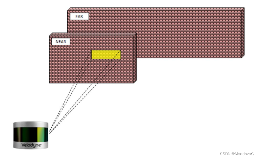
Single echo mode : There are the strongest callback mode and the last echo mode, as shown in the above picture, directly hit the wall and return, at this time the received laser is both the strongest and the last;
Multi-echo mode :
Due to beam dispersion, any one laser shot may have multiple laser returns. As a laser pulse slowly leaves the sensor, it gets progressively larger . A single pulse can be large enough to hit multiple objects, creating multiple reflections. In general, the farther away the reflection starts, the weaker it is at the detector. However, stronger results may be obtained with bright or retroreflective surfaces. After analyzing the returns of multiple channels, the lidar either records the strongest or the last echo or both (depending on the mode setting, if it is set to Strongest, it will only return the strongest reflection value, if it is set to Last, it will return Only test the last (last) return in time), through this feature you can calculate the distance from the air to the ground (such as used on drones).
dual echo mode
1. Return the strongest and last echo

As shown in the picture above, there are two targets, one far and one near ( note that the two need to be at least 1.5 meters away from the sensor to record as two targets (return value) ). Most of the laser beam hits the nearby target and some A distant target. According to the rules, if it is the strongest echo, it must return the near-end one, and if it is the last echo mode, it must return the far-end one. So what if most of the hits are far away? As shown below:
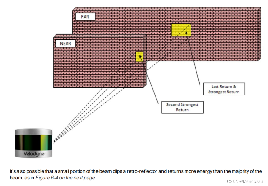
According to the picture, the far end is both the last and the strongest; but at this time Last is certain, but not necessarily the Strongest. It is still possible that even if the far end accounts for a large proportion, it is still not as strong as the near one. For example, to different On reflective materials (smaller areas are more reflective than larger areas):
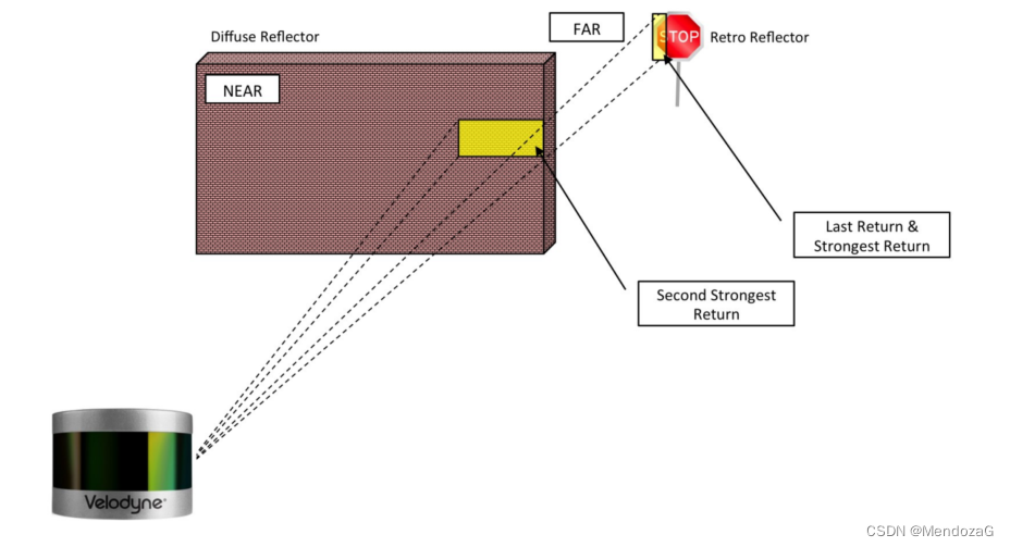
The dual return feature is often used in forestry applications where tree height measurement is required. Pictured below is the sample response when a laser pulse initially hits its trunk, penetrates it, and finally hits the ground, producing multiple returns. As can be seen from the figure below, the last return refers to the time to the ground, and the strongset return is generated at the beginning of the crossing, so the height of the tree can be measured by using two echoes (that is, the difference between the two altitudes in the figure below). Of course, recording two returns will double the amount of data.

2.3 Phase Locking
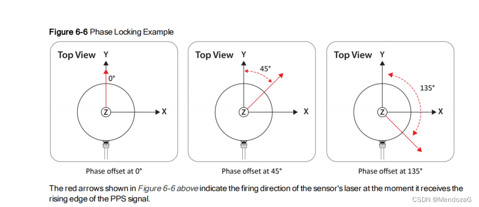
You must have thought about what to do if multiple lidars work at the same time, and what to do if other lidars receive lasers that are not emitted by them, so that the phase locking function is used to allow users to control the overlapping position of laser emissions .
Note that this function is dependent on PPS, and the phase lock function can synchronize the relative rotational positions of multiple sensors according to the PPS signal and the relative sensor orientation. For proper operation, the PPS signal must be present and locked. The working principle of phase locking is to control the laser emission according to the rising edge of the PPS signal . For genlock to work properly, the sensor's RPM setting must be set to a multiple of 60 RPM between 300 RPM and 1200 RPM (inclusive). However, for this version, due to hardware issues, the RPM is fixed at 600 (ie 10Hz is not adjustable if using PPS) .
(Not in the manual) At the same time, using this feature, we can control the phase of the lidar to calculate the synchronization.
2.4 Input of lidar

The above picture is the corresponding signal diagram of the Interface Box: pin1 and 4 are connected to the point cloud, the corresponding 2 and 3 digits are GND, pin7 is connected to PPS, pin6 is connected to Data In (such as GPRMC), and pin5 is connected to GND of GPS .
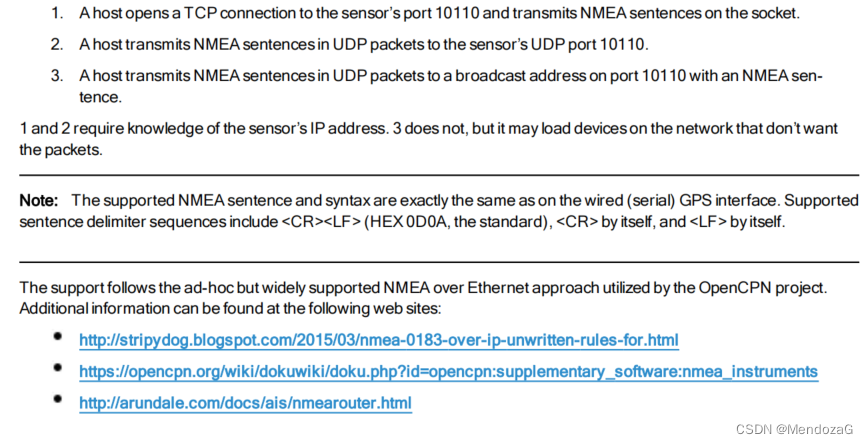
NMEA only supports GPRMC or GPGGA, other formats are not supported!
Interventional Pulse Requirements:

PPS sync pulses and GPRMC or GPGGA sentences should be received alternately without overlapping or coincidence. The PPS sync pulse width is not critical (typical length is between 10μs and 200ms). The 300 ms minimum gap after receiving an NMEA message gives the sensor enough time to extract and process the timing data from the message so that it can set the time when the leading edge of the next PPS arrives. If there is no PPS or if it does not arrive in time, the timing information extracted from the NMEA message will eventually become invalid.

The serial connection for NMEA messages is TTL serial, or more commonly known as TTL RS-232 which is not really RS-232.
It is also possible to get NMEA information from a computer instead of GPS, via a usb-to-serial adapter :

The device also supports NMEA messages over Ethernet:
3. Equipment operation
Including laser excitation (sending), process calculation: data packet rate, location information packet rate, overall packet rate, etc., and RPM.
3.1packet
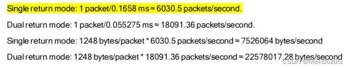
Data packet rate: In single echo mode, a data packet (packet) can accommodate up to three transmission cycles (3*55.275 microseconds = 0.1658 milliseconds), it is well understood that only one can be accommodated in double echo mode emission period (55.275 microseconds) , where 55.275 is the average amount.
In this way, the amount of packets sent per second and the amount of data per second for each mode can be calculated:
For position information, originating from the connected GPS, the rate at which position data packets arrive is more or less independent of the rate of data packets (mentioned above) ((if both position and data packets are ready to be sent by the sensor at exactly the same time, then Position packets are delayed while packets are being sent).
Location packets are usually sent at a rate of about 94 location packets per second, and the size of each packet is 554 bytes , so the data volume per second is 52076 bytes per second.
So overall: 6030.5+94=6124.5 packets (average value) per second; the amount of data generated in single echo mode is: 7578140 bytes (bytes) per second (ie 7.2271Mb per second) ; double echo mode produces 22630093.28 bytes per second ( 21.5812Mb per second ) of data.
For the single echo mode, each laser beam finally represents the data of a point, measuring distance and reflection intensity; there are 3 sequences in a packet, and there are 128 points in a transmitted sequence, so there are 128*3= in a packet 384 points; so how many points can be generated per second (this was calculated before)? Different ways are used here: 384*6030.5 (from the yellow part of the picture above) = 2315712 points per second (theoretical maximum 2.3 million) .
For the double echo mode, each return point may be 0, 1, 2 (depending on what the laser pulse reflects, 0 means no such as shooting into the sky, and one or two echoes), each packet only It can hold 1 group, so a packet only has 256 points, so according to 256*18091.36=4631388 points per second (4.63 million) .
3.2 RPM(Revolutions Per Minute)
RPM is usually set to 300~1200 (corresponding to working frequency 5Hz~20Hz), and each increment needs to be set to a multiple of 60 (60 corresponds to 1 revolution) to ensure accuracy. But the device is fixed at 600RPM (10Hz); while the sensor's firing time is always close to 55.275 us per firing sequence on average, it is still mainly the rotation speed that determines the angular resolution of the sensor. The faster it spins, the coarser the full spin speed will be measured. The slower it spins, the higher the resolution .

------------------------------------------------------------------------------------------
Summary of this issue (Part 1):
The previous issue was more principled, mainly giving the learning method and some basic principles. The specific packet content will be continued in the next issue, and other lidars will be introduced for analogy in the next issue.
----------------------------------------------------------------------------