STM32F407ZGT6 is a high-performance ARM Cortex-M4 core 32-bit microcontroller (MCU) launched by STMicroelectronics. It is a member of the STM32F4 series, with powerful processing capabilities and rich peripheral functions, suitable for various application fields.
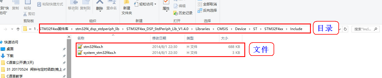
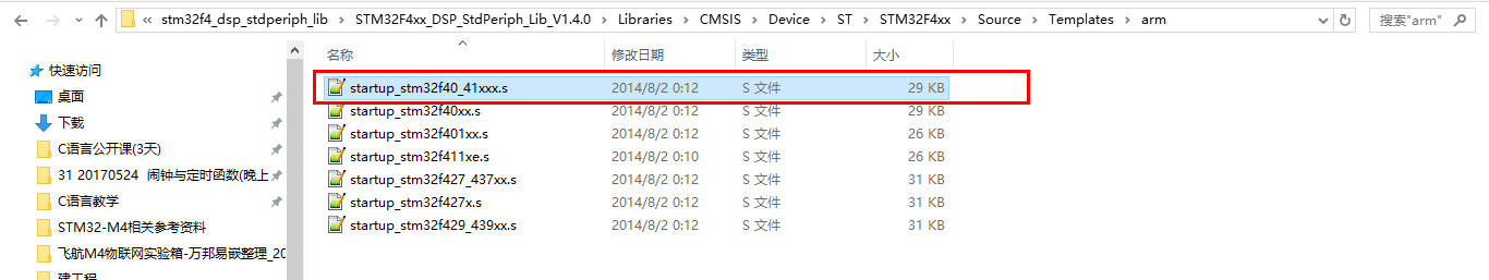
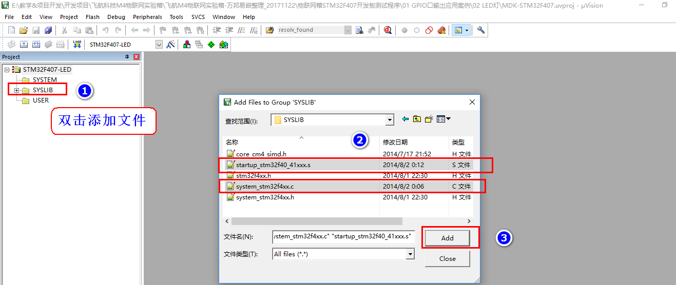
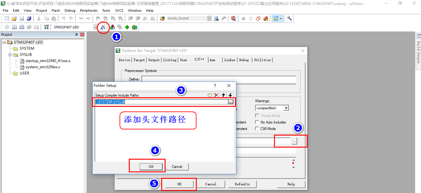
【1】F407 Dependent files required for construction projects


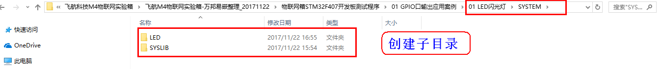
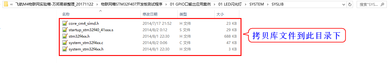
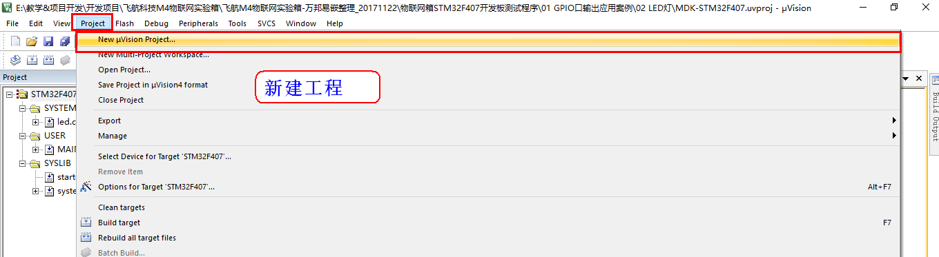
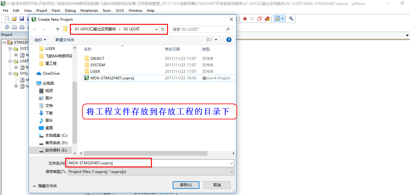
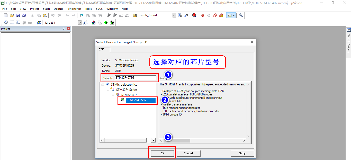
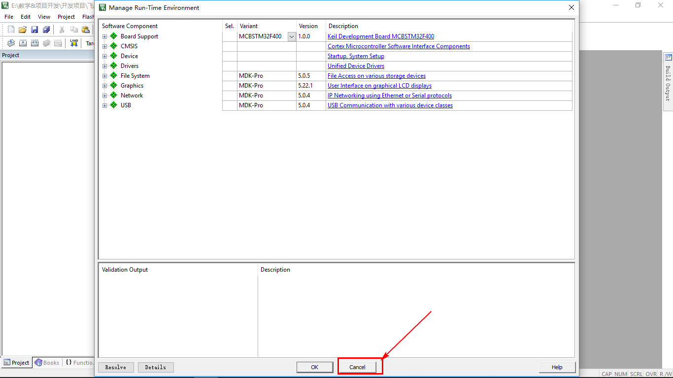
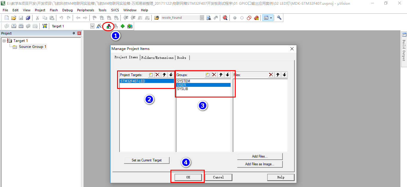
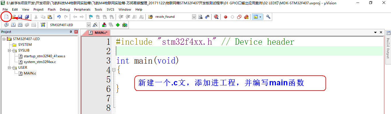
【2】 New construction
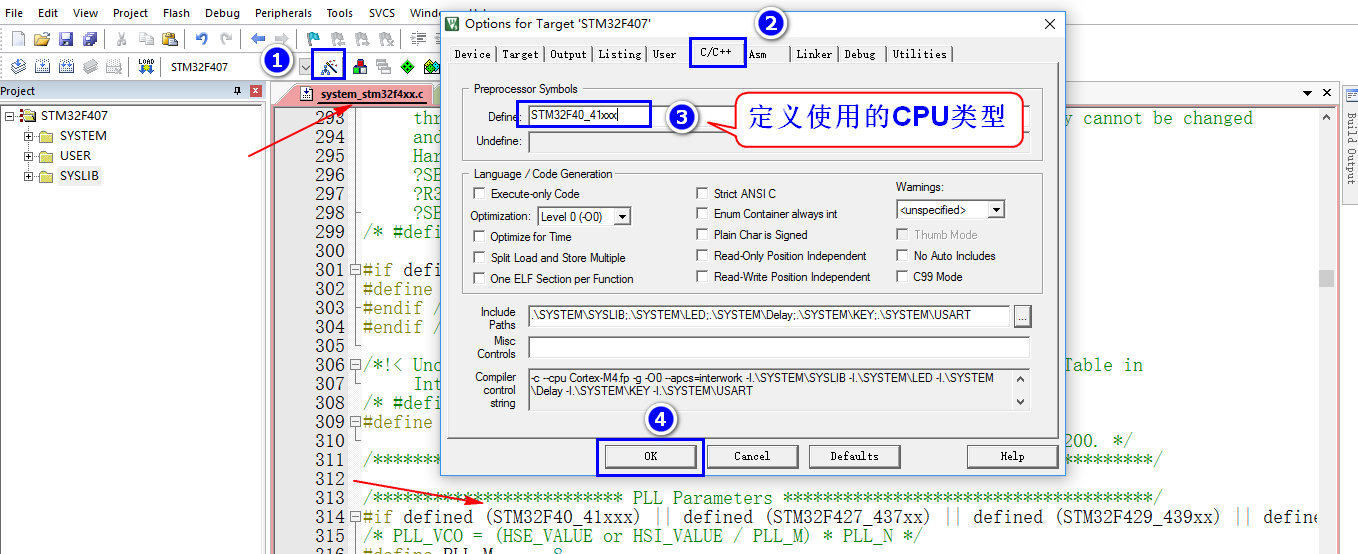
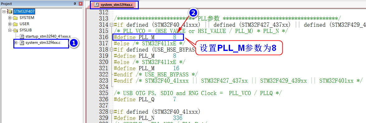
Note: The highest main frequency of STM32F4 is 168Mhz, so we generally set PLLCLK to 168Mhz (M=8, N=336, P=2), and select SYSCLK=PLLCLK through SW to get the system operating frequency of 168Mhz.
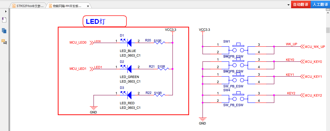
【3】Analysis of LED hardware schematic diagram
【4】Write LED driver code
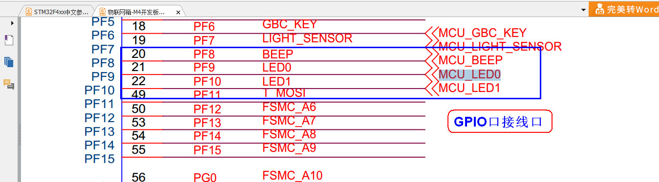
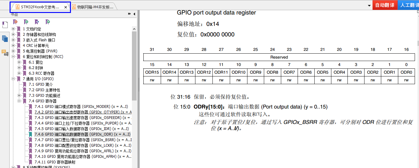
Check out the data sheet:
The code of the Led.c file is as follows:
#include "led.h"
/*
函数功能:LED初始化
硬件连接:
PF8-->BEEP  --高电平响
PF9-->LED0  --低电平亮
PF10->LED1  --低电平亮
*/
void LED_Init(void)
{


		/*1. 开时钟*/
	  RCC->AHB1ENR|=1<<5;//使能PORTF时钟

	  /*2. 配置GPIO口模式*/
	  GPIOF->MODER&=~(0x3<<8*2); //清除模式
		GPIOF->MODER|=0x1<<8*2;    //配置输出模式

		GPIOF->MODER&=~(0x3<<9*2); //清除模式
		GPIOF->MODER|=0x1<<9*2;    //配置输出模式

		GPIOF->MODER&=~(0x3<<10*2); //清除模式
		GPIOF->MODER|=0x1<<10*2;    //配置输出模式

	  /*3. 配置GPIO口输出类型*/
		GPIOF->OTYPER&=~(0x1<<8);  //0表示推挽输出
		GPIOF->OTYPER&=~(0x1<<9);  //0表示推挽输出
		GPIOF->OTYPER&=~(0x1<<10); //0表示推挽输出

		/*4. 配置GPIO口输出速度*/
		GPIOF->OSPEEDR&=~(0x3<<8*2); //清除之前配置
		GPIOF->OSPEEDR|=0x2<<8*2;    //50MHZ输出速度

		GPIOF->OSPEEDR&=~(0x3<<9*2); //清除之前配置
		GPIOF->OSPEEDR|=0x2<<9*2;    //50MHZ输出速度

		GPIOF->OSPEEDR&=~(0x3<<8*2); //清除之前配置
		GPIOF->OSPEEDR|=0x2<<10*2;   //50MHZ输出速度

		/*5. 配置GPIO口输出默认电平*/
		GPIOF->ODR|=1<<10;   	//输出1
		GPIOF->ODR|=1<<9;   	//输出1
		GPIOF->ODR&=~(1<<8);  //输出0
}
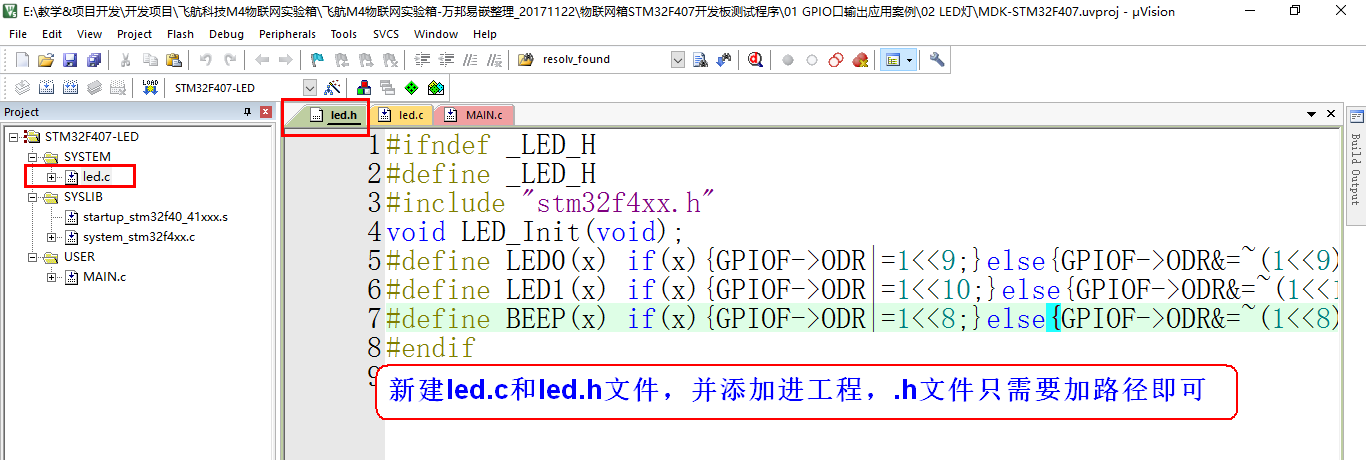
Led.h code is as follows
#ifndef _LED_H
#define _LED_H
#include "stm32f4xx.h"
void LED_Init(void);
#define LED0(x) if(x){

      GPIOF->ODR|=1<<9;}else{

      GPIOF->ODR&=~(1<<9);}
#define LED1(x) if(x){

      GPIOF->ODR|=1<<10;}else{

      GPIOF->ODR&=~(1<<10);}
#define BEEP(x) if(x){

      GPIOF->ODR|=1<<8;}else{

      GPIOF->ODR&=~(1<<8);}
#endif
Main.c code is as follows
#include "stm32f4xx.h" // Device header
#include "led.h"

void DelayMs(u32 time)
{


		u32 a,b,c;
		for(a=0;a<time;a++)
			for(b=0;b<100;b++)
				for(c=0;c<450;c++);
}

int main(void)
{


		LED_Init();
		while(1)
		{


			LED0(0);
			LED1(0);
		//	BEEP(0);
			DelayMs(1000);
			LED0(1);
			LED1(1);
			//BEEP(1);
			DelayMs(1000);
		}
}
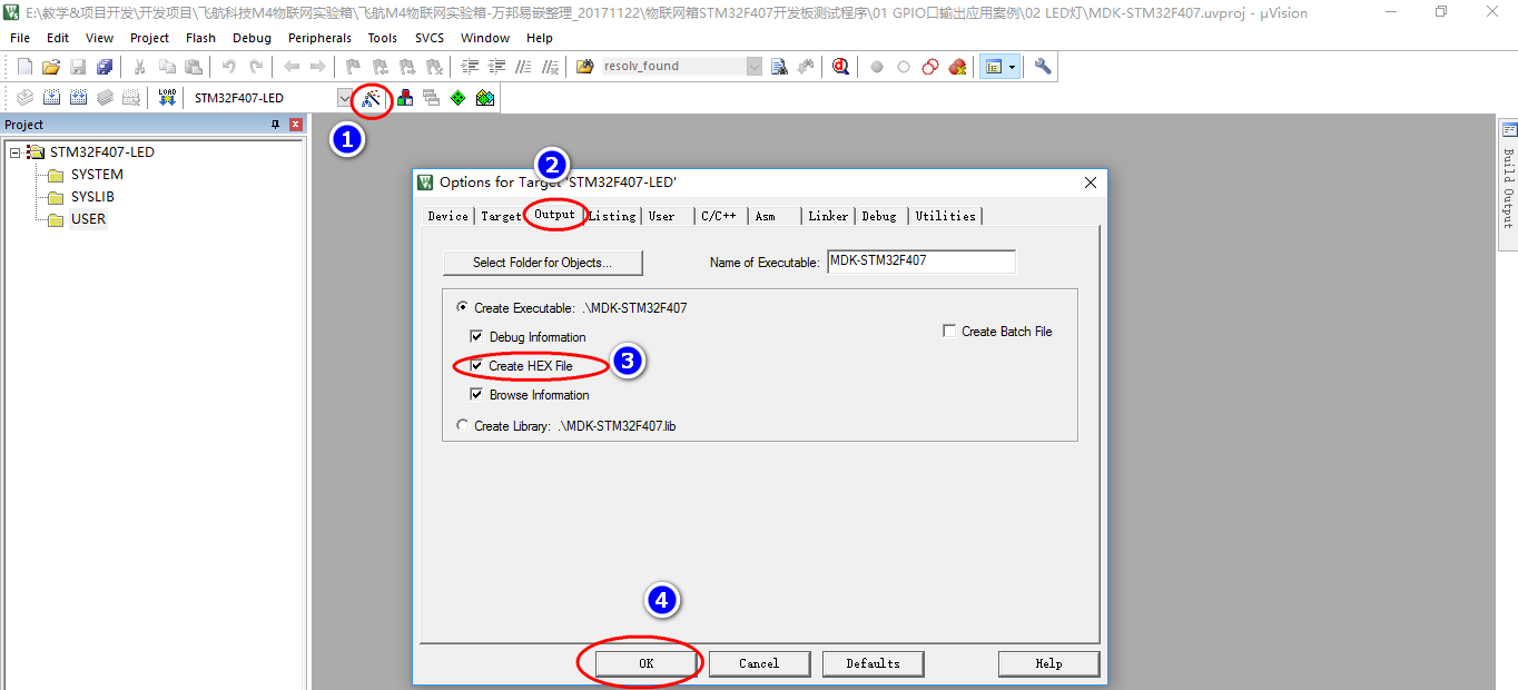
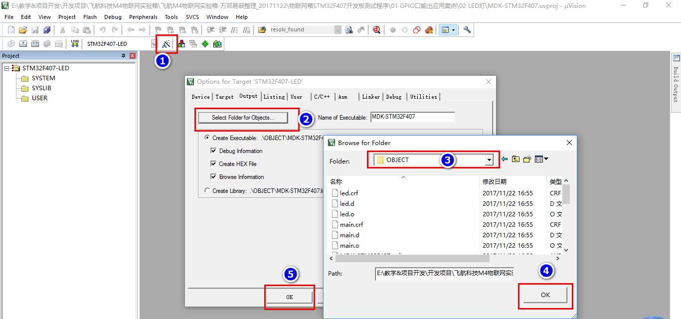
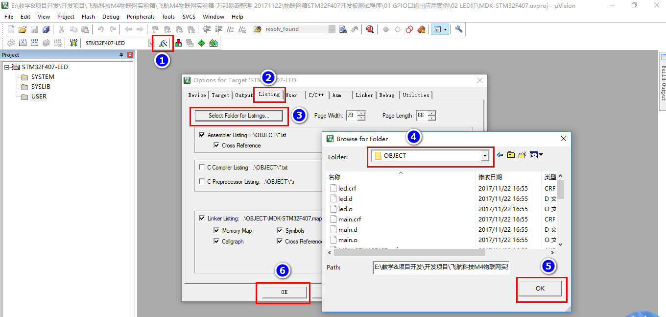
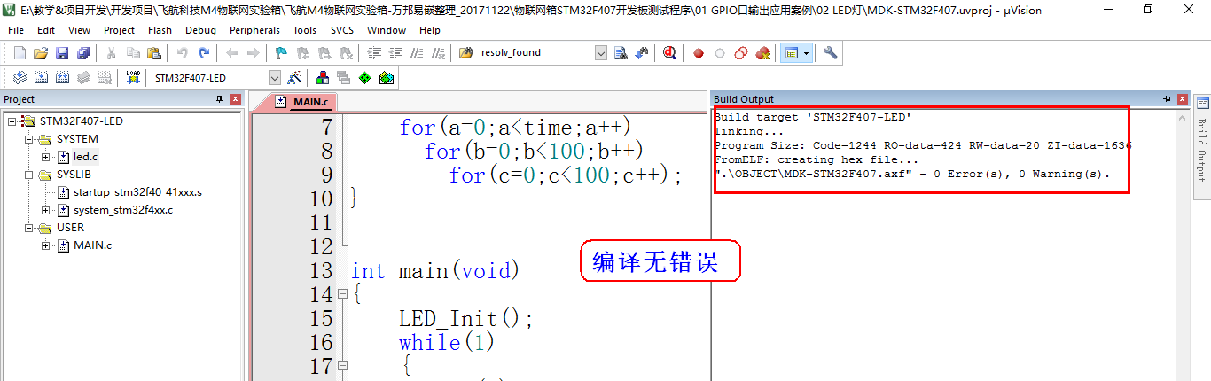
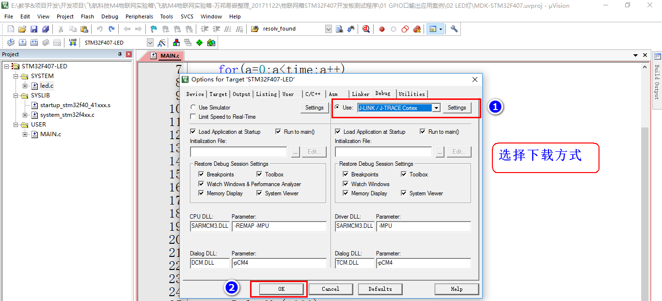
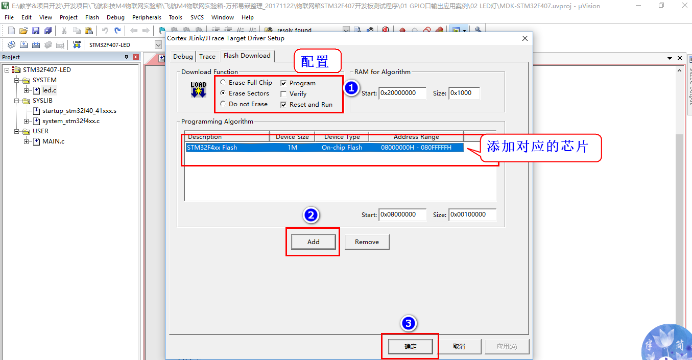
【5】Compile code configuration download
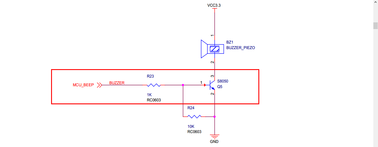
【6】Write passive buzzer driver code
Delay.c delay function code
#include "delay.h"
/*
功能  :毫秒级别的延时函数
参数  :填入延时的时间
返回值:无
说  明:频率在168MHZ情况下使用
*/
void DelayMs(u32 time)
{


	u32 a,b,c;
	for(a=0;a<time;a++)
		for(b=0;b<100;b++)
			for(c=0;c<450;c++);
}


/*
功能  :微秒级别的延时函数
参数  :填入延时的时间
返回值:无
说  明:频率在168MHZ情况下使用
*/
void DelayUs(u32 time)
{


	u32 k;
	while(time--)
	{


		k=40;
		while(k--);
	}
}
Led.c code
#include "led.h"
/*
函数功能:LED初始化
硬件连接:
PF8-->BEEP  --高电平响
PF9-->LED0  --低电平亮
PF10->LED1  --低电平亮
*/
void LED_Init(void)
{


		/*1. 开时钟*/
	  RCC->AHB1ENR|=1<<5;//使能PORTF时钟

	  /*2. 配置GPIO口模式*/
	  GPIOF->MODER&=~(0x3<<8*2); //清除模式
		GPIOF->MODER|=0x1<<8*2;    //配置输出模式

		GPIOF->MODER&=~(0x3<<9*2); //清除模式
		GPIOF->MODER|=0x1<<9*2;    //配置输出模式

		GPIOF->MODER&=~(0x3<<10*2); //清除模式
		GPIOF->MODER|=0x1<<10*2;    //配置输出模式

	  /*3. 配置GPIO口输出类型*/
		GPIOF->OTYPER&=~(0x1<<8);  //0表示推挽输出
		GPIOF->OTYPER&=~(0x1<<9);  //0表示推挽输出
		GPIOF->OTYPER&=~(0x1<<10); //0表示推挽输出

		/*4. 配置GPIO口输出速度*/
		GPIOF->OSPEEDR&=~(0x3<<8*2); //清除之前配置
		GPIOF->OSPEEDR|=0x2<<8*2;    //50MHZ输出速度

		GPIOF->OSPEEDR&=~(0x3<<9*2); //清除之前配置
		GPIOF->OSPEEDR|=0x2<<9*2;    //50MHZ输出速度

		GPIOF->OSPEEDR&=~(0x3<<8*2); //清除之前配置
		GPIOF->OSPEEDR|=0x2<<10*2;   //50MHZ输出速度

		/*5. 配置GPIO口输出默认电平*/
		GPIOF->ODR|=1<<10;   	//输出1
		GPIOF->ODR|=1<<9;   	//输出1
		GPIOF->ODR&=~(1<<8);  //输出0
}

/*
1/2000HZ=0.0005s=0.5ms=500us
1/4000HZ=0.25ms
控制蜂鸣器:产生2KHZ~5KHZ的方波即可
*/
void BEEP_Ctlrl(u8 cmd,u32 time)
{


		u8 i;
		if(cmd) //打开蜂鸣器
		{


				for(i=0;i<time;i++)
				{


						BEEP(0);
						DelayUs(250);
						BEEP(1);
						DelayUs(250);
				}
		}
		else   //关闭蜂鸣器
		{


				BEEP(0);
				for(i=0;i<time;i++)DelayUs(250);
		}
}
Mian.c main function code
#include "stm32f4xx.h" // Device header
#include "led.h"
#include "delay.h"

int main(void)
{


		u8 i;
		LED_Init();
		while(1)
		{


				 i=!i;
				 BEEP_Ctlrl(i,200);
		}
}