https://zhuanlan.zhihu.com/p/520060653
This article is based on the following hardware and software assumptions:
Architecture: AARCH64
Software: Uboot 2021.10-rc1
1 Uboot overall process
Looking back at the atf we introduced earlier, its basic startup process is: BL1 – BL2 – BL31 – BL32 – BL33 (uboot), that is, start uboot after the startup of bl32 is completed, and uboot is used as the last level image in the startup chain for Start the final os. Atf is introduced by arm to enhance system security, and only supports trusted firmware of armv7 and armv8 architectures. And uboot is a general embedded system boot program, which can support a variety of processor architectures including arm, such as mips, riscv, powerpc and x86, etc., and its history is longer than atf. Therefore, by default, uboot does not need to be started together with atf, but itself is designed to support a complete multi-level boot chain, which is designed to include up to three stages of spl, tpl, and uboot. Next, let's take a look at some combinations of these stages through some typical startup processes.
1.1 Start without atf
spl is called secondary program loader, which is generally loaded by bootrom in the startup chain as the second-level boot image (bl2). It is mainly used to complete the initialization of some basic modules and ddr, and load the next-level image uboot. Since spl needs to be loaded into sram for execution, for some systems with relatively small sram size, it may not be possible to fit the entire spl image, tpl is introduced to solve this problem. After adding tpl, the function of spl can be further divided into two parts. For example, spl contains ddr initialization related codes, and tpl contains image loading related drivers, thereby reducing the size of spl image. At this time, the startup process can be designed as follows:
bootrom --> spl (init ddr) --> bootrom --> tpl (load and run uboot) --> uboot
Its schematic diagram is as follows:
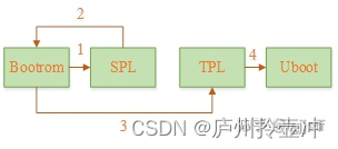
In this process, spl mainly completes ddr initialization. Since it does not have a driver related to image loading, it needs to jump back to bootrom after the execution is completed, and the bootrom completes the loading of tpl (similar to jumping back to bl1 after bl2 loading in ATF) ), and the final uboot loading is done by tpl. Since the main process of tpl is almost the same as that of spl, and most systems do not need tpl, our next discussion will mainly focus on the two stages of spl and uboot
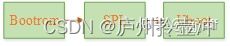
If tpl is not required, the typical startup process of uboot can be simplified as follows (this is also the most common way of running uboot):
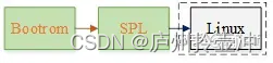
Of course, for some scenarios that require high startup speed, the startup process can be further simplified. For example, it can be designed as the following method of skipping uboot and directly starting the operating system through spl. At this time, the startup process is as follows:
1.2 Combination of Atf and uboot to start
If the system needs to support both secure and non-secure execution states, it must be started from the secure space, and after the startup is complete, the normal os needs to process requests related to secure space services through the secure monitor (bl31). At this time, atf will be very convenient to help us achieve this goal. This is also the startup method we have introduced in the first article. Let us repost its loading and startup flow chart below:
(1) The typical image loading process of atf starting uboot
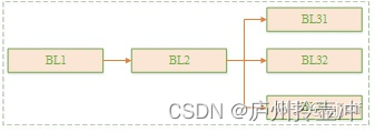
(2) The typical image jump process of atf starting uboot
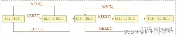
In the above process, bl32 is optional. If trust os is not supported, the process can be cut out. Typically, bl33 is uboot, and bl2 can be implemented with atf or replaced with spl
2 uboot initialization
Except for some parts distinguished by compilation options, and the specific implementation of the board_init_f and board_init_r functions, the initialization process of uboot and spl is exactly the same. The spl initialization process has been introduced in detail in another article <spl startup analysis>: talk about SOC startup (7) SPL startup analysis
Therefore, the text will mainly introduce the content of uboot's unique part, and other codes will only be briefly analyzed. By convention, we still give the uboot initialization flow chart first:
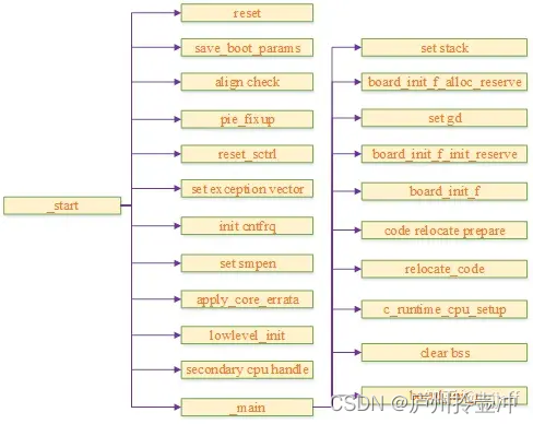
The process mainly includes the following parts:
(1) save_boot_params saves the parameters passed in from the upper-level image, and this function is defined by the platform itself
(2) If pie is supported, check whether the code segment is 4k aligned (because due to the limitation of the operand length in the instruction set, the addressing range of instructions such as adr needs to be 4k aligned)
(3) pie_fixup relocates the contents of the .rela.dyn segment related to the global address for pie
(4) reset_sctrl determines whether to reset the sctlr register according to the configuration
(5) Set the exception vector table for uboot. The spl and uboot exception vector table settings are different as follows:
- When spl sets the configuration option CONFIG_ARMV8_SPL_EXCEPTION_VECTORS, it will set the exception vector table for it, otherwise it will not set the exception vector table for it
- By default, uboot will set the exception vector table
The exception vector table format of armv8 is as follows:
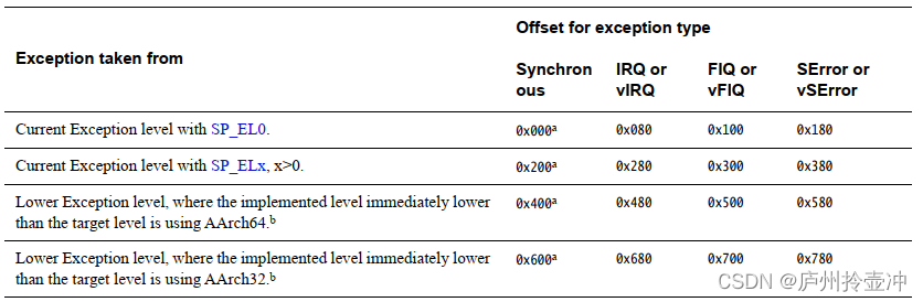
That is, armv8 will jump to different interrupt vectors according to the exception level that the CPU is running when the interrupt is triggered, the type of stack register used, and the running state. Since spl and uboot will not execute code with a lower exception level than the current one during the startup process, it is only necessary to implement 8 exception vectors under the current exception level. Its corresponding vector table is defined in arch/arm/cpu/armv8/exceptions.S.
Since according to different configurations, spl or uboot can run at el1 - el3 exception level, it is necessary to select the exception vector table base address register according to the current actual exception level
(6) If the COUNTER_FREQUENCY option is configured, determine whether to set the frequency of the system counter of the cpu according to the abnormal level currently running. Since the frequency of the system counter is shared by all exception levels, in order to ensure that the frequency is not modified arbitrarily, it is agreed that this register is only allowed to be modified when running at the highest exception level
(7) If the configuration option CONFIG_ARMV8_SET_SMPEN is set, set S3_1_c15_c2_1 to enable data consistency between cpus
(8) apply_core_errata is used to process the errata of the cpu
(9) lowlevel_init process can refer to spl start analysis
(10) The secondary cpu processing flow will be introduced in Section 2.1
(11) The definition of _main is located in arch/arm/lib/crt0_64.S, and its process is shown in Section 2.2
2.1 Process flow from cpu
In the smp system, only the master cpu performs a complete boot process, and the other slave cpus need to be set to a specific state at the beginning of the boot. , after the master cpu finishes starting the system, wake up the slave cpu to execute from the given address. There are two methods of armv8 booting from the cpu, psci and spintable, among which the psci method needs to be processed by bl31, which we will introduce later. Here we see how uboot handles the spintable method. The following is its source code:
#if defined(CONFIG_ARMV8_SPIN_TABLE) && !defined(CONFIG_SPL_BUILD)          (1)
	branch_if_master x0, x1, master_cpu                                 (2)
	b	spin_table_secondary_jump                                   (3)
#elif defined(CONFIG_ARMV8_MULTIENTRY)                                      (4)
	branch_if_master x0, x1, master_cpu                                 (5)
slave_cpu:
	wfe                                                                 (6)
	ldr	x1, =CPU_RELEASE_ADDR                                       (7)
	ldr	x0, [x1]
	cbz	x0, slave_cpu                                               (8)
	br	x0                                                          (9)
#endif
master_cpu:
	bl	_main
(1) If the current slave cpu is the spin table startup mode, and the current execution is uboot. Then the slave CPU will enter the spin state through wfe, and wait for the kernel to fill in its startup entry function to the given address. The process is as follows:
ENTRY(spin_table_secondary_jump)
.globl spin_table_reserve_begin
spin_table_reserve_begin:
0:      wfe                                                  (1)
        ldr     x0, spin_table_cpu_release_addr              (2)
        cbz     x0, 0b                                       (3)
        br      x0                                           (4)
.globl spin_table_cpu_release_addr
        .align  3
spin_table_cpu_release_addr:                                 (5)
        .quad   0
.globl spin_table_reserve_end
spin_table_reserve_end:
ENDPROC(spin_table_secondary_jump)
- Enter wfe sleep mode from cpu
- If the cpu is awakened, read the value of spin_table_cpu_release_addr
- If the kernel does not write the entry function it starts to this address, it will continue to return to sleep
- Otherwise, jump to the read entry to start the boot process from the cpu
- Define the memory address that saves the entry function from the cpu, and this address will be filled in the properties of the spintable node of the device tree when uboot starts. When the kernel starts the slave cpu, it completes its startup by writing the entry function to the resolved address and waking up the secondary cpu
(2) If the current CPU is the main CPU, continue the cold start process
(3) If the current cpu is a slave cpu, enter the spin mode of step 1
(4) If the spintable is not configured, the slave CPU needs to spin at a system predefined address, and wait for uboot to fill in the entry function to the address at the right time
(5) If the current CPU is the main CPU, continue the cold start process
(6 - 9) The process is similar to the spintable method, and the cpu enters the sleep mode through wfe, and checks whether the value of the given address has been filled after waking up. If it is filled in, it will jump to the entry function to start executing, otherwise it will continue to enter the sleep mode.
2.2 _main process analysis
2.2.1 GD and memory planning before uboot relocation
Before entering the c language, we need to prepare the operating environment for it and make a memory plan. In addition to the stack and heap memory, we also need to allocate memory space for the gd structure. gd is a global_data type global variable in uboot, which contains many global related parameters, which provides convenience for the transfer and sharing of parameters between modules. Since the variable needs to be prepared before jumping to the c process, the heap manager has not been initialized at this time, so its memory needs to be allocated through manual management. The following is the code related to uboot memory planning:
#if defined(CONFIG_TPL_BUILD) && defined(CONFIG_TPL_NEEDS_SEPARATE_STACK)
	ldr	x0, =(CONFIG_TPL_STACK)
#elif defined(CONFIG_SPL_BUILD) && defined(CONFIG_SPL_STACK)
	ldr	x0, =(CONFIG_SPL_STACK)
#elif defined(CONFIG_INIT_SP_RELATIVE)
#if CONFIG_POSITION_INDEPENDENT
	adrp	x0, __bss_start
	add	x0, x0, #:lo12:__bss_start
#else
	adr	x0, __bss_start
#endif
	add	x0, x0, #CONFIG_SYS_INIT_SP_BSS_OFFSET
#else
	ldr	x0, =(CONFIG_SYS_INIT_SP_ADDR)                         (1)
#endif
	bic	sp, x0, #0xf                                           (2)
	mov	x0, sp
	bl	board_init_f_alloc_reserve                             (3)
	mov	sp, x0                                                 (4)
	mov	x18, x0                                                (5)
	bl	board_init_f_init_reserve                              (6)
(1) The above part obtains the initial stack address of uboot according to different configuration situations
(2) In order to follow the ABI specification, the stack address needs to be 16-byte aligned. This instruction aligns the address and sets it in the stack pointer register to set the running stack for the system.
(3) This function allocates memory for gd and early malloc, and its code is as follows:
ulong board_init_f_alloc_reserve(ulong top)
{


#if CONFIG_VAL(SYS_MALLOC_F_LEN)
        top -= CONFIG_VAL(SYS_MALLOC_F_LEN);                         (a)
#endif
        top = rounddown(top-sizeof(struct global_data), 16);         (b)
        return top;
}
a Reserve memory for the early heap manager
b Reserve memory for gd
(4) Set the reserved memory address as the new stack address. At this time, the addresses of each part are as follows:
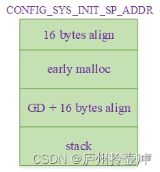
(5) Save the gd address to the x18 register, which can be used for subsequent acquisition of the gd pointer
(6) This process is mainly used to initialize gd and set the base address of the early malloc heap manager. The code is as follows:
void board_init_f_init_reserve(ulong base)
{


        struct global_data *gd_ptr;

        gd_ptr = (struct global_data *)base;
        memset(gd_ptr, '\0', sizeof(*gd));                                       (a)
#if !defined(CONFIG_ARM)
        arch_setup_gd(gd_ptr);                                                   (b)
#endif
        if (CONFIG_IS_ENABLED(SYS_REPORT_STACK_F_USAGE))
                board_init_f_init_stack_protection_addr(base);                   (c)
        base += roundup(sizeof(struct global_data), 16);
#if CONFIG_VAL(SYS_MALLOC_F_LEN)
        gd->malloc_base = base;                                                  (d)
#endif
        if (CONFIG_IS_ENABLED(SYS_REPORT_STACK_F_USAGE))
                board_init_f_init_stack_protection();                            (e)
}
a Get the gd pointer and clear the gd structure memory
b This function is used to obtain the gd pointer of the non-arm architecture, and the armv8 architecture obtains the gd pointer through the previously set x18 register, which is defined as follows (arch/arm/include/asm/global_data.h):
  #ifdef CONFIG_ARM64
      #define DECLARE_GLOBAL_DATA_PTR         register volatile gd_t *gd asm ("x18")
      #else
      #define DECLARE_GLOBAL_DATA_PTR         register volatile gd_t *gd asm ("r9")
      #endif
c This function is used to obtain the address of the stack overflow detection
d Set the base address of early malloc
e Initialize the canary value of stack overflow detection, which is set to SYS_STACK_F_CHECK_BYTE
2.2.2 uboot relocation
The general startup process will initialize ddr by spl, and then load uboot into ddr to run. But this is not necessary. In fact, uboot itself can also be used as a bl1 or bl2 boot image. At this time, the initial boot location of uboot is not located in ddr (such as norflash). Since the execution speed of norflash is much slower than that of ddr, it needs to be moved to ddr after ddr initialization is completed, and then switched to a new location to continue execution. This process is called uboot relocation
2.2.2.1 Prerequisites for Relocation
Uboot relocation relies on position-independent code technology, so the following support needs to be added when compiling and relocating:
(1) Add -fpie option when compiling
(2) Add the -pie option when linking, which makes the linker generate fixup tables for the .rel.dyn and .dynsym sections.
(3) Add .rel.dyn and .dynsym segment definitions to the link script, and provide symbolic information for the relocation code to access the data of these segments
(4) During the relocation process, the data in the .rel.dyn and .dynsym segments need to be fixed according to the new address
2.2.2.2 Basic flow of relocation
Since the kernel needs to start running from the low address of the memory, in order to prevent the loading address of the three-piece kernel (kernel, dtb, and ramdisk) from overlapping with the uboot running address, the relocation address of uboot needs to be set near the top of the memory. At the same time, we also need to reserve some memory space (such as page table space, framebuffer, etc.) for some specific modules. The following figure is the memory layout after relocation planned by uboot:
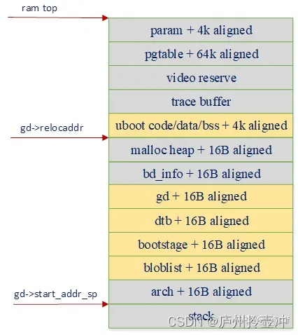
The orange parts in the figure all need to perform relocation operations, such as uboot's code segment, data segment, gd, device tree, etc., all of which need to be used in the board_init_r stage. For the relocation of pure data such as gd and dtb, it is only necessary to copy the data to a new address and switch its base address pointer to the new address. But for the relocation of the code segment, we also need to consider the following issues:
(1) The position-independent code needs to adjust the .rel.dyn and .dynsym sections
(2) The stack pointer needs to be switched to a new location
(3) How to complete the smooth switching of PC after the relocation is completed
The following is the source code related to armv8 code relocation preparation, which is located in arch/arm/lib/crt0_64.S:
#if !defined(CONFIG_SPL_BUILD)
	ldr	x0, [x18, #GD_START_ADDR_SP]                         (1)
	bic	sp, x0, #0xf                                         (2)
	ldr	x18, [x18, #GD_NEW_GD]                               (3)
	adr	lr, relocation_return                                (4)
#if CONFIG_POSITION_INDEPENDENT
	adrp	x0, _start
	add	x0, x0, #:lo12:_start
	ldr	x9, _TEXT_BASE
	sub	x9, x9, x0
	add	lr, lr, x9                                            (5)
#if defined(CONFIG_SYS_RELOC_GD_ENV_ADDR)
	ldr	x0, [x18, #GD_ENV_ADDR]
	add	x0, x0, x9
	str	x0, [x18, #GD_ENV_ADDR]                               (6)
#endif
#endif
	ldr	x9, [x18, #GD_RELOC_OFF]
	add	lr, lr, x9                                            (7)
	ldr	x0, [x18, #GD_RELOCADDR]
	b	relocate_code                                         (8)
relocation_return:
(1) Obtain the new stack pointer address
(2) Set up a new stack
(3) Set new gd address to x18 to switch gd to new location
(4) Load the relocation return location into lr. During the relocation process, this address will be adjusted to the corresponding location of the new code segment. And after the relocation is completed, jump to the address for execution, thus completing the switching of the code from the old location to the new location
(5) If the position-independent option CONFIG_POSITION_INDEPENDENT is defined, calculate its offset value and use the offset value to adjust the value of lr
(6) If the environment variable relocation option CONFIG_SYS_RELOC_GD_ENV_ADDR is defined, adjust the address of the environment variable to a new location
(7) Adjust the position of lr according to the relocation offset
(8) Enter the actual code relocation process
The code relocation process of armv8 is located in arch/arm/lib/relocate_64.S, and its code is as follows:
ENTRY(relocate_code)
	stp	x29, x30, [sp, #-32]!
	mov	x29, sp
	str	x0, [sp, #16]                           (1)

	adrp	x1, __image_copy_start
	add	x1, x1, :lo12:__image_copy_start
	subs	x9, x0, x1
	b.eq	relocate_done	                        (2)
	ldr	x1, _TEXT_BASE
	subs	x9, x0, x1                              (3)

	adrp	x1, __image_copy_start
	add	x1, x1, :lo12:__image_copy_start
	adrp	x2, __image_copy_end
	add	x2, x2, :lo12:__image_copy_end          (4)
copy_loop:                                              (5)
	ldp	x10, x11, [x1], #16
	stp	x10, x11, [x0], #16
	cmp	x1, x2
	b.lo	copy_loop
	str	x0, [sp, #24]                           (6)

	adrp	x2, __rel_dyn_start	                (7)
	add	x2, x2, :lo12:__rel_dyn_start
	adrp	x3, __rel_dyn_end
	add	x3, x3, :lo12:__rel_dyn_end
fixloop:
	ldp	x0, x1, [x2], #16
	ldr	x4, [x2], #8
	and	x1, x1, #0xffffffff
	cmp	x1, #R_AARCH64_RELATIVE
	bne	fixnext

	add	x0, x0, x9
	add	x4, x4, x9
	str	x4, [x0]
fixnext:
	cmp	x2, x3
	b.lo	fixloop

relocate_done:
	switch_el x1, 3f, 2f, 1f                       (8)
	bl	hang
3:	mrs	x0, sctlr_el3
	b	0f
2:	mrs	x0, sctlr_el2
	b	0f
1:	mrs	x0, sctlr_el1
0:	tbz	w0, #2, 5f                             (9)
	tbz	w0, #12, 4f                            (10)
	ic	iallu
	isb	sy
4:	ldp	x0, x1, [sp, #16]
	bl	__asm_flush_dcache_range
	bl     __asm_flush_l3_dcache
5:	ldp	x29, x30, [sp],#32                     (11)
	Ret                                            (12)
ENDPROC(relocate_code)
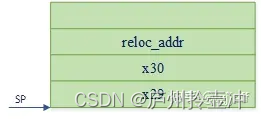
(1) Construct a stack frame, which includes lr register x30, fp register x29 and function input parameter x0, where x0 is the starting destination address of relocation. The contents of the stack frame after this process are as follows:
(2) Calculate the offset between the image running address and the destination address. If they are equal, then obviously there is no need to perform relocation, and this process can be skipped directly
(3) Calculate the offset between the mirror link address and the destination address
(4) Read the start address and end address of the image running address
(5) Copy the image from the running address to the relocation destination address
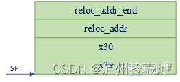
(6) Push the relocation end address into the stack, and the contents of the stack frame after being pushed into the stack are as follows:
(7) Position-independent code-related processing
(8) According to the currently executed exception level, jump to the corresponding position to read the contents of the sctlr register
(9 - 10) Since the pc will jump to a new location for execution after relocation, if the cache is enabled, it is obvious that the instruction loaded into the cache before relocation is still the old address. If you jump directly at this time, the The content in the cache is wrong. Therefore, the content already loaded in the cache must be invalidated
(11) Restore the contents of x29 and x30 (lr) from the stack frame. Now everything is ready, we only owe Dongfeng, we just need to jump to the new address to execute through the ret command
(12) After a slow and long distance, let's continue running happily at the new location
2.2.2.3 The impact of relocation on debugging
We know that the debugger will look up the symbol table through the link address by default, but after the code is relocated, its running address is inconsistent with the link address. If no adjustment is made at this time, the debugging The compiler will not be able to use the symbol table. Let's take debugging uboot under qemu as an example to introduce how to solve this problem.
(1) qemu starts uboot
qemu-system-aarch64 \
     -M  virt \
     -cpu cortex-a53 \
     -smp 2 \
     -m 2048M \
     -kernel ~/work/u-boot/u-boot \
         -nographic -s -S
(2) Start the gdb debugger
aarch64-linux-gnu-gdb ~/work/u-boot/u-boot
(3) Connect to uboot remotely
target remote :1234
(4) Discard the old symbol table
symbol-file
(5) Add the symbol table to the location after relocation, assuming its address is 0xbff8a000, the command is as follows:
add-symbol-file u-boot 0xbff8a000
(6) After that, you can continue debugging in the normal way, such as setting breakpoints, reading symbol values, etc.
(7) If you do not know the relocation address of uboot, you can set a breakpoint at the position after the calculation of the reloc address is completed, and read relocaddr at the breakpoint. It works as follows:
a Set a breakpoint
b setup_reloc
b Continue to run until the breakpoint is triggered, then read the value of relocaddr from gd
 (gdb) p /x gd->relocaddr
   $2 = 0xbff8a000
c Discard the old symbol table according to the previous steps and load the symbol table to the new address 0xbff8a000
d Set a breakpoint after relocation and continue execution