This article is based on the following hardware and software assumptions:
Architecture: AARCH64
Software: Uboot 2021.10-rc1
1 Main features supported by Uboot
After the initialization is complete, uboot will provide the user with a command line interactive interface through which the user can execute the commands defined by uboot to view the system status, set environment variables and system parameters, etc. In order to facilitate the management of hardware and drivers, uboot also introduces device tree and driver model features similar to the linux kernel. Of course, in order to increase the configurability, debuggability, and traceability of the system, it also supports functions such as environment variables, log management, bootstage statistics, and simple ftrace. Below we will give a brief introduction to these features
1.1 Device tree
The device tree is a mechanism to describe the SOC attributes through the dts file, and separate the specific configuration information of the device from the driver, so as to use one code to adapt to multiple devices. The dts file contains a series of nodes and attributes in a hierarchical structure, which can be compiled into a binary dtb file suitable for device parsing by the dtc compiler. The use of the uboot device tree includes the following processes: adding a dts file for the target board, selecting a dtb file used at runtime, and enabling the device tree. The following is a detailed introduction:
(1) How to add a dts file for the target board
In the arch//dts directory, add a xxx.dts file, which can be copied from the kernel, or select a dts of other target boards in the uboot dts directory as the basis, and then modify it according to actual needs. After the modification is complete, add compilation options to arch/arm/dts/Makefile:
dtb-$(CONFIG_yyy) +=xxx.dtb
Where yyy is the target board using the dts
(2) How to select the dts file for the target board
The uboot device tree file is located in the arch//dts directory. You can select a default dts file for the target board through the following options:
CONFIG_DEFAULT_DEVICE_TREE="xxx”
This is because unlike the kernel, the final image of uboot will be packaged with dtb in an image file, so the final dtb to be used needs to be known during the compilation process. The relationship between uboot image and dtb will be introduced in detail later
(3) Specify dts by compiling the command
Sometimes you want to use a dts that is not specified by default when compiling, you can specify a new dts file by adding DEVICE_TREE=zzz to the compilation command, the example is as follows:
make DEVICE_TREE=zzz
(4) How to enable the device tree
Device tree support can be enabled by configuring the CONFIG_OF_CONTROL option
Uboot and dtb can have the following packaging combinations:
(1) If the CONFIG_OF_EMBED option is defined, a separate segment beginning with __dtb_dt_begin will be specified for dtb when linking, and the contents of dtb will be directly linked to the uboot.bin image. The official recommendation is that this method should only be used in the development and debugging stages, not in the production stage
(2) If the CONFIG_OF_SEPARATE option is defined, dtb will be compiled into a u-boot.dtb file, and the uboot original image will be compiled into a u-boot-nodtb.bin file, and they will be connected as the final uboot by the following command. bin file:
cat u-boot-nodtb.bin u-boot.dtb >uboot.bin
1.2 Drive model DM
The Uboot driver model is similar to the linux device model, which can be used to separate the device from the driver. On the one hand, it can provide a unified operation interface for the same type of equipment, and on the other hand, it can provide a standard registration interface for the driver, so as to improve the reusability and portability of the code. At the same time, the driver model organizes all devices in uboot through a tree structure, which provides convenience for the system to manage devices uniformly.
1.2.1 Structure of the driving model
The driver model is mainly used to manage the drivers and devices in the system, and uboot provides them with the following description structure:
(1) driver structure
The driver structure is used to represent a driver, which is defined as follows:
struct driver {


	char *name;
	enum uclass_id id;
	const struct udevice_id *of_match;
	int (*bind)(struct udevice *dev);
	int (*probe)(struct udevice *dev);
	int (*remove)(struct udevice *dev);
	int (*unbind)(struct udevice *dev);
	int (*of_to_plat)(struct udevice *dev);
	int (*child_post_bind)(struct udevice *dev);
	int (*child_pre_probe)(struct udevice *dev);
	int (*child_post_remove)(struct udevice *dev);
	int priv_auto;
	int plat_auto;
	int per_child_auto;
	int per_child_plat_auto;
	const void *ops;	/* driver-specific operations */
	uint32_t flags;
#if CONFIG_IS_ENABLED(ACPIGEN)
	struct acpi_ops *acpi_ops;
#endif
}
Drivers can be registered to the system through the following interfaces:
#define U_BOOT_DRIVER(__name)						\
	ll_entry_declare(struct driver, __name, driver)
其中ll_entry_declare的定义如下:
#define ll_entry_declare(_type, _name, _list)				\
	_type _u_boot_list_2_##_list##_2_##_name __aligned(4)		\
			__attribute__((unused))				\
			__section(".u_boot_list_2_"#_list"_2_"#_name)
That is, it will define a _u_boot_list_2_driver_2_# name variable of type struct driver , which needs to be placed in the .u_boot_list_2_driver_2 #_name segment when linking . Let's take a look at how these sections are stored in the link script. The following is the definition in the armv8 architecture link script arch/arm/cpu/armv8/u-boot.lds.
 .u_boot_list : {


     KEEP(*(SORT(.u_boot_list*)));
 }
It can be seen from the definition that these sections starting with .u_boot_list will be saved together, and they will be sorted according to the name of the section before saving. This is mainly for the convenience of traversing these structures. If we need to traverse all registered drivers, the starting address of the driver structure and the total number of drivers can be obtained through the following code.
struct driver *drv =
			ll_entry_start(struct driver, driver);         (1-1)
int n_ents = ll_entry_count(struct driver, driver);                    (1-2)
(1-1) Obtain the starting address of the registered driver
(1-2) Get the number of registered drivers
The definitions of ll_entry_start and ll_entry_coun are as follows:
#define ll_entry_start(_type, _list)					\
({

      									\
	static char start[0] __aligned(CONFIG_LINKER_LIST_ALIGN)	\
		__attribute__((unused))					\
		__section(".u_boot_list_2_"#_list"_1");			\              (1-3)
	(_type *)&start;						\
})

#define ll_entry_end(_type, _list)					\
({

      									\
	static char end[0] __aligned(4) __attribute__((unused))		\
		__section(".u_boot_list_2_"#_list"_3");			\               (1-4)
	(_type *)&end;							\
})

#define ll_entry_count(_type, _list)					\
	({

      								\
		_type *start = ll_entry_start(_type, _list);		\
		_type *end = ll_entry_end(_type, _list);		\
		unsigned int _ll_result = end - start;			\               (1-5)
		_ll_result;						\
	})
(1-3) Define a section of .u_boot_list_2_“#_list”_1. If you need to traverse the driver, the name of the section is .u_boot_list_2_driver_1, that is, it is located before all actual driver sections
(1-4) Define a section of .u_boot_list_2_“#_list”_3. If you need to traverse the driver, the name of the section is .u_boot_list_2_driver_3, that is, it is located after all the actual driver sections
(1-5) Through the above two labels, you can easily obtain the start and end addresses of the driver and calculate the total number of registered drivers
Finally, we give the layout of the .u_boot_list_2 type section in memory:

(2) uclass_driver structure
The uclass_driver structure is used to represent a uclass driver, which is defined as follows:
struct uclass_driver {


	const char *name;
	enum uclass_id id;
	int (*post_bind)(struct udevice *dev);
	int (*pre_unbind)(struct udevice *dev);
	int (*pre_probe)(struct udevice *dev);
	int (*post_probe)(struct udevice *dev);
	int (*pre_remove)(struct udevice *dev);
	int (*child_post_bind)(struct udevice *dev);
	int (*child_pre_probe)(struct udevice *dev);
	int (*child_post_probe)(struct udevice *dev);
	int (*init)(struct uclass *class);
	int (*destroy)(struct uclass *class);
	int priv_auto;
	int per_device_auto;
	int per_device_plat_auto;
	int per_child_auto;
	int per_child_plat_auto;
	uint32_t flags;
};
Its registration and traversal methods are exactly the same as the driver, but the structure type and section name are different, which are defined as follows:
#define UCLASS_DRIVER(__name)						\
	ll_entry_declare(struct uclass_driver, __name, uclass_driver)
(3) udevice structure
Udevice is used in the driver model to represent a device bound to the driver, which is defined as follows:
struct udevice {


	const struct driver *driver;
	const char *name;
	void *plat_;
	void *parent_plat_;
	void *uclass_plat_;
	ulong driver_data;
	struct udevice *parent;
	void *priv_;
	struct uclass *uclass;
	void *uclass_priv_;
	void *parent_priv_;
	struct list_head uclass_node;
	struct list_head child_head;
	struct list_head sibling_node;
#if !CONFIG_IS_ENABLED(OF_PLATDATA_RT)
	u32 flags_;
#endif
	int seq_;
#if !CONFIG_IS_ENABLED(OF_PLATDATA)
	ofnode node_;
#endif
#ifdef CONFIG_DEVRES
	struct list_head devres_head;
#endif
#if CONFIG_IS_ENABLED(DM_DMA)
	ulong dma_offset;
#endif
}
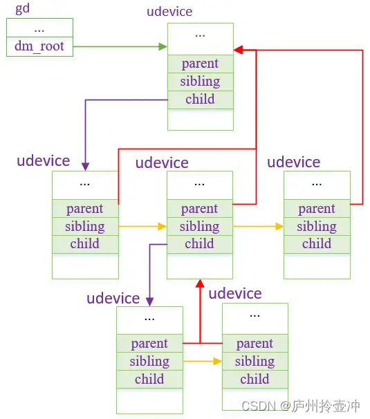
All udevice structures in the system can be connected together through parent, child_head and sibling_node, and finally hung on the dm_root node of gd, so that we can traverse all udevice devices through gd->dm_root. The figure below shows the connection relationship of udevice, where the parent of each node points to its parent node, sibling points to its sibling node, and child points to its child node.
Since each udevice belongs to a uclass, in addition to being connected to the gd->dm_root linked list, the udevice will also be linked to the uclass linked list. The connection relationship between them will be given when uclass is introduced below.
Udevice is dynamically created according to the scanned device in the driver model initialization process. The actual device in uboot can be defined in the following two ways:
(3-1) Devicetree method: This method maintains device information through devicetree. When uboot initializes the driver model, it obtains device information by parsing the device tree and completes its binding with the driver. (3-2) Hard-coded method
: This way a device can be defined by the following macro:
#define U_BOOT_DRVINFO(__name)						\
		ll_entry_declare(struct driver_info, __name, driver_info)
(4) uclass structure
uclass is used to represent a class of devices with the same function, so that a unified device access interface can be abstracted for it, which is convenient for other modules to call it. The following is the definition of uclass:
struct uclass {


	void *priv_;
	struct uclass_driver *uc_drv;
	struct list_head dev_head;
	struct list_head sibling_node;
}
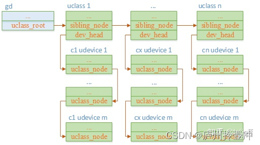
uclass hangs all devices belonging to this class on its dev_head linked list, and at the same time, all uclasses in the system will be hung on a global linked list gd->uclass_root. Its structure is as follows:
1.2.2 Initialization of the driving model
The driver model initialization mainly completes the binding relationship between udevice, driver and ucalss, etc., which mainly includes the following parts:
(1) Binding of udevice and driver
(2) Binding of udevice and uclass
(3) Binding of uclass and uclass_driver
The process is implemented by the dm_init_and_scan function, which scans the devices defined by U_BOOT_DRVINFO and devicetree respectively, allocates udevice structures to them, and completes operations such as the binding relationship with driver and uclass. It should be noted that this function will be called in both board_init_f and board_init_r, where board_init_f is mainly to resolve the device nodes that need to be used before relocation. This type of node will add u-boot and dm-pre-reloc attributes in devicetree. This piece of code flow is relatively clear, interested students can analyze it by themselves
1.3 Environment variables
Environment variables can provide uboot with the ability to dynamically configure parameters at runtime, such as changing the kernel startup parameters by modifying the environment variable bootargs on the command line. It is stored in the format of env=value, where each environment variable ends with '\0'. According to the configuration parameters of the system, uboot defines a default environment variable for the system in include/env_default.h:
#ifdef DEFAULT_ENV_INSTANCE_EMBEDDED
env_t embedded_environment __UBOOT_ENV_SECTION__(environment) = {


#ifdef CONFIG_SYS_REDUNDAND_ENVIRONMENT
	1,
#endif
	{


#elif defined(DEFAULT_ENV_INSTANCE_STATIC)
static char default_environment[] = {


#elif defined(DEFAULT_ENV_IS_RW)
uchar default_environment[] = {


#else
const uchar default_environment[] = {


#endif
#ifndef CONFIG_USE_DEFAULT_ENV_FILE
#ifdef	CONFIG_ENV_CALLBACK_LIST_DEFAULT
	ENV_CALLBACK_VAR "=" CONFIG_ENV_CALLBACK_LIST_DEFAULT "\0"
#endif
#ifdef	CONFIG_ENV_FLAGS_LIST_DEFAULT
	ENV_FLAGS_VAR "=" CONFIG_ENV_FLAGS_LIST_DEFAULT "\0"
#endif
#ifdef	CONFIG_USE_BOOTARGS
	"bootargs="	CONFIG_BOOTARGS			"\0"
#endif
#ifdef	CONFIG_BOOTCOMMAND
	"bootcmd="	CONFIG_BOOTCOMMAND		"\0"
#endif

…

#ifdef	CONFIG_EXTRA_ENV_SETTINGS
	CONFIG_EXTRA_ENV_SETTINGS
#endif
	"\0"
#else
#include "generated/defaultenv_autogenerated.h"
#endif
#ifdef DEFAULT_ENV_INSTANCE_EMBEDDED
	}
#endif
};
In this environment variable, the board can set its own default environment variable by redefining the value of CONFIG_EXTRA_ENV_SETTINGS. For example, for the qemu platform, its definition is located in include/configs/qemu-arm.h:
#define CONFIG_EXTRA_ENV_SETTINGS \
	"fdt_high=0xffffffff\0" \
	"initrd_high=0xffffffff\0" \
	"fdt_addr=0x40000000\0" \
	"scriptaddr=0x40200000\0" \
	"pxefile_addr_r=0x40300000\0" \
	"kernel_addr_r=0x40400000\0" \
	"ramdisk_addr_r=0x44000000\0" \
		BOOTENV
After the environment variable is modified, it can be saved to a fixed storage medium (such as flash, mmc, etc.), so that the latest value can be loaded after the next startup. Uboot defines the storage location of environment variables through the U_BOOT_ENV_LOCATION macro. For example, for mmc, it is defined as follows (env/mmc.c):
U_BOOT_ENV_LOCATION(mmc) = {


	.location	= ENVL_MMC,
	ENV_NAME("MMC")
	.load		= env_mmc_load,
#ifndef CONFIG_SPL_BUILD
	.save		= env_save_ptr(env_mmc_save),
	.erase		= ENV_ERASE_PTR(env_mmc_erase)
#endif
}
The specific storage location of environment variables in mmc can be set through configuration options or devicetree, such as for mmc:
(1) The devicetree method can set the following attributes u-boot, mmc-env-partition in the /config node
: specify the partition where the environment variable is stored, and the environment variable will be stored at the end of the partition
u-boot, mmc-env -offset: If the u-boot, mmc-env-partition attribute is not defined, this parameter is used to specify the offset of the environment variable on the mmc raw device. u-boot, mmc-
env-offset-redundant: Specifies the backup environment variable in Offset on mmc device
(2) Set CONFIG_ENV_OFFSET through configuration parameters
: same meaning as u-boot, mmc-env-offset
CONFIG_ENV_OFFSET_REDUND: same meaning as u-boot, mmc-env-offset-redundant
The following options are used to configure the length of the environment variable and the device it saves:
(1) CONFIG_ENV_SIZE: the maximum length of the environment variable
(2) CONFIG_ENV_IS_IN_XXX (such as CONFIG_ENV_IS_IN_MMC): the device type saved by the environment variable
(3) CONFIG_SYS_MMC_ENV_DEV: The device number saved by the environment variable
uboot will use crc32 to check the integrity of the data for the environment variables stored in the fixed media. If the data is damaged, it will use the default environment variables to reinitialize the values of the environment variables.
1.4 Command line
After uboot is initialized, you can press the key to enter the command line window. In this window, you can execute commands such as setting environment variables, downloading image files, and starting the kernel. The support of these commands greatly facilitates the debugging of uboot and kernel startup related processes. Uboot provides many built-in commands, such as md, mw, setenv, saveenv, tftpboot, bootm, etc. Uboot provides the following macros for command definition (include/command.h):
(1)U_BOOT_CMD
It is used to define a uboot command, which is defined as follows:
#define U_BOOT_CMD(_name, _maxargs, _rep, _cmd, _usage, _help)		\
		U_BOOT_CMD_COMPLETE(_name, _maxargs, _rep, _cmd, _usage, _help, NULL)
The meanings of the parameters are as follows:
_name: command name
_maxargs: maximum number of parameters
_rep: Whether the command is repeatable. The cmd_rep callback will output whether it is repeatable (after pressing Enter, the last executed command is executed again and it is repeatable)
_cmd: command processing function
_usage: usage information, short information displayed when executing help
_help: help information (detailed usage information displayed when executing help name)
(2)U_BOOT_CMD_WITH_SUBCMDS
It is used to define a uboot command with subcommands. The subcommands can avoid too much logic in the main command processing function. You can also define its own _rep parameter for each subcommand to independently process whether it can be executed repeatedly. Function.
It is defined as follows:
#define U_BOOT_CMD_WITH_SUBCMDS(_name, _usage, _help, ...)		\
	U_BOOT_SUBCMDS(_name, __VA_ARGS__)				\
	U_BOOT_CMDREP_COMPLETE(_name, CONFIG_SYS_MAXARGS, do_##_name,	\
			       _usage, _help, complete_##_name)
Its fixed parameters are as follows:
_name: main command name
_usage: usage information, short information displayed when executing help
_help: help information (detailed usage information displayed when executing help name)
The variable parameters section can be used to define the subcommand U_BOOT_SUBCMD_MKENT, which is defined as follows:
#define U_BOOT_SUBCMD_MKENT(_name, _maxargs, _rep, _do_cmd)		\
	U_BOOT_SUBCMD_MKENT_COMPLETE(_name, _maxargs, _rep, _do_cmd,	\
				     NULL)
The parameters of the subcommand are as follows:
_name: subcommand name
_axargs: The maximum number of parameters for subcommands
_rep: Whether the subcommand can be executed repeatedly
_do_cmd: command processing function for subcommands
(3) Take the wdt command as an example (cmd/wdt.c), which defines the main command wdt, and defines subcommands list, dev, start, etc.
static char wdt_help_text[] =
	"list - list watchdog devices\n"
	"wdt dev [<name>] - get/set current watchdog device\n"
	"wdt start <timeout ms> [flags] - start watchdog timer\n"
	"wdt stop - stop watchdog timer\n"
	"wdt reset - reset watchdog timer\n"
	"wdt expire [flags] - expire watchdog timer immediately\n";

U_BOOT_CMD_WITH_SUBCMDS(wdt, "Watchdog sub-system", wdt_help_text,
	U_BOOT_SUBCMD_MKENT(list, 1, 1, do_wdt_list),
	U_BOOT_SUBCMD_MKENT(dev, 2, 1, do_wdt_dev),
	U_BOOT_SUBCMD_MKENT(start, 3, 1, do_wdt_start),
	U_BOOT_SUBCMD_MKENT(stop, 1, 1, do_wdt_stop),
	U_BOOT_SUBCMD_MKENT(reset, 1, 1, do_wdt_reset),
	U_BOOT_SUBCMD_MKENT(expire, 2, 1, do_wdt_expire));
(4) If we need to customize a command, we can refer to the following process (take the test_cmd command as an example)
a Create a source file test_cmd.c in the cmd directory
b Add compilation rules to the Makefile in this directory:
obj-$(CONFIG_CMD_TEST_CMD) += test_cmd.o
c Add the corresponding configuration item CONFIG_CMD_TEST_CMD in the Kconfig file in this directory
d Add the command according to the signature command definition macro in test_cmd.c, and implement its command processing function
2 Board_init_f and board_init_r function flow
The function logic of board_init_f and board_init_r is relatively clear. Below we only give the flow chart of their calls, without going into details
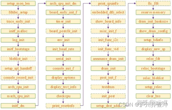
2.1 board_init_f process
board_init_f is the process before uboot relocation, which includes initialization of some basic modules and preparations related to relocation. The following is the possible execution flow of this function under the armv8 architecture. The dashed line box in the figure indicates that the process is configurable, and the solid line box indicates that it is mandatory.
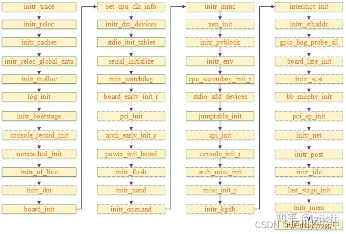
2.2 board_init_r process
board_init_r is the process that needs to be executed after uboot relocation. It includes the initialization of basic modules, hardware drivers, and board-level features, and finally starts the os through run_main_loop and enters the command line window.