Series Article Directory
This series started on December 25, 2022, and began to record the study notes during the research of the 3D reconstruction project, which is mainly divided into the following parts:
1. The conversion relationship between camera imaging and coordinate system
2. Camera calibration: Zhang Youzheng calibration method
3. Feature detection and matching
4. Exercise recovery structure method
Article directory
2. Coordinate system and conversion between them
2.1 Convert the world coordinate system to the camera coordinate system
2.2 Camera coordinate system to image coordinate system
2.3 Image coordinate system to pixel coordinate system
2.4 Expression of total transformation relationship
foreword
3D reconstruction is to use 2D information to restore 3D information, and the 2D information used by the passive vision method is an image sequence. First of all, if we want to go from 2D to 3D, we should first establish a mathematical model from 3D to 2D, and then study How to solve it inversely through the established mathematical model. Therefore, this article mainly introduces the principle of camera imaging and the relationship between the world coordinate system, camera coordinate system, image coordinate system and pixel coordinate system, and establishes a three-dimensional to two-dimensional mathematical model to lay the foundation for restoring three-dimensional information later.
1. Camera imaging principle
1.1 Pinhole imaging model
The most commonly used camera imaging model when studying camera imaging problems is pinhole imaging, also known as pinhole imaging, which simplifies the camera lens into a small hole, as shown in the following figure:
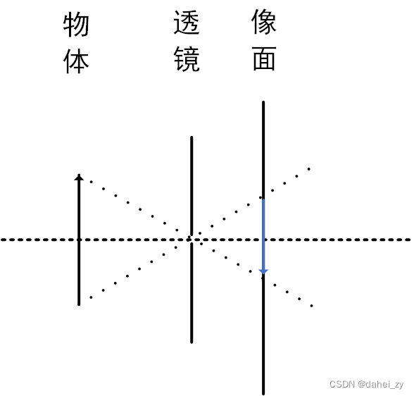
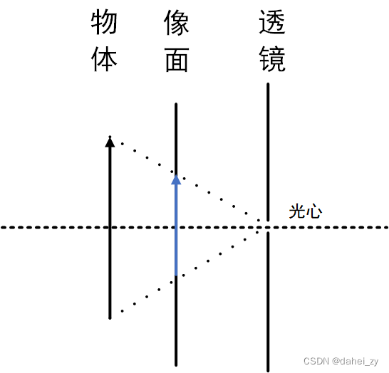
However, the image above is an inverted image, which is not conducive to subsequent research, so the imaging model moves the image plane to the front of the lens to facilitate subsequent research. The image at this time is a positive image, and the small hole is called the optical center:
For the pinhole imaging model, the effects of camera distortion and other effects are ignored, but a series of distortion and other parameters can be referenced later to supplement the pinhole imaging model.
1.2 3D representation
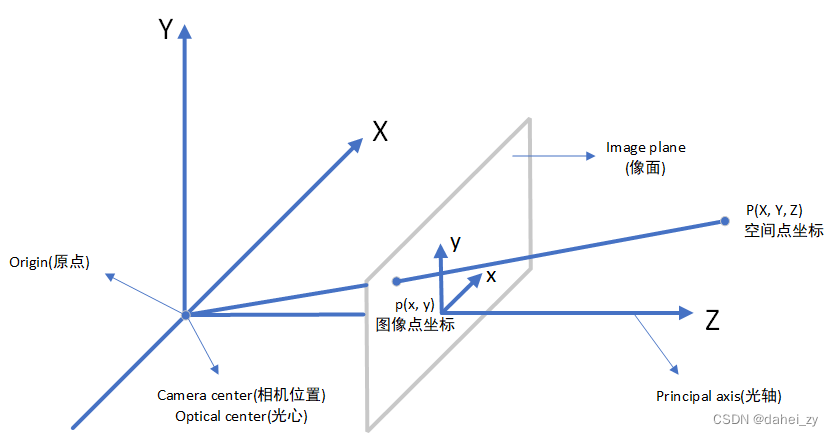
The three-dimensional expression of the pinhole imaging model is shown in the figure:
2. Coordinate system and conversion between them
There are mainly the following types of coordinate systems:
(1) World coordinate system : A reference coordinate system introduced to describe the position of the target in the real world.
(2) Camera coordinate system : a bridge connecting the world coordinate system and the image coordinate system. Generally, the optical axis of the camera is taken as the z-axis.
(3) Image coordinate system : introduced according to the projection relationship, it is convenient to further obtain pixel coordinates, the unit is mm, and the origin of the coordinates is the intersection position of the camera optical axis and the image physical coordinate system.
(4) Pixel coordinate system : the information actually read from the camera, the discretization of the physical coordinates of the image, in pixels, and the origin of the coordinates is in the upper left corner.
2.1 Convert the world coordinate system to the camera coordinate system

The conversion between the world coordinate system and the camera coordinate system is a rigid body transformation, and the object will not be deformed, but only translated and rotated between the coordinate systems. For the rigid transformation (rigid motion) between them, the original coordinate system is multiplied by a rotation matrix R and a translation vector T, so that the origin, X axis, Y axis and Z axis of the two coordinate axes coincide.
The corresponding rotation matrix can be obtained by rotating a coordinate system around its X-axis, Y-axis and Z-axis by different angles. Take rotation around the z-axis as an example:
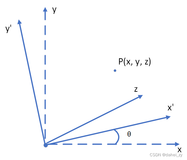
Therefore:
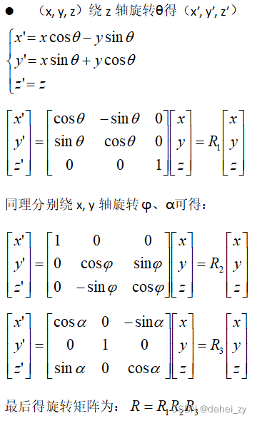
Therefore, the conversion of the coordinates of the 3D point P in the original world coordinates to the camera coordinate system is as follows:
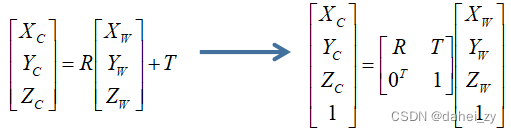
R is a 3×3 matrix; T is a 3×1 matrix.
2.2 Camera coordinate system to image coordinate system
The conversion from the world coordinate system to the camera coordinate system is a conversion between three-dimensional coordinates, and the conversion from the camera coordinate system to the image coordinate system is a conversion between three-dimensional and two-dimensional.

From the triangle similarity relationship in the figure, we can get:
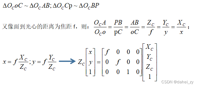
At this time, the coordinates of point P have been converted into coordinates of point p, but the unit of p coordinates at this time is not pixel pixel, but mm. Next, the image coordinate system will be converted to pixel coordinate system, and the converted coordinate unit will become pixel .
2.3 Image coordinate system to pixel coordinate system
The pixel coordinate system and the image coordinate system are ideally located on the same plane (image plane), but the units of the two are different from the origin position. The origin of the image coordinate system is the intersection o of the optical axis and the image plane, and the unit is mm; the origin of the pixel coordinate system is generally defined as the upper left corner of the image Ouv, and the unit is pixel. Generally, (u, v) is used to represent u column v row . dx and dy indicate how many mm each column and each row represent, that is, 1pixel=dx mm.
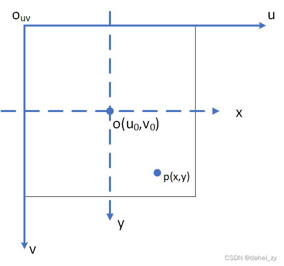

But sometimes, due to the problems in the manufacture of the camera, there will be a certain deviation between the image coordinate system and the pixel coordinate system. At this time, the coordinate system offset coefficient must be introduced to correct it. For the deviation of the two coordinate systems, it is required to find out the projected position of point p in the image coordinate system in the pixel coordinate system.
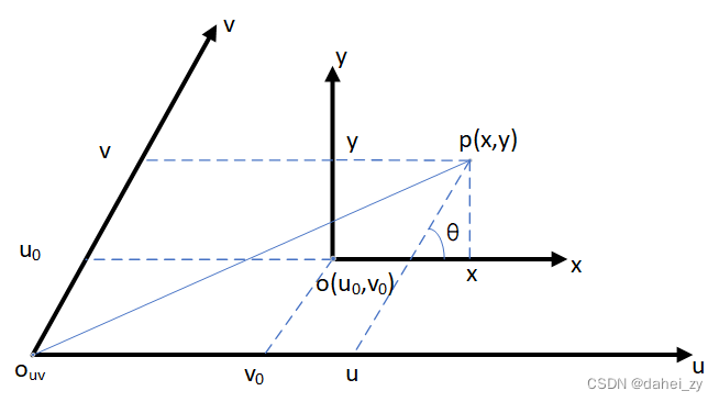
It can be understood as the angle between the horizontal and vertical axes of the pixel coordinate system in the image coordinate system (x, y). Ideally, the two coordinate systems are on the same plane,
which is 90°. When the camera is manufactured, the smaller the problem in this respect,
the closer to 90°.

This part is discovered when reading the data. Some data have a
parameter in the camera internal reference part (reflected in the general expression below), while others do not. In order to clarify the meaning of this parameter in the camera internal reference, we consulted the data and came to the above conclusion.
2.4 Expression of total transformation relationship

The parameters here
the difference in the upper and lower formulas is expressed as , for the convenience of subsequent expression and calculation
3. Camera Distortion ( distortion)
The above discussion does not include camera distortion, which is discussed separately here. The main cause of camera distortion is the lens, so camera distortion is also called lens distortion.
The position of camera distortion is from the ideal image coordinate system to the actual image coordinate system, that is, when the camera is transferred to the image coordinate system. Distortion is mainly divided into radial distortion and tangential distortion, and there are some other distortions such as: thin lens distortion, etc., but because the influence of other distortions is small, and the more complex distortion model will affect the analysis accuracy of distortion, so here Only radial and tangential distortions are considered.
3.1 Radial distortion ( Radial distortion)
Cause: the manufacturing process of the lens shape, the distortion of the center of the lens is small, and the distortion of the edge is large. The types include barrel distortion and pincushion distortion.

The first few terms of the Taylor series expansion at r=0 are often used to approximate the radial distortion:

Where: is the distortion parameter; (x, y) is the coordinate before distortion;
is the correction coordinate. r is the distance from the image pixel to the center of the image, ie
.
3.2 Tangential distortion ( tangential distortion)
Cause: The installation position error of the lens and CMOS or CCD. Therefore, a rectangle is likely to become a trapezoid when projected onto the imaging plane if tangential distortion is present. The coordinate relationship before and after correction is:

Where: is the distortion parameter; (x, y) is the coordinate before distortion;
is the correction coordinate. r is the distance from the image pixel to the center of the image, ie
.
Therefore, there are 5 distortion parameters needed to correct camera distortion: and
.
Summarize
Camera internal parameters and camera external parameters can be obtained through calibration methods. In addition, calibration methods can also obtain parameters such as the distortion of the corresponding camera. Zhang Zhengyou calibration method is widely used. The above content is the learning notes for the relevant knowledge of conversion between coordinate systems in 3D reconstruction. The next step of this series is divided into Zhang Zhengyou calibration method to obtain the internal and external parameter matrix of the camera.