Table of contents
1. Program flow and technical specification design
2. System hardware circuit design
3. Software writing and debugging
4. System debugging test and analysis
foreword
With the rapid development of my country's scientific and technological level and the continuous advancement of traditional flower planting facilities and industrialization, my country's scientific and technological development in the field of flower planting has entered a new stage. At this stage, the main goal of the development of my country's flower planting industry is not only to build a high-level modern flower planting industry, but also to improve the competitiveness of the industry in the international market. This has also become an important task for the development of the flower planting industry in my country at present and in the future.
In recent years, my country's greenhouse industry has developed rapidly, and the area of greenhouses ranks first in the world. According to statistics, the solar greenhouses and plastic greenhouses in my country have reached 3.3 million hectares (4.96 million mu) and 670 hectares (10.07 million mu) respectively. However, my country's greenhouse automatic control technology is far behind the growth of the number of greenhouses. Farmers are still using a lot of human labor, which is not only tiring, but also wastes a lot of resources because of the inability to accurately monitor the greenhouse environment. Crop yields have suffered, reducing incomes. Compared with modern agriculture in developed countries, there is still a considerable gap, especially in the automatic control of various factors in the greenhouse production environment.
The construction of advanced greenhouses is conducive to solving the problem of relying on the weather, preventing bad weather, eliminating seasonal factors to create a suitable growth environment for organisms, eliminating environmental factors that are unfavorable to crop growth to promote biological growth, and making it partially or completely overcome the external climate In order to shorten the growth cycle of crops, increase the yield of crops, and obtain certain economic benefits.
The purpose of this project is to study a greenhouse automatic detection and control system based on a single-chip microcomputer as the main control chip, which is used to monitor temperature, humidity, and light, process data and control water spraying and lighting equipment through the single-chip microcomputer, and automatically complete the control of the flower greenhouse. And has an alarm function. This system can control the greenhouse in an ideal temperature, humidity and light environment, which is conducive to the growth of flowers, and is fully automatic, saving manpower and material resources, and has very good practical and popularization value.
Software Tool Preparation
software:
Circuit design: protel99 se (up main version) or other versions, or other circuit design software;
MCU development: Keil5;
Debugging test: serial port debugging assistant, logic analyzer, etc.;
tool:
Circuit welding: electric soldering iron, SMT (conditional);
debugging:
Multimeter, oscilloscope (basic entry is enough, you can go to school or company for nothing) USB to serial port tool, emulator;
1. Program flow and technical specification design
Scheme process design

Technical specification design
1. This design uses DHT11 temperature and humidity sensor, photoresistor to detect temperature, humidity and illuminance. Use 320X240TFT color LCD to display greenhouse parameters.
2. The single-chip microcomputer collects temperature, humidity and illuminance. After processing the data, it controls the lighting and water spray equipment to keep the temperature, humidity and light at the set state .
3. The control equipment includes lights (LED light simulation), water spray equipment (relay output).
4. If it exceeds the setting range, the system buzzer will give an alarm.
5. 4 buttons can set the alarm parameters.
2. System hardware circuit design
This design uses STM32F103 microcontroller, DHT11 temperature and humidity sensor, TFT LCD liquid crystal display, photoresistor, buzzer and LED alarm circuits. The microcontroller communicates with the DHT11 temperature and humidity sensor to collect temperature and humidity values. The photoresistor outputs an analog signal, which is processed by AD conversion to obtain light. When the temperature and humidity exceed the range, an audible and visual alarm will be given.

2 .1 Microprocessor control circuit
The system uses STM32F103C8T6 microcontroller. LQFP48 package, STM32F103 is an ARM series microcontroller, the circuit diagram is shown in the figure:

The power supply voltage of VCC3.3 in the figure is 3.3V. R12, C19 reset circuit, C20, C101, C102 filter function, J6 is the emulation programming port.
SCM IO port connection introduction:
PB0-PB2 (pin 18-20): LCD data port.
PB3-PB7 (pin 39-43): LCD data port.
PB8-PB9 (pin 45-46): LCD data port.
PB10-PB11 (pin 21-22): LCD data port.
PB12-PB15 (pin 25-28): LCD data port.
PC13-PC14: LCD control.
PA8-PA9: LCD control.
PA7: LCD backlight.
PA0-PA2: Buttons.
PA3: photoresistor input.
PA4: Buzzer control.
PA5: LED light control.
PA6: DHT11 temperature and humidity control.
2.2 Temperature and humidity sensor circuit
DHT11 is an integrated temperature and humidity sensor, built-in MCU, single-line digital communication between the temperature and humidity sensor and the single-chip microcomputer, the circuit is as shown in the figure:

Pin 1 is the power supply VCC, pin 4 is grounded, and pin 2 is the sensor output pin. C18 filter, R21 pull-up resistor.
2.3 TFT LCD display circuit
The design adopts 2.8-inch TFT LCD, 16-bit parallel bus, the control chip is ILI9341, the circuit is as shown in the figure:
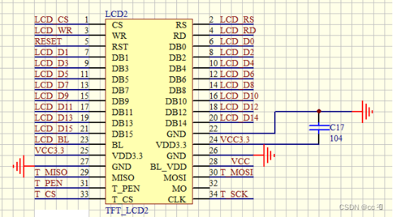
C17 is a filter capacitor. IO port connection introduction:
LCD_CS, LCD_RS, LCD_WR, LCD_RD (1-4 pins): LCD read and write control pins.
RESET (pin 5): Reset.
LCD_D0-LCD_D15 (pin 6-21): LCD data interface.
LCD_BL (23 feet): backlight control.
VCC3.3, GND: power supply and ground.
BL_VDD (28 feet): backlight power supply.
The other pins are touch screen control pins, which are not used in this design.
2.4 Button circuit
If the button is not pressed, the corresponding IO port is high level, and the button is pressed, and the corresponding IO port is grounded, which is low level. The single-chip microcomputer detects the level of the IO port of each button, and judges the status of the button. The circuit is shown in the figure:

2.5 LED circuit
The LED is controlled by the IO port of the microcontroller, and R22 is a current limiting resistor. The circuit is shown in the figure.

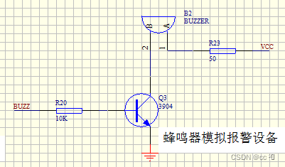
2.6 Buzzer drive circuit
The buzzer simulates an alarm device. Due to the limited driving capability of the IO port, a triode amplifier circuit is used to expand the driving current. The circuit is shown in the figure.
2.7 Photoresistor circuit
G1 is a photoresistor, R14 is a fixed resistor, and OK is an output signal. The larger the resistance of the photoresistor, the larger the output signal. After AD conversion, the illuminance can be judged. The photoresistor interface circuit is shown in the figure:

2.8 Power circuit
The power supply is the energy supply center of the entire system, and a stable voltage is a necessary condition for the system to work. Because both the single-chip microcomputer and the temperature and humidity sensor need a power supply with less ripple and less interference, the system uses a linear voltage regulator circuit. The external 9V power adapter outputs 5V through 7805 regulated voltage, C4 input filter capacitor, C5 output filter capacitor. The circuit is shown in the figure.

The 3.3V power supply of the single-chip microcomputer adopts the ASM1117 linear voltage regulator circuit, and the circuit is as shown in the figure.

3. Software writing and debugging
3.1 Main program design
This system uses STM32F103C8T6 single-chip microcomputer main control chip, the sensor uses DHT11 temperature and humidity sensor, photosensitive resistance sensor, the control part has relay control, buzzer alarm control, LED light control. First, you need to initialize the microcontroller system clock and peripherals. When working normally, the DHT11 module detects the temperature and humidity, and the single-chip single-wire communication reads the temperature and humidity values. Photoresistors detect light conditions. The single-chip microcomputer judges the temperature value, humidity value, and light conditions, and turns on the lighting equipment and irrigation equipment if the conditions are met. If the temperature value exceeds the preset range, the control buzzer will alarm.
MCU programming generally uses assembly language and C language. Assembly language is close to machine language, it is difficult to learn, and it is difficult to realize complex calculation and logic control. C language is close to human language, easy to understand, and relatively easy to realize calculation and logic control. This design uses C voice design program.
This system needs to realize the detection of temperature, humidity and light, and control the switch of lighting equipment and irrigation equipment through calculation and analysis, so as to realize the effect of constant temperature and constant humidity in the greenhouse. When the temperature exceeds a certain range, the buzzer will alarm to remind the management personnel to deal with it.
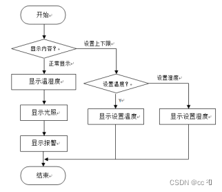
The picture is the flow chart of the main program. The single-chip microcomputer reads the temperature and humidity of DHT11, judges the temperature and humidity, turns on and off the lighting equipment and irrigation equipment. If the temperature exceeds the range, the control buzzer will sound.
After the system is powered on, first initialize the microcontroller, and then enter the working state.

3 .2 Program design of DHT11 temperature and humidity sensor
DHT11 temperature and humidity sensor is a digital sensor, which has a resistive humidity sensing element and an NTC temperature measuring element inside, and is connected with a high-performance 8-bit microcontroller. The connection with the microcontroller adopts a single bus. The communication time is about 4ms, and the data is divided into decimal part and integer part. The specific format is explained below. The current decimal part is used for future expansion, and it is now read as zero. The operation process is as follows: a complete data transmission is 40bit, high-order first out. Data Format:
8bit humidity integer data+8bit humidity decimal data
+8bi temperature integer data +8bit temperature decimal data
+8bit checksum
When the data transmission is correct, the checksum data is equal to the last 8 bits of the result obtained by "8bit humidity integer data + 8bit humidity decimal data + 8bi temperature integer data + 8bit temperature decimal data".
After the user MCU sends a start signal, DHT11 switches from low power consumption mode to high speed mode, and waits for the end of the host start signal, DHT11 sends a response signal, sends 40bit data, and triggers a signal acquisition, and the user can choose to read part of the data. In slave mode, DHT11 receives a start signal to trigger a temperature and humidity collection. If it does not receive a start signal from the host, DHT11 will not actively collect temperature and humidity. After collecting data, it will switch to low-speed mode.
1. The communication process is shown in the figure
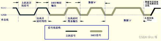
2. The idle state of the bus is high level, the host pulls the bus down and waits for DHT11 to respond, the host must pull the bus down for more than 18 milliseconds to ensure that DHT11 can detect the start signal. After receiving the host's start signal, DHT11 waits for the host's start signal to end, and then sends an 80us low-level response signal. After the host sends the start signal, waits for a delay of 20-40us, reads the DHT11's response signal, and the host sends a start signal After that, it can switch to input mode, or output high level, and the bus is pulled high by the pull-up resistor. The picture is the communication between the host and DHT11.

The picture is the program flow chart of DHT11 temperature and humidity sensor.

code:
#include "stm32f10x.h"
#include "dht11.h"
#define TRH PAout(6) // PA6
#define TRH_in PAin(6) // PA6
u8 str[]={0,0,0,0,0,0,0,0};
u16 TH,TL,RH,RL,CK;
u16 THc,TLc,RHc,RLc,CKc;
u16 xh,sum;
//IO initialization PA6
void DHT11_io_Output(void)
{
GPIO_InitTypeDef GPIO_InitStructure;
GPIO_InitStructure.GPIO_Pin = GPIO_Pin_6; //LED0-->PA.6 port configuration
GPIO_InitStructure.GPIO_Mode = GPIO_Mode_Out_PP; //Push-pull output
GPIO_InitStructure.GPIO_Speed = GPIO_Speed_50MHz; //The speed is 50MHz
GPIO_Init(GPIOA, &GPIO_InitStructure); //Initialize according to the set parameters
}
void DHT11_io_Input(void)
{
GPIO_InitTypeDef GPIO_InitStructure;
GPIO_InitStructure.GPIO_Pin = GPIO_Pin_6;
GPIO_InitStructure.GPIO_Mode = GPIO_Mode_IPU;
GPIO_InitStructure.GPIO_Speed = GPIO_Speed_50MHz;
GPIO_Init(GPIOA, &GPIO_InitStructure);
}
void delay(u8 b) //error 0us
{
unsigned char a;
for(;b>0;b--)
{
for(a=2;a>0;a--);
}
}
void delay1(u8 c) //error 0us
{
unsigned char a,b;
for(;c>0;c--)
{
for(b=142;b>0;b--)
{
for(a=2;a>0;a--);
{
}
}
}
}
void start()
{
TRH = 1;
delay(2);
TRH = 0; //The host pulls down for 18ms
delay1(20);
TRH = 1; //The DATA bus is pulled up by the pull-up resistor and the host delay is 20
delay(3);
}
u8 receive()
{
u8 i,temp;
xh=0;
while(TRH);
for(i=0;i<8;i++)
{
while(!TRH);
delay(3);
if(TRH)
{
temp=1;
while(TRH);
}
else
{
temp=0;
xh<<=1;
xh|=temp;
}
}
return (xh);
}
void read_dht11(void)
{
while(1)
{
start();
TRH=1; // read data and write command
if(!TRH)
{
while(!TRH);//judging whether the 80us low-level response signal sent by DHT11 is over
while(TRH);
delay(8);
RHc = receive(); //Data receiving status
RLc = receive();
THc = receive();
TLc = receive();
CKc = receive();
}
TRH=1;
sum=(RHc+RLc+THc+TLc);//data verification
if(sum==CKc)
{
RH = RHc;
RL = RLc;
TH= THc;
TL = TLc;
CK = CKc;
str[0] =RH/10; //Humidity integer part
str[1] =RH%10;
str[2] = RL/10 ;
str[3] = TH/10; //Integer part of temperature
str[4] = TH%10;
str[5] = TL/10;
}
}
}
3.3 TFT LCD display program design
The liquid crystal display used in this design is 320x240TFTLD. TFTLCD screens controlled by single-chip microcomputers generally have MCU screens and RGB screens. The MCU screen has a built-in LCD driver and display RAM, and the interface is relatively simple. The screen driver IC in this design is ILI9341.
TFTLCD display uses red, green and blue three primary colors to synthesize various colors, referred to as RGB. ILI9341 can display 8x8x8 total 24-bit true color. Since the IO port of the single-chip microcomputer is 16 bits, in order to speed up the refresh rate, the design uses 16-bit true color.
The ILI9341 driver needs to be initialized before displaying. The first is the initialization of the IO port of the microcontroller, and then the LCD initialization.
Initialization code:
//write register function
void LCD_WR_REG(u16 data)
{
LCD_RS_CLR;//write address
LCD_CS_CLR;
DATAOUT(data);
LCD_WR_CLR;
LCD_WR_SET;
LCD_CS_SET;
}
//write data function
void LCD_WR_DATAX(u16 data)
{
LCD_RS_SET;
LCD_CS_CLR;
DATAOUT(data);
LCD_WR_CLR;
LCD_WR_SET;
LCD_CS_SET;
}
//Initialize lcd
void LCD_Init(void)
{
GPIO_InitTypeDef GPIO_InitStructure;
RCC_APB2PeriphClockCmd(RCC_APB2Periph_GPIOC|RCC_APB2Periph_GPIOB|RCC_APB2Periph_GPIOA|RCC_APB2Periph_AFIO, ENABLE); //Enable PORTA, B, C clock and AFIO clock
GPIO_PinRemapConfig(GPIO_Remap_SWJ_JTAGDisable , ENABLE);//Enable SWD, disable JTAG
GPIO_InitStructure.GPIO_Pin = GPIO_Pin_9|GPIO_Pin_8|GPIO_Pin_7; ///PORTA7~9 multiplexed push-pull output
GPIO_InitStructure.GPIO_Mode = GPIO_Mode_Out_PP;
GPIO_InitStructure.GPIO_Speed = GPIO_Speed_50MHz;
GPIO_Init(GPIOA, &GPIO_InitStructure); //GPIOA
GPIO_InitStructure.GPIO_Pin = GPIO_Pin_13|GPIO_Pin_14; ///PORTC13, 14 multiplexed push-pull output
GPIO_InitStructure.GPIO_Mode = GPIO_Mode_Out_PP;
GPIO_InitStructure.GPIO_Speed = GPIO_Speed_50MHz;
GPIO_Init(GPIOC, &GPIO_InitStructure); //GPIOC
GPIO_SetBits(GPIOC,GPIO_Pin_13|GPIO_Pin_14);
GPIO_SetBits(GPIOA,GPIO_Pin_7|GPIO_Pin_8|GPIO_Pin_9);
GPIO_InitStructure.GPIO_Pin = GPIO_Pin_All; // PORTB push-pull output
GPIO_Init(GPIOB, &GPIO_InitStructure); //GPIOB
GPIO_SetBits(GPIOB,GPIO_Pin_All);
delay_ms(50); // delay 50 ms
LCD_WriteReg(0x0000,0x0001);
delay_ms(50); // delay 50 ms
lcddev.id = LCD_ReadReg(0x0000);
//9341 initialization
LCD_WR_REG(0xCF);
LCD_WR_DATAX(0x00);
LCD_WR_DATAX(0xC1);
LCD_WR_DATAX(0X30);
LCD_WR_REG(0xED);
LCD_WR_DATAX(0x64);
LCD_WR_DATAX(0x03);
LCD_WR_DATAX(0X12);
LCD_WR_DATAX(0X81);
LCD_WR_REG(0xE8);
LCD_WR_DATAX(0x85);
LCD_WR_DATAX(0x10);
LCD_WR_DATAX(0x7A);
LCD_WR_REG(0xCB);
LCD_WR_DATAX(0x39);
LCD_WR_DATAX(0x2C);
LCD_WR_DATAX(0x00);
LCD_WR_DATAX(0x34);
LCD_WR_DATAX(0x02);
LCD_WR_REG(0xF7);
LCD_WR_DATAX(0x20);
LCD_WR_REG(0xEA);
LCD_WR_DATAX(0x00);
LCD_WR_DATAX(0x00);
LCD_WR_REG(0xC0); //Power control
LCD_WR_DATAX(0x1B); //VRH[5:0]
LCD_WR_REG(0xC1); //Power control
LCD_WR_DATAX(0x01); //SAP[2:0];BT[3:0]
LCD_WR_REG(0xC5); //VCM control
LCD_WR_DATAX(0x30); //3F
LCD_WR_DATAX(0x30); //3C
LCD_WR_REG(0xC7); //VCM control2
LCD_WR_DATAX(0XB7);
LCD_WR_REG(0x36); // Memory Access Control
LCD_WR_DATAX(0x48);
LCD_WR_REG(0x3A);
LCD_WR_DATAX(0x55);
LCD_WR_REG(0xB1);
LCD_WR_DATAX(0x00);
LCD_WR_DATAX(0x1A);
LCD_WR_REG(0xB6); // Display Function Control
LCD_WR_DATAX(0x0A);
LCD_WR_DATAX(0xA2);
LCD_WR_REG(0xF2); // 3Gamma Function Disable
LCD_WR_DATAX(0x00);
LCD_WR_REG(0x26); //Gamma curve selected
LCD_WR_DATAX(0x01);
LCD_WR_REG(0xE0); //Set Gamma
LCD_WR_DATAX(0x0F);
LCD_WR_DATAX(0x2A);
LCD_WR_DATAX(0x28);
LCD_WR_DATAX(0x08);
LCD_WR_DATAX(0x0E);
LCD_WR_DATAX(0x08);
LCD_WR_DATAX(0x54);
LCD_WR_DATAX(0XA9);
LCD_WR_DATAX(0x43);
LCD_WR_DATAX(0x0A);
LCD_WR_DATAX(0x0F);
LCD_WR_DATAX(0x00);
LCD_WR_DATAX(0x00);
LCD_WR_DATAX(0x00);
LCD_WR_DATAX(0x00);
LCD_WR_REG(0XE1); //Set Gamma
LCD_WR_DATAX(0x00);
LCD_WR_DATAX(0x15);
LCD_WR_DATAX(0x17);
LCD_WR_DATAX(0x07);
LCD_WR_DATAX(0x11);
LCD_WR_DATAX(0x06);
LCD_WR_DATAX(0x2B);
LCD_WR_DATAX(0x56);
LCD_WR_DATAX(0x3C);
LCD_WR_DATAX(0x05);
LCD_WR_DATAX(0x10);
LCD_WR_DATAX(0x0F);
LCD_WR_DATAX(0x3F);
LCD_WR_DATAX(0x3F);
LCD_WR_DATAX(0x0F);
LCD_WR_REG(0x2B);
LCD_WR_DATAX(0x00);
LCD_WR_DATAX(0x00);
LCD_WR_DATAX(0x01);
LCD_WR_DATAX(0x3f);
LCD_WR_REG(0x2A);
LCD_WR_DATAX(0x00);
LCD_WR_DATAX(0x00);
LCD_WR_DATAX(0x00);
LCD_WR_DATAX(0xef);
LCD_WR_REG(0x11); //Exit Sleep
delay_ms(120);
LCD_WR_REG(0x29); //display on
LCD_Display_Dir(0); //The default is horizontal screen
LCD_LED = 1; // turn on the backlight
LCD_Clear(WHITE);
}
After the initialization is complete, the content can be displayed normally. Normal working status, display temperature, humidity, light. If there is an alarm, the alarm information will be displayed. Setting status, displaying the setting value. The figure is a flow chart showing the function.
code:
//Display a character at the specified position
//x,y: starting coordinates
//num: characters to be displayed: " "--->"~"
//size: font size 12/16/24
//mode: superposition mode (1) or non-superposition mode (0)
void LCD_ShowChar(u16 x,u16 y,u8 num,u8 size,u8 mode)
{
u8 temp,t1,t;
u16 y0=y;
u8 csize=(size/8+((size%8)?1:0))*(size/2); //Get the number of bytes occupied by one character of the font corresponding to the lattice set
num=num-' ';//Get the value after the offset (ASCII font is modulo from the space, so -' 'is the font of the corresponding character)
for(t=0;t<csize;t++)
{
if(size==12)
{
temp=asc2_1206[num][t]; //call 1206 font
}
else if(size==16)
{
temp=asc2_1608[num][t]; //call 1608 font
}
else if(size==24)
{
temp=asc2_2412[num][t]; //call 2412 font
}
else
{
return;
}
for(t1=0;t1<8;t1++)
{
if(temp&0x80)
{
LCD_Fast_DrawPoint(x,y,POINT_COLOR);
}
else if(mode==0)
{
LCD_Fast_DrawPoint(x,y,BACK_COLOR);
}
temp<<=1;
y++;
if(y>=lcddev.height)
{
return; // super area
}
if((y-y0)==size)
{
y=y0;
x++;
if(x>=lcddev.width)
{
return; // super area
}
break;
}
}
}
}
//m^n function
//Return value: m^n power.
u32 LCD_Pow(u8 m,u8 n)
{
u32 result=1;
while(n--)
{
result *= m;
}
return result;
}
//Display the number, if the high bit is 0, it will not be displayed
//x,y: starting point coordinates
//len: the number of digits
//size: font size
//color: color
//num: value (0~4294967295);
void LCD_ShowNum(u16 x,u16 y,u32 num,u8 len,u8 size)
{
u8 t,temp;
u8 enshow=0;
for(t=0;t<len;t++)
{
temp=(num/LCD_Pow(10,len-t-1))%10;
if(enshow==0&&t<(len-1))
{
if(temp==0)
{
LCD_ShowChar(x+(size/2)*t,y,' ',size,0);
continue;
}else enshow=1;
}
LCD_ShowChar(x+(size/2)*t,y,temp+'0',size,0);
}
}
//display string
//x,y: starting point coordinates
//width, height: area size
//size: font size
//*p: string starting address
void LCD_ShowString(u16 x,u16 y,u16 width,u16 height,u8 size,u8 *p)
{
u8 x0 = x;
width += x;
height += y;
while((*p<='~')&&(*p>=' '))//Judge whether it is an illegal character!
{
if(x >= width)
{
x = x0;
y+=size;
}
if(y >= height)
break;//exit
LCD_ShowChar(x,y,*p,size,0);
x+=size/2;
p++;
}
}
//boot menu
void Dsp_On(void)
{
POINT_COLOR = RED;
LCD_ShowString(10,10,200,24,24,"temperature:");
POINT_COLOR = WHITE;
LCD_ShowxNum(10,40,Temproom,3,24,0);
LCD_ShowChar(50,40,'C',24,0);
POINT_COLOR = RED;
LCD_ShowString(10,80,200,24,24,"humidity:");
POINT_COLOR = WHITE;
LCD_ShowxNum(10,110,Ground,3,24,0);
LCD_ShowChar(50,110,'%',24,0);
POINT_COLOR = RED;
LCD_ShowString(10,150,200,24,24,"light:");
POINT_COLOR = WHITE;
LCD_ShowxNum(10,180,Light,3,24,0);
LCD_ShowChar(50,180,'%',24,0);
}
//setting menu
void Dsp_Setup(void)
{
POINT_COLOR = RED;
LCD_ShowString(10,10,200,24,24,"Setup: ");
POINT_COLOR = WHITE;
LCD_ShowxNum(10,40,TempMax,3,24,0);
LCD_ShowChar(46,40,'C',24,0);
POINT_COLOR = BLUE;
LCD_ShowString(10,80,200,24,24," ");
POINT_COLOR = BLUE;
LCD_ShowxNum(10,110,Ground,3,24,0);
LCD_ShowChar(46,110,'%',24,0);
POINT_COLOR = BLUE;
LCD_ShowString(10,150,200,24,24,"light:");
POINT_COLOR = BLUE;
LCD_ShowxNum(10,180,Light,3,24,0);
LCD_ShowChar(46,180,'%',24,0);
}
//display tasks
void DisplayTask(void)
{
if(WorkState == WORK_STATE_NORMAL)
{
Dsp_On();
}
else
{
Dsp_Setup();
}
}
3.4 Buzzer Driver Design
When the temperature exceeds the range, the buzzer will sound to remind the management personnel. The buzzer is a 4KHz passive buzzer that requires a 4KHz square wave drive. The design uses a 125US timer to regularly flip the IO port level and output a 4KHz square wave. The input and output ports of the buzzer need to be initialized, and the push-pull output function should be configured.
code:
void Buzz_io_init(void)
{
GPIO_InitTypeDef GPIO_InitStructure;
GPIO_InitStructure.GPIO_Pin = GPIO_Pin_4; //LED0-->PA.4 port configuration
GPIO_InitStructure.GPIO_Mode = GPIO_Mode_Out_PP; //Push-pull output
GPIO_InitStructure.GPIO_Speed = GPIO_Speed_50MHz; //IO port speed is 50MHz
GPIO_Init(GPIOA, &GPIO_InitStructure); //Initialize GPIOA.8 according to the set parameters
GPIO_ResetBits(GPIOA,GPIO_Pin_4); //PA.5 output high
}
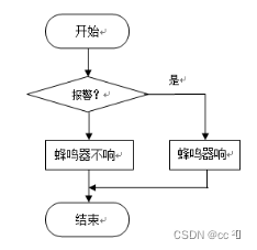
The function of the buzzer is relatively simple, that is, in the alarm state, the buzzer sounds, and the buzzer does not sound in other states. The figure is a flowchart of the buzzer alarm function.
code:
//Set the buzzer sound time
void User_SetBeepTime(void)
{
TimerBeepOn = TIMER_BEEP_ON;
}
//buzzer ringing time calculation
void User_BeepTick(void)
{
if(TimerBeepOn)
{
TimerBeepOn--;
}
}
//buzzer sound task
void User_BeepTask(void)
{
if(TimerBeepOn)
{
if(BeepState)
{
BeepState = 0;
GPIO_ResetBits(GPIOA,GPIO_Pin_4);
}
else
{
BeepState = 1;
GPIO_SetBits(GPIOA,GPIO_Pin_4);
}
}
else
{
BeepState = 0;
GPIO_ResetBits(GPIOA,GPIO_Pin_4);
}
}
//initialization
void User_BeepInit(void)
{
TimerBeepOn = 0;
Buzz_io_init();
}
4.5 Program design of photoresistor
Photoresistors are sensitive to visible light. When there is no light, the resistance value is very large, usually hundreds of kiloohms to several megohms. When there is light, the resistance value decreases. The stronger the light, the smaller the resistance value, the minimum is only a few thousand Oh, through the resistance of the photoresistor, the light intensity can be obtained.
There is a 12-bit AD converter inside the STM32F103 microcontroller, so the internal converter is used. The AD conversion function needs to initialize and configure the AD converter. Otherwise its functions cannot be used. Since the photoresistor input signal is connected to PA3, configure channel 3 as AD input.
code:
//Initialize ADC
//We will enable channel 3
void Adc_Init(void)
{
ADC_InitTypeDef ADC_InitStructure;
GPIO_InitTypeDef GPIO_InitStructure;
RCC_APB2PeriphClockCmd(RCC_APB2Periph_GPIOA |RCC_APB2Periph_ADC1 , ENABLE ); //Enable ADC1 channel clock
RCC_ADCCLKConfig(RCC_PCLK2_Div6); //Set ADC frequency division factor 6 72M/6=12, ADC maximum time cannot exceed 14M
//PA3 is used as an analog channel input pin
GPIO_InitStructure.GPIO_Pin = GPIO_Pin_3;
GPIO_InitStructure.GPIO_Mode = GPIO_Mode_AIN; //analog input pin
GPIO_Init(GPIOA, &GPIO_InitStructure);
ADC_DeInit(ADC1); //Reset ADC1, reset all registers of peripheral ADC1 to default values
ADC_InitStructure.ADC_Mode = ADC_Mode_Independent; //ADC working mode: ADC1 and ADC2 work in independent mode
ADC_InitStructure.ADC_ScanConvMode = DISABLE; //ADC works in single channel mode
ADC_InitStructure.ADC_ContinuousConvMode = DISABLE; //ADC works in single conversion mode
ADC_InitStructure.ADC_ExternalTrigConv = ADC_ExternalTrigConv_None; // conversion is initiated by software rather than external trigger
ADC_InitStructure.ADC_DataAlign = ADC_DataAlign_Right; //ADC data right alignment
ADC_InitStructure.ADC_NbrOfChannel = 1; //The number of ADC channels for regular conversion in sequence
ADC_Init(ADC1, &ADC_InitStructure); //Initialize the peripheral ADCx registers according to the parameters specified in ADC_InitStruct
ADC_Cmd(ADC1, ENABLE); //Enable the specified ADC1
//ADC_ResetCalibration(ADC1); //Enable reset calibration
//while(ADC_GetResetCalibrationStatus(ADC1)); //Wait for the end of reset calibration
//ADC_StartCalibration(ADC1); //Open AD calibration
//while(ADC_GetCalibrationStatus(ADC1)); //Wait for the calibration to end
// ADC_SoftwareStartConvCmd(ADC1, ENABLE); //Enable the software conversion start function of the specified ADC1
}
After the AD initialization is completed, read the AD value and calculate the signal strength to calculate the illumination. The figure is a photoresistor AD conversion and calculation flow chart.

code:
//Get ADC value
//ch: channel value 3
u16 Get_Adc(u8 ch)
{
//Set the rule group channel of the specified ADC, a sequence, sampling time
ADC_RegularChannelConfig(ADC1, ch, 1, ADC_SampleTime_239Cycles5 ); //ADC1, ADC channel, sampling time is 239.5 cycles
ADC_SoftwareStartConvCmd(ADC1, ENABLE); //Enable the software conversion start function of the specified ADC1
while(!ADC_GetFlagStatus(ADC1, ADC_FLAG_EOC ));//Wait for the conversion to end
return ADC_GetConversionValue(ADC1); //Return the conversion result of the latest ADC1 rule group
}
u16 Get_Adc_Average(u8 ch,u8 times)
{
u32 temp_val=0;
u8 t;
for(t=0;t<times;t++)
{
temp_val+=Get_Adc(ch);
delay_ms(5);
}
return temp_val/times;
}
// get light intensity
u16 lightAD;
void Read_LightAD(void)
{
lightAD = Get_Adc(ADC_Channel_3);
if(lightAD > LIGHT_AD_0)
{
Light = 0;
}
else if(lightAD > LIGHT_AD_25)
{
Light = 25;
}
else if(lightAD > LIGHT_AD_50)
{
Light = 50;
}
else if(lightAD > LIGHT_AD_75)
{
Light = 75;
}
else
{
Light = 100;
}
}
4. System debugging test and analysis
4.1 Circuit simulation
Proteus software is an EDA tool software published by Lab Center Electronics, UK . It not only has the simulation function of other EDA tool software, but also can simulate single-chip microcomputer and peripheral devices. It is a better tool for simulating microcontrollers and peripheral devices. So this design uses Proteus simulation. Since the used version does not have the DHT11 temperature and humidity sensor and the single-chip microcomputer does not have the AD conversion function, the humidity and light are not simulated. TFT LCD is replaced by 12864 dot matrix LCD.
1. Adjust the 18B20 temperature sensor to 32 degrees, the LCD displays 32 degrees, and the system functions normally.

2. Adjust the 18B20 temperature sensor to 39 degrees, the LCD displays 39 degrees, and the system functions normally.

4.2 Hardware circuit soldering
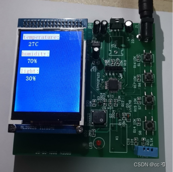
Solder the single chip microcomputer, DHT11 temperature and humidity sensor, photoresistor, LED light, liquid crystal display and capacitor, buzzer, button and other components on the circuit board with an electric soldering iron, as shown in the figure.

4.3 System debugging
Connect the computer and the single-chip microcomputer through the emulator, download the C program to the single-chip microcomputer, after power on, the single-chip microcomputer works normally, as shown in the figure: