LED positive and negative poles: big red flag - negative pole, small red flag - positive pole
How to see the resistor/capacitor value in the schematic diagram:
eg:
102 = 10 2 = 10 * 10 ^ 2 = 1000
473 = 47 3 = 47 * 10 ^ 3 = 47000
MCU uses TTL power frequency: high level (logic 1) 5V low level (logic 0) 0V
When the MCU is powered on, all IO ports are at high level by default.
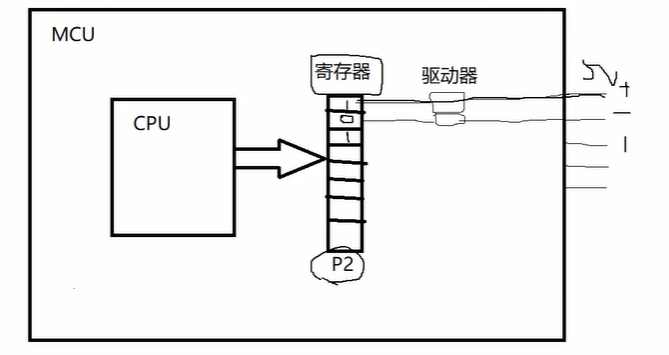
One end of the LED is connected to VCC (positive pole) and the other end is connected to the P20-P27 port of the chip. The P20-P27 port is mapped by the P2 register in the chip. When the chip outputs a high level, the LED is off, and it is on when the output is low.
If only the first LED is on, 1111 1110the lowest bit of the P2 register is assigned a value of 0 and outputs a low level, which is expressed in hexadecimal in the code
#include <REGX52.H>
void main(){


	P2 = 0xfe; // 1111 1110
	while(1){

    }
}
After the MCU executes the main function, it will execute the main again
Keil -> options for target -> output -> create hex file
The HEX file format is a file format that can be programmed into the microcontroller and executed by the microcontroller. C or assembly source files can be compiled into HEX files using different editors, such as IAR, KEIL, etc.
SCM system frequency: 12MHz, one million operations per second
Delay method generated by STC-ISP->Software Delay Calculator
#include <INTRINS.H>

void Delay500ms()		//@12.000MHz
{


	unsigned char i, j, k;

	_nop_(); // 空语句,INTRINS.H中声明
	i = 4;
	j = 205;
	k = 187;
	do
	{


		do
		{


			while (--k);
		} while (--j);
	} while (--i);
}
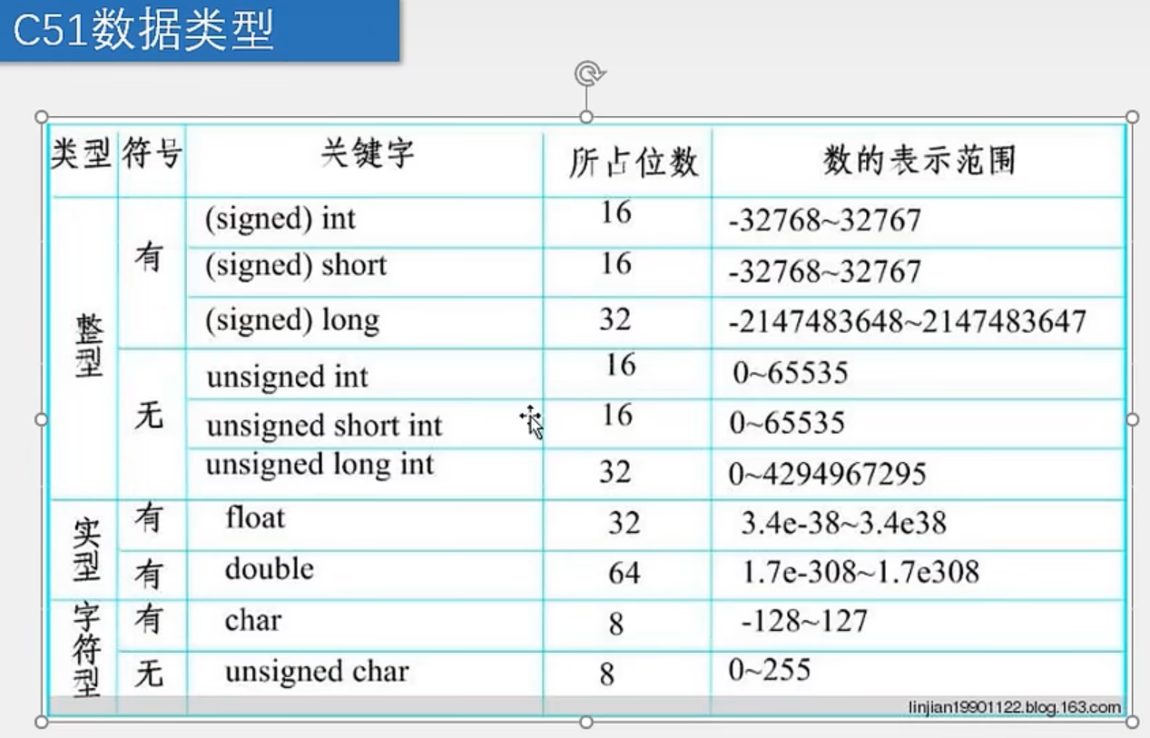
In the microcontroller, int is 16 bits (unsigned int: 0 ~ 65535 int: -32768 ~ 32767)
void Delayxms(unsigned int xms) // 指定延时时间ms
{


	unsigned char i, j;

	while(xms--){


		i = 2;
		j = 239;
		do
		{


			while (--j);
		} while (--i);
    }
}
Each register and its bits are defined in the REGX52.H header file
sfr P2      = 0xA0;
/*------------------------------------------------
P2 Bit Registers
------------------------------------------------*/
sbit P2_0 = 0xA0;
sbit P2_1 = 0xA1;
sbit P2_2 = 0xA2;
sbit P2_3 = 0xA3;
sbit P2_4 = 0xA4;
sbit P2_5 = 0xA5;
sbit P2_6 = 0xA6;
sbit P2_7 = 0xA7;
The independent button is connected to the P30-P33 port of the MCU, using the first four bits of the register P3 to map, pressing it is 0, releasing it is 1

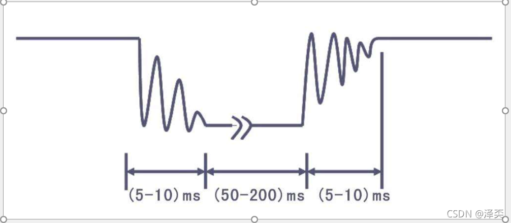
Key debounce:
Due to the elastic effect of the mechanical contact, a switch will not be stably connected immediately when it is closed, and it will not be disconnected suddenly when it is turned off, so there will be a series of vibrations when the switch is closed and disconnected.
There are two ways to debounce the keys:
- Add a line, pass this line through these circuits to perform some triggers, etc., operate through some circuits, perform some overshoot on this jitter, and then click on our microcontroller. kind of hard!
- Perform a delay function through software, and operate this debounce!
Independent button control LED display binary:
Use unsigned chartype variables to represent registers: unsigned character type (occupied by 1 byte = 8bit) just corresponds to 8-bit binary data
unsigned char p = 0;
while(1){


    if(P3_1 == 0){


        Delayxms(20);
        while(P3_1 == 0);
        Delayxms(20);

        p++;
        P2 = ~p;
    }
}
The definition of local variables should be placed on the first line of the function, and the first line should also be placed in the main function, for, while, and if. As long as the definition of local variables should be placed on the first line of the function body