Article directory
- foreword
- openGL 的 Object
- Work Phase
- Initialize vertex data into the buffer through the vertex buffer object
- Created a vertex and a fragment shader
- Link vertex data to vertex attributes in the vertex shader
- draw a single object
- Vertex Array Object VAO
- Draw a triangle (glDrawArrays function)
- Element Buffer Object EBO / Index Buffer Object IBO
- draw rectangle
- uniform
- Add color data to VAO
- Encapsulate a shader class
- expand
foreword
What is OpenGl?
- OpenGL is just a specification, and strictly speaking, it cannot be regarded as a library. Different graphics card manufacturers have slight gaps in the provision of OpenGL APIs , and the core code of OpenGL is bound to the core technology of the graphics card. Therefore, it is not open source, and it is usually used Only the API provided by the manufacturer can be operated.
- The advantage of OpenGL is that it is cross-platform, and a piece of code can run on Mac , Windows , Linux , and even mobile iOS and Android . (It is more suitable for lazy people than Direct3D , which specifically writes different APIs for different platforms . Of course, on iOS , it may be more likely to choose Apple-specific Metal ).
- As we all know, programs implemented in programming languages (C++, Java, C#) all run on the CPU , but when implementing graphics processing, in order to accurately control the GPU , it is necessary to port the code from the CPU to the GPU (the code is on the GPU. The running speed will be faster), and the shader allows us to write code on the GPU . Whether there are programmable
modern OpenGLshaders (programmable shaders) islegacy OpenGLthe main difference between and. Of course, in essence, modern OpenGL has surrendered more than old OpenGL The control is given to the programmer. - The creation of OpenGL Context (OpenGL context environment) requires some tools, such as the lightweight library GLFW (Graphics Library Framework, graphics library framework). The main function of GLFW is to create and manage windows and OpenGL contexts, and also provides basic permissions Actions - Functions that handle gamepad, keyboard, and mouse input.
review
In the last blog , the final detection of whether the configuration of the OpenGL environment is successful is achieved through a piece of code. The content about GLFW and GLAD in the code is relatively simple, so I won’t repeat it here. You can understand it through the comments in the code. If you feel that the comments are not clear, you can also learn through the article Hello .
All the code of this blog . The content of GLFW and GLAD in the code is as follows. These codes are similar to modules, almost what we must write when we want to render images and display them in the window:
#include <glad/glad.h>
#include <GLFW/glfw3.h>
#include <iostream>

// 对窗口注册一个回调函数(Callback Function),它会在每次窗口大小被调整的时候被调用。
// 参数:window - 被改变大小的窗口,width、height-窗口的新维度。
void framebuffer_size_callback(GLFWwindow* window, int width, int height)
{


    // 告诉OpenGL渲染窗口的尺寸大小,即视口(Viewport)
    // 这样OpenGL才只能知道怎样根据窗口大小显示数据和坐标
    // 调用glViewport函数来设置窗口的维度(Dimension)
    // 前两个参数控制窗口左下角的位置。第三个和第四个参数控制渲染窗口的宽度和高度(像素)
    glViewport(0, 0, width, height);
}

// 实现输入控制的函数:查询GLFW是否在此帧中按下/释放相关键,并做出相应反应
void processInput(GLFWwindow *window)
{


    // glfwGetKey两个参数:窗口,按键
    // 没有被按下返回 GLFW_PRESS
    std::cout << "是否点击ESC?" << std::endl;
    std::cout << glfwGetKey(window, GLFW_KEY_ESCAPE) << std::endl;
    if(glfwGetKey(window, GLFW_KEY_ESCAPE) == GLFW_PRESS)
        // 被按下则将 WindowShouldClose 属性置为 true
        // 以便于在关闭 渲染循环
        glfwSetWindowShouldClose(window, true);
}

const unsigned int SCR_WIDTH = 800; // 创建窗口的宽
const unsigned int SCR_HEIGHT = 600; // 创建窗口的高

int main()
{


    glfwInit(); // 初始化GLFW

    // glfwWindowHint函数的第一个参数代表选项的名称
    // 第二个参数接受一个整型,用来设置这个选项的值
    // 将主版本号(Major)和次版本号(Minor)都设为3
    glfwWindowHint(GLFW_CONTEXT_VERSION_MAJOR, 3);
    glfwWindowHint(GLFW_CONTEXT_VERSION_MINOR, 3);
    // 使用的是核心模式(Core-profile)
    glfwWindowHint(GLFW_OPENGL_PROFILE, GLFW_OPENGL_CORE_PROFILE);

#ifdef __APPLE__
    // macOS需要本语句生效 glfwWindow 的相关配置
    glfwWindowHint(GLFW_OPENGL_FORWARD_COMPAT, GL_TRUE);
#endif

    // 参数依次为:宽、高、窗口的名称,显示器用于全屏模式,设为NULL是为窗口
    // 窗口的上下文为共享资源,NULL为不共享资源
    GLFWwindow* window = glfwCreateWindow(SCR_WIDTH, SCR_HEIGHT, "FirstWindow", NULL, NULL);
    if (window == NULL)
    {


        std::cout << "Failed to create GLFW window" << std::endl;
        // 释放空间,防止内存溢出
        glfwTerminate();
        return -1;
    }

    // 创建完毕之后,需要让window的context成为当前线程的current context
    glfwMakeContextCurrent(window);
    // 窗口大小改变时视口也要随之改变,这通过对窗口注册 framebuffer_size_callback 实现。
    // 它会在每次窗口大小被调整时调用
    glfwSetFramebufferSizeCallback(window, framebuffer_size_callback);

    // glfwGetProcAddress是glfw提供的用来 加载系统相关的OpenGL函数指针地址 的函数
    // gladLoadGLLoader函数根据使用者的系统定义了正确的函数
    if (!gladLoadGLLoader((GLADloadproc)glfwGetProcAddress))
    {


        std::cout << "Failed to initialize GLAD" << std::endl;
        return -1;
    }

    /* 渲染循环(Render Loop) */
    // glfwWindowShouldClose 检查一次GLFW是否被要求退出
    // 为true时渲染循环结束
    while(!glfwWindowShouldClose(window))
    {


        // 监测键盘输入
        processInput(window);

        /* 渲染 */

        // glfwSwapBuffers 交换颜色缓冲,用来绘制并作为输出显示在屏幕
        glfwSwapBuffers(window);
        // glfwPollEvents 检查是否有触发事件
        glfwPollEvents();
    }

    glfwTerminate();

    return 0;
}
openGL 的 Object
Why does OpenGL have so many Objects?
Because the improvement goal of OpenGL is to change all the previous operations of directly passing values from the client to the server to update the Object in绑定(Bind) the video memory (in the server). Fetched Objectdata, thus avoiding a lot of inefficient data transmission. And each Objectcorresponds to a memory structure.
memory structure
- Vertex Array Object: Vertex Array Object [VAO]
- Vertex buffer object: Vertex Buffer Object [VBO]
- Element buffer object: Element Buffer Object [EBO]
- Index buffer object: Index Buffer Object [IBO]
Work Phase
Graphics Pipeline (Graphics Pipeline) refers to the process of converting a bunch of raw graphics data through a pipeline to convert 3D coordinates in OpenGL into 2D pixels that fit the screen. The process can be divided into two phases:
- Convert 3D coordinates to 2D coordinates;
- 2D coordinates are converted to colored 2D pixels.
2D coordinates are different from pixels. 2D coordinates accurately represent the position of a point in 2D space, while 2D pixels are an approximation of this point. 2D pixels are limited by the screen/window resolution.
The following figure is an abstract display of each stage of the graphics rendering pipeline, and the blue part indicates that the stage can inject a custom shader:
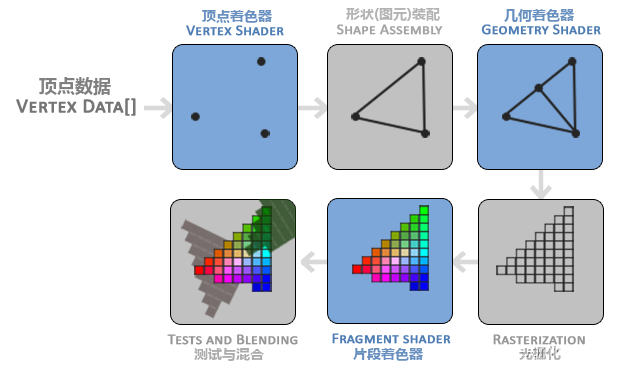
The graphics rendering pipeline is essentially a state machine, each stage will take the output of the previous stage as input, and these stages allow parallel execution .
- See below for vertex shaders.
图元装配(Primitive Assembly)The stage takes as input all the vertices output by the vertex shader (if so,GL_POINTSa vertex), and assembles all the points into the shape of the specified primitive; in the example above, a triangle.- Geometry shaders take as input a set of vertices output by the primitive assembly stage, and can generate other shapes by constructing new (or other) primitives by generating new vertices. Another triangle is generated in the example above.
光栅化阶段(Rasterization Stage)Map primitives to corresponding pixels on the final screen, generated for片段着色器(Fragment Shader)use片段(Fragment)(a fragment is all the data OpenGL needs to render a pixel). Executed before the fragment shader runs裁切(Clipping). Cropping discards all pixels outside your view to improve performance.- Fragment shaders see below.
Alpha测试And混合(Blending)the corresponding深度sum of the stage detection fragment模板(Stencil))值, use them to judge whether this pixel is in front or behind of other objects, and decide whether it should be discarded. This stage also checksalpha值(物体的透明度)and performs tests on objects混合(Blend). So, even if the output color of a pixel is calculated in the fragment shader, the final pixel color may be completely different when rendering multiple triangles.
The graphics rendering pipeline is very complex, with many configurable parts. However, for most cases, we only need to configure the vertex and fragment shaders. A geometry shader usually uses its default shader.
Initialize vertex data into the buffer through the vertex buffer object
Normalized Device Coordinates
OpenGL does not simply convert all to the screen , it only deals with standardized device coordinates [the vertex coordinates processed in the vertex shader are standardized device coordinates] , standardized device coordinates are a small space with values in . Any coordinates that fall outside the bounds are discarded/clipped and not displayed on screen. Here is a triangle defined in normalized device coordinates (ignoring the z-axis):3D坐标2D像素xyz-1.0 ~ 1.0
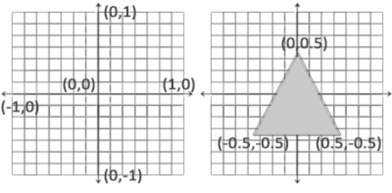
The first step in drawing a triangle is to pass the as an input to the graphics rendering pipeline in 3the form of an array , which is used to represent a triangle.3D坐标
PS: The input data in a real program is usually not standardized device coordinates, but vertex coordinates. Converting vertex coordinates to standardized device coordinates is done in the vertex shader, but this blog aims to explain it as concisely as possible rendering pipeline, so pass normalized device coordinates directly to the vertex shader.
Define an array of vertex data in normalized device coordinates (OpenGL's visible area):
float vertices[] = {


    -0.5f, -0.5f, 0.0f,
     0.5f, -0.5f, 0.0f,
     0.0f,  0.5f, 0.0f
};
verticesEach row in is a vertex (Vertex) : a collection of 3D coordinate data.verticesCalled Vertex Data (Vertex Data) : It is a collection of a series of vertices.
Since OpenGL works in 3D space, and what is rendered is a 2D triangle, the zcoordinates of the vertices are set to 0.0. In this way, the depth is the same, so that it looks like 2D.
Depth: Represents the distance between a pixel and the screen in space. If it is far away from the screen, it may be blocked by other pixels and become invisible , so it will be discarded to save resources.
Vertex Buffer Object VBO
- Vertex data is sent as input to the first processing stage of the graphics rendering pipeline: the vertex shader.
- The vertex shader will
GPUcreate memory on it to store vertex data. - The Vertex Buffer Object (
VBO) is responsible for managing thisGPUmemory (often referred to as video memory). It stores a large number of vertices in video memory, configures how OpenGL interprets this memory, and specifies how the data in video memory is sent to the graphics card.
CPUSending data from to the graphics card is relatively slow, butVBOit is possible to send a large batch of data at once, rather than once per vertex. The vertex shader can access vertices almost immediately after the data is sent to the graphics card's memory.
Next, execute the following process:
glGenBuffers
- Use
glGenBuffersthe function and a bufferIDto generate aVBOobject :
unsigned int VBO;
glGenBuffers(1, &VBO);
Function prototype:
void glGenBuffers(GLsizei n,GLuint * buffers);
n: the number of generated buffer objects;buffers: An array used to store buffer object names.- At this point only one buffer object has been generated, but the type of the buffer object is not yet determined.
glBindBuffer
- Use
glBindBuffer()to determine the type of the generated buffer object, the buffer type of the vertex buffer object isGL_ARRAY_BUFFER:
glBindBuffer(GL_ARRAY_BUFFER, VBO);
Function prototype:
void glBindBuffer(GLenum target,GLuint buffer);
target: the type of the buffer object;buffer: The name of the buffer object to bind.
官方文档指出:GL_INVALID_VALUE is generated if buffer is not a name previously returned form a call to glGenBuffers。
In other words, bufferalthough it is of GLuinttype , you cannot directly specify a constant. For example 2, if you do so, an error will GL_INVALID_VALUEappear :
OpenGL allows us to bind multiple buffer types at the same time , but requires these buffer types to be different . To give a simple example:
I want to store data into the vertex buffer, but the vertex buffer ( GL_ARRAY_BUFFER) is bound to multiple buffer objects ( VBO, VBO1, VBO2), so which buffer object to pass the data into becomes a problem.
glBufferData
- Call
glBufferDatathe function to copy the previously defined vertex data into the buffered memory:
glBufferData(GL_ARRAY_BUFFER, sizeof(vertices), vertices, GL_STATIC_DRAW);
Function prototype:
void glBufferData(GLenum target,GLsizeiptr size,const GLvoid * data,GLenum usage);
target: The type of target buffer.size: Specify the size of the transmitted data (in bytes); usesizeofto calculate the size of the vertex data.data: Specify the memory address to copy data, or if not copy dataNULL.usage: Specifies the form in which the graphics card manages the given data. There are three types:GL_STATIC_DRAW: The data will not or will hardly change.GL_DYNAMIC_DRAW: The data will be changed a lot.GL_STREAM_DRAW: The data will change each time it is plotted.
GL_DYNAMIC_DRAWand GL_STREAM_DRAWwill cause the graphics card to put the data in the memory part that can be written at high speed, and the memory space is very precious, so don't use it casually, so fill in usagethe corresponding value reasonably, and the data that will not/almost not change must be filled with GL_STATIC_DRAW.
Created a vertex and a fragment shader
What are shaders?
We found that Shader is used in some stages in the above figure , which is a small programmable program running GPUon , which quickly processes data in a specific part of the graphics rendering pipeline . Shaders have the following characteristics:
- Runs
GPUon , saving valuableCPUtime. - A shader is just a program that processes input and outputs it . Cannot communicate with each other other than input/output .
Why do you need shaders?
In fact, image processing can be done completely CPUin , and graphics rendering can be realized through serial multi-core computing. But the rendering work is very simple, just multi-point calculation. For CPUthose who deal , it is undoubtedly a waste of resources to spend a lot of time on simple rendering work.
So GPUthis hardware focused on image processing was born. It is an ultra-multi-core processor that allows parallel computing. GPUIt has hundreds of cores, which means that GPUit can Effect. (Common ones CPUmay be 4 cores, but the complexity of work that the two cores can handle is not comparable)
To sum up, OpenGL implements a specification that allows the calculation of points and pixels to be performed GPUin , which is the shader.
Shader structure
Shaders typically have the following structure:
- statement version
- input and output variables
- Uniform
- main function. The entry point of each shader is the main function, where all input variables are processed and the results are output to output variables.
// 声明版本
#version version_number
// 输入变量
in type in_variable_name;
in type in_variable_name;
// 输出变量
out type out_variable_name;
// uniform
uniform type uniform_name;
// main 函数
int main(){


  // 处理输入并进行一些图形操作
  ...
  // 输出处理过的结果到输出变量
  out_variable_name = weird_stuff_we_processed;
}
vertex shader
Because there is no default vertex/fragment shader GPUin , modern html OpenGLrequires at least one vertex shader and one fragment shader to be set up for rendering .
The main function of the vertex shader is to convert the 3D coordinates into standardized device coordinates , which are still 3D coordinates , but the value range of x, y, zis no longer the entire space, but -1.0 ~ 1.0. It also allows us to do some basic manipulation of vertex attributes.
Write a vertex shader in the shader language GLSL (OpenGL Shading Language):
# version 330 core
layout (location = 0) in vec3 aPos;

void main()
{


    gl_Position = vec4(aPos.x, aPos.y, aPos.z, 1.0);
}
version 330: GLSL version statement, in OpenGL 3.3 and later, the GLSL version number matches the OpenGL version (for example, GLSL 420 version corresponds to OpenGL 4.2).core: Kernel mode.layout (location = 0): The location value (Location) of the input variable is set , and the location data is a kind of vertex attribute.in: Keyword, declare all input vertex attributes (Input Vertex Attribute)aPosin the shader.vec3:3Afloatthree-dimensional vector with components.aPosis anvec3input variable.gl_Position: Pre-defined variable, the type isvec4,vec3hereaPosthe data of the variable is usedvec4as the parameter of the constructor, andwthe component is set as1.0f,vec.wthe component is not used to express the position in the space (we are dealing with 3D not 4D), but used in Perspective Division (Perspective Division) .
In order to be able to OpenGLuse a vertex shader, its source code must be dynamically compiled at runtime.
- Hardcodes the source code of the vertex shader in a C-style string.
const char *vertexShaderSource = "#version 330 core\n"
    "layout (location = 0) in vec3 aPos;\n"
    "void main()\n"
    "{\n"
    "   gl_Position = vec4(aPos.x, aPos.y, aPos.z, 1.0);\n"
    "}\0";
glCreateShaderCreate this shader object with , returnedunsigned intby store , so as to refer to the memory space where the shader object is located.glCreateShaderID
// glCreateShader函数参数:要创建的着色器类型
unsigned int vertexShader = glCreateShader(GL_VERTEX_SHADER);
- Attach the shader source code to the shader object, then compile it:
glShaderSource(vertexShader, 1, &vertexShaderSource, NULL);
glCompileShader(vertexShader);
glShaderSourceparameters:
GLuint shader: Specifies the handle (ID) of the shader object whose source code is to be compiledGLsizei count: Specify the number of source code strings passed, there is only one hereconst GLchar **string: An array of pointers to strings containing source codes, which is why the above code is passed in the address ofvertexShaderSourcethe pointer itself rather than the address of the string pointed to by the pointer. (because the parameter will be dereferenced twice)const GLint *length: If it is NULL, the entire string will be copied and replaced; if it is not NULL, the part with the specified length will be replaced.
glGetShaderivCheck whether the shader is compiled successfully by , and if the compilation fails, callglGetShaderInfoLogto get an error message and print it.
// 检查着色器编译错误
int success; // 定义一个整型变量来表示是否成功编译
char infoLog[512]; // 储存错误消息
glGetShaderiv(vertexShader, GL_COMPILE_STATUS, &success);
if (!success)
{


    glGetShaderInfoLog(vertexShader, 512, NULL, infoLog);
    std::cout << "ERROR::SHADER::VERTEX::COMPILATION_FAILED\n" << infoLog << std::endl;
}
glGetShaderivPrototype:
void glGetShaderiv(GLuint shader, GLenum pname, GLint *params);
shader: Specifies the shader object ID to query.pname: Specifies the inspection content, acceptable symbol names are:GL_SHADER_TYPE: It is used to judge and return the shader type, the vertex shader returnsGL_VERTEX_SHADER, and the fragment shader returnsGL_FRAGMENT_SHADER.GL_DELETE_STATUS: Determine whether the shader is deleted, return ifGL_TRUEyes, otherwise returnGL_FALSE.GL_COMPILE_STATUS: It is used to check whether the compilation is successful, if it is successfulGL_TRUE, otherwise it isGL_FALSE.GL_INFO_LOG_LENGTH: The length of the info log used to return the shader, including the null termination character (i.e. the size of the character buffer needed to store the info log). Returned if the shader has no infolog0.GL_SHADER_SOURCE_LENGTH: Returns the length of the shader source code, or returns 0 if it does not exist.
params: Because there are many kinds of results returned depending on the value of the second parameter, it is stored separately in the third parameter of the input. That's why the function return valuevoidis notGLuint.
fragment shader
片段着色器(Fragment Shader)Each fragment data, texture data, and 3D scene data (such as lighting, shadow, light color, etc.) generated by the rasterization stage can be received to calculate the final color of each rasterized blank pixel . Is where all the advanced effects of OpenGL are generated.
RGBA: red, green, blue and alpha (transparency) components, when defining a color in OpenGL or GLSL, set the intensity of each component of the color between 0.0 and 1.0. For example, if you set red to 1.0f and green to 1.0f, you will get the mixed color—yellow.
- GLSL fragment shader source code, declaring output variables:
#version 330 core
out vec4 FragColor;

void main()
{


    FragColor = vec4(1.0f, 0.5f, 0.2f, 1.0f);
}
out: Keyword, declare the output variableFragColorinto .
- hardcode
const char *fragmentShaderSource = "#version 330 core\n"
    "out vec4 FragColor;\n"
    "void main()\n"
    "{\n"
    "   FragColor = vec4(1.0f, 0.5f, 0.2f, 1.0f);\n"
    "}\n\0";
- Create shader object and record ID, attach source code, compile:
// 与顶点着色器的最大区别 glCreateShader 的参数 —— GL_FRAGMENT_SHADER
unsigned int fragmentShader = glCreateShader(GL_FRAGMENT_SHADER);
glShaderSource(fragmentShader, 1, &fragmentShaderSource, NULL);
glCompileShader(fragmentShader);
- Check whether the compilation is successful, the code is the same as the vertex shader checking part.
- Link the two shader objects into a shader program (
Shader Program) for rendering.
shader program object
A shader program object ( Shader Program Object) is a merged and finally linked version of multiple shaders.
When linking shaders into a program, the program links the output of each shader to the input of the next shader. When the output doesn't match the input, you get a connection error.
- Create a program object that
shaderProgramreceives a reference to the ID of the newly created program object:
unsigned int shaderProgram = glCreateProgram();
- Attach the previously compiled vertex/fragment shader to the shader program object and
glLinkProgramlink with :
glAttachShader(shaderProgram, vertexShader);
glAttachShader(shaderProgram, fragmentShader);
glLinkProgram(shaderProgram);
- Check whether the link is successful like checking whether the compilation is successful:
glGetProgramiv(shaderProgram, GL_LINK_STATUS, &success);
if(!success) {


    glGetProgramInfoLog(shaderProgram, 512, NULL, infoLog);
    std::cout << "ERROR::SHADER::PROGRAM::LINKING_FAILED\n" << infoLog << std::endl;
}
- After linking the shader objects to the program object , delete the shader objects , they are no longer needed, freeing the occupied memory:
glDeleteShader(vertexShader);
glDeleteShader(fragmentShader);
- Activate the shader program object :
// 将这段函数加入while循环函数的渲染部分,就可以激活这个着色器程序对象了。
glUseProgram(shaderProgram);
Link vertex data to vertex attributes in the vertex shader
Vertex buffer data is parsed as follows:
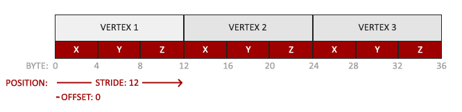
- Position data is stored as 32-bit (4-byte) floating point values.
- Each location contains 3 such values.
- There are no gaps (or other values) between these 3 values. These several values are packed closely in the array.
- The first value in the data is at the beginning of the buffer.
The code implementation corresponding to parsing vertex data:
glVertexAttribPointerSpecifies the data of the vertex attribute arrayindexwhose :
glVertexAttribPointer(0, 3, GL_FLOAT, GL_FALSE, 3 * sizeof(float), (void*)0);
Function prototype:
void glVertexAttribPointer( GLuint index, GLint size, GLenum type, GLboolean normalized, GLsizei stride,const GLvoid * pointer);
index: The index value of the vertex attribute to configure. In the vertex shaderlayout(location = 0),positionthe position value (Location) of the vertex attribute was defined using .locationThe value of0is the index value.size: Specifies the number of components for each vertex attribute, which must be 1, 2, 3 or 4. The initial value is 4. (positionFor example, it is composed of 3 components [x, y, z], while the color is 4 components [r, g, b, a]).type: Specifies the data type of each component in the array. The available symbolic constants are:GL_BYTE,GL_UNSIGNED_BYTE,GL_SHORT,GL_UNSIGNED_SHORT,GL_FIXEDandGL_FLOAT, the initial value isGL_FLOAT. In addition,GLSLinvec*is composed of floating-point values.normalized: Specifies whether fixed-point data values should be normalized [Normalize] (GL_TRUE) or directly converted to fixed-point values (GL_FALSE) when accessed. If yesGL_TRUE, all data will be mapped between0(for signedsigneddata-1)1between.stride: Specifies the offset between consecutive vertex attributes. The initial value is0, which means that the vertex attributes are closely packed together. Since the next group position data is3afterfloat, we set the step size to3 * sizeof(float). In this example there is no gap between the two vertex attributes, so it can also be set to0toOpenGLdecide what the specific step size is (only available when the values are closely packed).pointer: Specifies the offset of the first component within the first vertex attribute of the array. The array andGL_ARRAY_BUFFERbindings are stored in the buffer. The initial value is0; since the position data is at the beginning of the array, the offset is0.
Each vertex attribute obtains its data from the memory managed by a vertex buffer object, and the specific vertex buffer object (there can be multiple vertex buffer objects in the program) is obtained by binding to GL_ARRAY_BUFFER when calling glVertexAttribPointer Determined by the buffer object. Only one buffer object can be bound to GL_ARRAY_BUFFER at a time. At this time, the previously defined VBO is bound to GL_ARRAY_BUFFER, and vertex attribute 0 will be linked to its vertex data.
glEnableVertexAttribArrayEnable vertex attributes. Vertex attributes are disabled by default.
glEnableVertexAttribArray(0);
Function prototype:
void glEnableVertexAttribArray(GLuint index);

void glDisableVertexAttribArray(GLuint index);

void glEnableVertexArrayAttrib(	GLuint vaobj, GLuint index);

void glDisableVertexArrayAttrib(GLuint vaobj, GLuint index);
vaobj:glDisableVertexArrayAttribSpecifiesglEnableVertexArrayAttribthe name of the Vertex Array Object (VAO) for the and functions.index: Specifies the index (vertex attribute position value) to enable/disable.
draw a single object
At this point, all the processes are over. If you want to draw an object in OpenGL, the code will look like this:
// 0. 复制顶点数组到缓冲中供OpenGL使用
glBindBuffer(GL_ARRAY_BUFFER, VBO);
glBufferData(GL_ARRAY_BUFFER, sizeof(vertices), vertices, GL_STATIC_DRAW);

// 1. 设置顶点属性指针
glVertexAttribPointer(0, 3, GL_FLOAT, GL_FALSE, 3 * sizeof(float), (void*)0);
glEnableVertexAttribArray(0);

// 2. 当我们渲染一个物体时要使用着色器程序
glUseProgram(shaderProgram);

// 3. 绘制物体
someOpenGLFunctionThatDrawsOurTriangle();
When the number of vertex attributes is no longer 1, but many, you have to call glBufferDataand glVertexAttribPointer, many times glEnableVertexAttribArray. Binding the correct buffer objects, configuring all the vertex attributes for each object quickly became a chore.
This requires an object that can store the state configuration, and then restore the state by binding this object. It depends VAO.
Vertex Array Object VAO
Why use VAOs?
VBOThe drawing efficiency has been greatly improved, but the position coordinates, normal vectors, texture coordinates and other data of different aspects of the vertices need to be specified separately every time they are used, which repeats some unnecessary work.
The Vertex Array Object (VAO) can VBObe bound like that. When configuring the vertex attribute pointer, you only need to call will once glVertexAttribPointer, glEnableVertexAttribArrayand then when you draw the object, you only need to bind the vertex attribute pointer accordingly VAO. This makes it very simple to switch between different vertex data and attribute configurations, just by binding different ones VAO.
OpenGL's core mode requires us to use VAOs. If binding the VAO fails, OpenGL will refuse to draw anything.
What the VAO Stores
glEnableVertexAttribArrayglDisableVertexAttribArrayand calls.glVertexAttribPointerVertex attribute configuration set via .- By
glVertexAttribPointercalling the associated vertex attributeVBO.
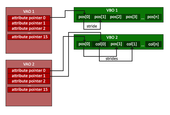
attribute pointerThe (property pointer) in the VAO points to a certain property in the VBOpos( [position] orcol[color]), as shown in the figure above, it isattribute pointer 0used toattribute pointer 1manage the position property and the color property.- For VBO , all attributes of each vertex are stored adjacently, the position ( ) and color ( ) of vertex 0, so each type will have a step size ( ).
pos[0]col[0]attribute pointerstride
The process of using VAO:
- Create a VAO , and all VBOs created after the VAO belong to this VAO .
unsigned int VAO;
glGenVertexArrays(1, &VAO);
- Bind the VAO , after the binding is successful, you should bind and configure the corresponding VBO and attribute pointer, and then unbind the VAO for reuse.
// 绑定VAO
glBindVertexArray(VAO);
When planning to draw multiple objects, first generate/configure all the VAOs (and the necessary VBOs and property pointers), then store them for later use. When drawing one of the objects, take out the corresponding VAO, bind it, and unbind the VAO after drawing the object.
Draw a triangle (glDrawArrays function)
Use glDrawArraysthe function to draw the primitive with the currently active shader, the previously defined vertex attribute configuration, and the vertex data of the VBO ( indirectly bound through the VAO ):
glUseProgram(shaderProgram);
glBindVertexArray(VAO);
glDrawArrays(GL_TRIANGLES, 0, 3);
Function prototype:
GL_APICALL void GL_APIENTRY glDrawArrays (GLenum mode, GLint first, GLsizei count);
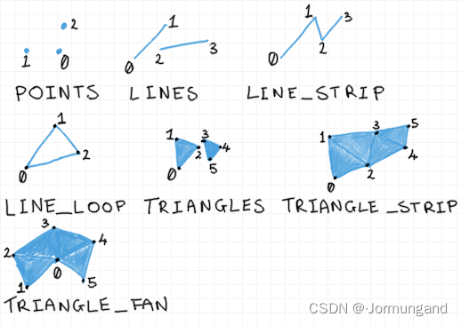
mode: Drawing method, optional values are:GL_POINTS: Treat each vertex as a point.GL_LINES: Connect every two vertices as an independent line segment, and draw N/2 line segments in total for N vertices.GL_LINE_STRIP: Draw a set of line segments connected sequentially from the first vertex to the last vertex.GL_LINE_LOOP: OnGL_LINE_STRIPthe basis of , the last vertex is connected to the first vertex.GL_TRIANGLES: Treat every three vertices as an independent triangle.GL_TRIANGLE_STRIP: Draws a set of connected triangles.GL_TRIANGLE_FAN: Draws connected triangles around the first point, with the first vertex as the vertex of all triangles.
first: From which bit in the array buffer to start drawing, usually 0.count: The number of vertices in the array.
See the full code for drawing triangles.
Element Buffer Object EBO / Index Buffer Object IBO
Element Buffer Object EBO / Index Buffer Object IBO are the same thing. Suppose you want to draw a rectangle, you can form a rectangle by drawing two triangles (OpenGL mainly deals with triangles). The set of vertices is as follows:
float vertices[] = {


    // 第一个三角形
    0.5f, 0.5f, 0.0f,   // 右上角
    0.5f, -0.5f, 0.0f,  // 右下角
    -0.5f, 0.5f, 0.0f,  // 左上角
    // 第二个三角形
    0.5f, -0.5f, 0.0f,  // 右下角
    -0.5f, -0.5f, 0.0f, // 左下角
    -0.5f, 0.5f, 0.0f   // 左上角
};
The sum is specified twice above 右下角, 左上角but a rectangle has only vertices 4instead of 6vertices, which creates 50%additional overhead. A good solution is to just store the different vertices and set the order in which they are drawn. In this way, you only need to store 4a vertex to draw a rectangle, and then you only need to specify the order of drawing. This is how Element Buffer Objects (EBOs) work.
EBOStores the index of the vertex to be drawn, ie indexed drawing (Indexed Drawing) . The process used EBOis as follows:
vertices vertex data
- First, the (unrepeated) vertices are defined, and the indices needed to draw the rectangle:
float vertices[] = {


    0.5f, 0.5f, 0.0f,   // 右上角
    0.5f, -0.5f, 0.0f,  // 右下角
    -0.5f, -0.5f, 0.0f, // 左下角
    -0.5f, 0.5f, 0.0f   // 左上角
};

unsigned int indices[] = {


    // 注意索引从0开始!
    // 此例的索引(0,1,2,3)就是顶点数组vertices的下标,
    // 这样可以由下标代表顶点组合成矩形

    0, 1, 3, // 第一个三角形
    1, 2, 3  // 第二个三角形
};
glGenBuffers
- Create an element buffer object:
unsigned int EBO;
glGenBuffers(1, &EBO);
glBufferData
- First bind the EBO and then use glBufferData to copy the index to the buffer:
glBindBuffer(GL_ELEMENT_ARRAY_BUFFER, EBO);
glBufferData(GL_ELEMENT_ARRAY_BUFFER, sizeof(indices), indices, GL_STATIC_DRAW);
glPolygonMode
- Controls how polygons are displayed, GL_LINE draws in wireframe mode.
glPolygonMode(GL_FRONT_AND_BACK, GL_LINE);
Function prototype:
void glPolygonMode(GLenum face,GLenum mode);
- face: Determines which parts of the object the display mode will apply to, controls the drawing mode for the front and back faces of polygons:
- GL_FRONT indicates that the display mode will apply to the front face of the object (that is, the face that the object can see)
- GL_BACK indicates that the display mode will apply to the back face of the object (that is, the face that cannot be seen on the object)
- GL_FRONT_AND_BACK indicates that the display mode will apply to all sides of the object
- mode: Determine how the surface of the selected object is displayed (display mode):
- GL_POINT means to display vertices, and polygons are displayed with points
- GL_LINE means to display line segments, and polygons are displayed with outlines
- GL_FILL indicates the display surface, and the polygon adopts the filling form
glDrawElements
- Replace the glDrawArrays function with glDrawElements to draw from the index buffer using the index in the currently bound index buffer object:
glDrawElements(GL_TRIANGLES, 6, GL_UNSIGNED_INT, 0);
Function prototype:
void glDrawElements
                 (GLenum mode,GLsizei count,GLenum type,const GLvoid *indices);
mode: Drawing method, sameglDrawArraysasmodeparameter in .count: The number of vertices to be drawn, two vertices in vertices are reused, so fill in here6.type: The type of index, generallyGL_UNSIGNED_INT.*indices:EBOThe offset. An index array can be passed when the index buffer object is no longer used.
VAO gives EBO
glDrawElementsThe function gets its index from the currently bound GL_ELEMENT_ARRAY_BUFFERtarget . EBOThis means that every time an object is rendered using an index, the corresponding object must be bound EBO, which is a bit of a hassle. Does this question sound familiar? Isn't this a problem that is not VAOonly VBOencountered sometimes. Coincidentally the bindings are VAOalso tracked EBO. On binding VAO, the last one bound before EBOis automatically stored VAOas EBO.
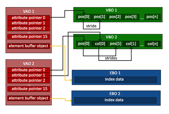
There is a small detail in the picture above: VAOonly one can be bound EBO, but multiple can be bound VBO. So make sure to unbind first EBOand then unbind VAO, otherwise VAOthere will be no EBOconfiguration, and you will not be able to draw successfully.
The binding and unbinding of OpenGL VAO VBO EBO (IBO) is worth a look.
draw rectangle
The final initialization and drawing code now looks like this:
// ..:: 初始化代码 :: ..
// 1. 绑定顶点数组对象
glBindVertexArray(VAO);
// 2. 把我们的顶点数组复制到一个顶点缓冲中,供OpenGL使用
glBindBuffer(GL_ARRAY_BUFFER, VBO);
glBufferData(GL_ARRAY_BUFFER, sizeof(vertices), vertices, GL_STATIC_DRAW);
// 3. 复制我们的索引数组到一个索引缓冲中,供OpenGL使用
glBindBuffer(GL_ELEMENT_ARRAY_BUFFER, EBO);
glBufferData(GL_ELEMENT_ARRAY_BUFFER, sizeof(indices), indices, GL_STATIC_DRAW);
// 4. 设定顶点属性指针
glVertexAttribPointer(0, 3, GL_FLOAT, GL_FALSE, 3 * sizeof(float), (void*)0);
glEnableVertexAttribArray(0);

[...]

glPolygonMode(GL_FRONT_AND_BACK, GL_LINE);

// ..:: 绘制代码(渲染循环中) :: ..
glUseProgram(shaderProgram);
glBindVertexArray(VAO); // 如果绘制多个对象,在这里切换绑定VAO
glDrawElements(GL_TRIANGLES, 6, GL_UNSIGNED_INT, 0);
glBindVertexArray(0);
See the full code for drawing rectangles.
uniform
UniformIs CPUanother GPUway to send data from the application in it to the shader in it, in addition to vertex attributes. Its characteristics are as follows:
uniformIs global , meaning thatuniformthe variable must be unique within each shader program object, and it can be accessed by any shader of the shader program at any stage.- No matter
uniformwhat the value is set to,uniformthe data will be kept until the old data is reset or updated.
For example, by uniformsetting the color of the triangle:
#version 330 core
out vec4 FragColor;
uniform vec4 ourColor; // 在OpenGL程序代码中设定这个变量
void main(){


    FragColor = ourColor;
}
If you declare a uniformbut GLSLdon't use it in the code, the compiler will silently remove the variable, resulting in it not being included in the final compiled version, which can lead to several very troublesome errors!
Before adding data to it, we first need to find the index/position value of the attribute uniformin the shader . Is a similar input data, before the external data is bound by the index value , and it is not needed at all , but by the name of the shader program object and :uniformuniforminlayout (location = 0) in vec3 aPoslocation = 0uniformlayoutuniform
/* 在循环渲染的代码块中加入下列代码 */
// 获取运行的秒数
float timeValue = glfwGetTime();
// 通过sin函数让颜色在0.0到1.0之间改变,最后将结果储存到greenValue里。
float greenValue = (sin(timeValue) / 2.0f) + 0.5f;
// 通过glGetUniformLocation查询uniform ourColor的位置值,返回-1代表没有找到。
int vertexColorLocation = glGetUniformLocation(shaderProgram, "ourColor");
glUseProgram(shaderProgram);
// 通过glUniform4f函数设置uniform值
glUniform4f(vertexColorLocation, 0.0f, greenValue, 0.0f, 1.0f);
Note that uniforma previously used shader program (call glUseProgram) is not required to look up an address, but a program must be used before updating one uniform(call glUniform4f), since the settings uniformare made in the currently active shader program.
glGetUniformLocation
GLint glGetUniformLocation(GLuint program, const GLchar *name);
program: Specifies the shader program object to query.name: Points to an unterminated string containinguniformthe name of the variable whose position is to be queried.
glUniform4f
OpenGLIts core is a Clibrary, so type overloading is not supported, and new functions must be defined for different function parameters; glUniformit is a typical example. This function has a specific suffix that identifies uniformthe type of setting. Possible suffixes are:

In the above example, the data is passed through ( versions can also be used) since each value needs to be uniformset separately.4floatglUniform4fglUniformfv
The code for drawing a color-changing triangle can be found here.
Add color data to VAO
Color data is stored in VAO
Color is one of the vertex attributes, so it can also be stored in VAO. Try storing the color data in a VAO and passing it to the vertex shader instead of the fragment shader.
float vertices[] = {


    // 位置              // 颜色
     0.5f, -0.5f, 0.0f,  1.0f, 0.0f, 0.0f,   // 右下 红色
    -0.5f, -0.5f, 0.0f,  0.0f, 1.0f, 0.0f,   // 左下 绿色
     0.0f,  0.5f, 0.0f,  0.0f, 0.0f, 1.0f    // 顶部 蓝色
};
Since there is now more data to be sent to the vertex shader, it is necessary to adjust the vertex shader to accept the color value as an input to the vertex attribute. Use layoutthe identifier to aColorset the positional value of the attribute as 1:
const char *vertexShaderSource = "#version 330 core\n"
    "layout (location = 0) in vec3 point;\n"
    "layout (location = 1) in vec3 color;\n"
    "out vec3 ourColor;\n"
    "void main()\n"
    "{\n"
    "   gl_Position = vec4(point.x, point.y, point.z, 1.0);\n"
    "   ourColor = color;\n"
    "}\0";
Adding new vertex attributes (colors) requires updating VBOmemory and reconfiguring vertex attribute pointers. VBOThe data in the updated memory is shown in the figure below:

Knowing the current layout, you can use glVertexAttribPointerthe function to update the vertex format:
// 位置
glVertexAttribPointer(0, 3, GL_FLOAT, GL_FALSE, 6 * sizeof(float), (void*)0);
glEnableVertexAttribArray(0); // 启用layout 0

// 颜色
glVertexAttribPointer(1, 3, GL_FLOAT, GL_FALSE, 6 * sizeof(float), (void*)(3 * sizeof(float)));
glEnableVertexAttribArray(1); // 启用layout 1
Linkage of vertex shader and fragment shader
At this time, it is no longer used uniformto pass the color of the fragment, but the output of the vertex shader is used ourColoras the input of the fragment shader:
const char *fragmentShaderSource = "#version 330 core\n"
    "out vec4 FragColor;\n"
    "in vec3 ourColor;\n"
    "void main()\n"
    "{\n"
    "   FragColor = vec4(ourColor, 1.0f);\n"
    "}\n\0";
draw a three-color triangle
The result of the program running is as follows:
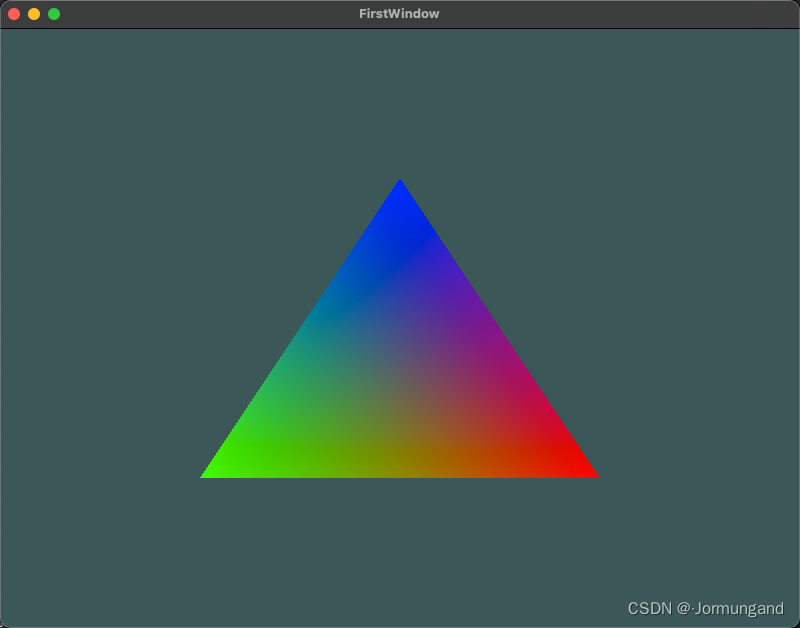
Huh? The running results seem to be different from the design expectations. Logically speaking, it should be a triangle with pure three colors of red, green and blue. How come the colors at the three corners are quite pure, and the closer to the center of the triangle, the more mixed the colors are? This is due to fragment interpolation in the fragment shader .
When rendering a triangle, the rasterization stage usually subdivides the area divided by the geometry shader into more fragments. The raster is interpolated based on where each fragment is on the triangle . For example, there is a line segment, the upper endpoint is green, and the lower endpoint is blue. If a fragment shader 70%is running at the position of the line segment (near the green end), its color input attribute will be 30%blue+ 70%green.
The image above has 3 vertices and corresponding 3 colors. From the perspective of the pixels of this triangle, it may contain about 50,000 fragments. The fragment shader interpolates colors for these pixels. If you look closely at the colors it should be clear: red first turns purple and then blue. Fragment interpolation is applied to all input attributes of the fragment shader.
Encapsulate a shader class
Writing, compiling, and managing shaders is a hassle. Let's write a class that reads shaders from disk, compiles and links them, and checks them for errors. Come on, encapsulate what you have learned so far into an abstract object!
Put all the shader classes in the header file to facilitate porting. First add the necessary include and define the class structure:
#ifndef SHADER_H
#define SHADER_H

#include <glad/glad.h>; // 包含glad来获取所有的必须OpenGL头文件

#include <string>
#include <fstream>
#include <sstream>
#include <iostream>

class Shader{


public:
    // 着色器程序ID
    unsigned int ID;

    // 构造函数从文件路径读取顶点/片段着色器源代码以构建着色器
    Shader(const char* vertexPath, const char* fragmentPath);
    // 使用/激活程序
    void use();
    // uniform工具函数
    void setBool(const std::string &name, bool value) const;
    void setInt(const std::string &name, int value) const;
    void setFloat(const std::string &name, float value) const;
private:
    // 用于检查着色器编译/链接错误的实用程序函数
    void checkCompileErrors(unsigned int index, std::string type){


        int success;
        char infoLog[1024];
        if (type != "PROGRAM")
        {


            glGetShaderiv(index, GL_COMPILE_STATUS, &success);
            if (!success)
            {


                glGetShaderInfoLog(index, 1024, NULL, infoLog);
                std::cout << "ERROR::SHADER_COMPILATION_ERROR of type: " << type << "\n" << infoLog << std::endl;
            }
        }
        else
        {


            glGetProgramiv(index, GL_LINK_STATUS, &success);
            if (!success)
            {


                glGetProgramInfoLog(index, 1024, NULL, infoLog);
                std::cout << "ERROR::PROGRAM_LINKING_ERROR of type: " << type << "\n" << infoLog << std::endl;
            }
        }
    }
};

#endif
Constructor
Shader(const char* vertexPath, const char* fragmentPath){


    // 1. 从文件路径中获取顶点/片段着色器
    std::string vertexCode;
    std::string fragmentCode;
    std::ifstream vShaderFile;
    std::ifstream fShaderFile;
    // 保证ifstream对象可以抛出异常:
    vShaderFile.exceptions(std::ifstream::failbit | std::ifstream::badbit);
    fShaderFile.exceptions(std::ifstream::failbit | std::ifstream::badbit);
    try
    {


        // 打开文件
        vShaderFile.open(vertexPath);
        fShaderFile.open(fragmentPath);
        std::stringstream vShaderStream, fShaderStream;
        // 读取文件的缓冲内容到数据流中
        vShaderStream << vShaderFile.rdbuf();
        fShaderStream << fShaderFile.rdbuf();
        // 关闭文件流
        vShaderFile.close();
        fShaderFile.close();
        // 转换数据流到string
        vertexCode   = vShaderStream.str();
        fragmentCode = fShaderStream.str();
    }
    catch(std::ifstream::failure e)
    {


        std::cout << "ERROR::SHADER::FILE_NOT_SUCCESFULLY_READ" << std::endl;
    }
    const char* vShaderCode = vertexCode.c_str();
    const char* fShaderCode = fragmentCode.c_str();

    // 2. 编译着色器
    unsigned int vertex, fragment;

    // 顶点着色器
    vertex = glCreateShader(GL_VERTEX_SHADER);
    glShaderSource(vertex, 1, &vShaderCode, NULL);
    glCompileShader(vertex);
    checkCompileErrors(vertex, "VERTEX");
    // 片段着色器也类似
    fragment = glCreateShader(GL_FRAGMENT_SHADER);
    glShaderSource(fragment, 1, &fShaderCode, NULL);
    glCompileShader(fragment);
    checkCompileErrors(fragment, "FRAGMENT");

    // 着色器程序
    ID = glCreateProgram();
    glAttachShader(ID, vertex);
    glAttachShader(ID, fragment);
    glLinkProgram(ID);
    checkCompileErrors(ID, "PROGRAM");

    // 删除着色器,它们已经链接到我们的程序中了,已经不再需要了
    glDeleteShader(vertex);
    glDeleteShader(fragment);
}
use function
void use()
{


    glUseProgram(ID);
}
Uniform's set function
void setBool(const std::string &name, bool value) const{


    glUniform1i(glGetUniformLocation(ID, name.c_str()), (int)value);
}
void setInt(const std::string &name, int value) const{


    glUniform1i(glGetUniformLocation(ID, name.c_str()), value);
}
void setFloat(const std::string &name, float value) const{


    glUniform1f(glGetUniformLocation(ID, name.c_str()), value);
}
use
Introduce Shader.hthe header file to simplify the code, take the code of the three-color triangle as an example:
#include <glad/glad.h>
#include <GLFW/glfw3.h>
#include <iostream>
#include <cmath>
#include "Shader.h"

using namespace std;

// 对窗口注册一个回调函数(Callback Function),它会在每次窗口大小被调整的时候被调用。
// 参数:window - 被改变大小的窗口,width、height-窗口的新维度。
void framebuffer_size_callback(GLFWwindow* window, int width, int height)
{


    // 告诉OpenGL渲染窗口的尺寸大小,即视口(Viewport)
    // 这样OpenGL才只能知道怎样根据窗口大小显示数据和坐标
    // 调用glViewport函数来设置窗口的维度(Dimension)
    // 前两个参数控制窗口左下角的位置。第三个和第四个参数控制渲染窗口的宽度和高度(像素)
    glViewport(0, 0, width, height);
}

// 实现输入控制的函数:查询GLFW是否在此帧中按下/释放相关键,并做出相应反应
void processInput(GLFWwindow *window)
{


    // glfwGetKey两个参数:窗口,按键
    // 没有被按下返回 GLFW_PRESS
    if(glfwGetKey(window, GLFW_KEY_ESCAPE) == GLFW_PRESS)
        // 被按下则将 WindowShouldClose 属性置为 true
        // 以便于在关闭 渲染循环
        glfwSetWindowShouldClose(window, true);
}

const unsigned int SCR_WIDTH = 800; // 创建窗口的宽
const unsigned int SCR_HEIGHT = 600; // 创建窗口的高

int main(){


    glfwInit(); // 初始化GLFW

    // glfwWindowHint函数的第一个参数代表选项的名称
    // 第二个参数接受一个整型,用来设置这个选项的值
    // 将主版本号(Major)和次版本号(Minor)都设为3
    glfwWindowHint(GLFW_CONTEXT_VERSION_MAJOR, 3);
    glfwWindowHint(GLFW_CONTEXT_VERSION_MINOR, 3);
    // 使用的是核心模式(Core-profile)
    glfwWindowHint(GLFW_OPENGL_PROFILE, GLFW_OPENGL_CORE_PROFILE);

#ifdef __APPLE__
    // macOS需要本语句生效 glfwWindow 的相关配置
    glfwWindowHint(GLFW_OPENGL_FORWARD_COMPAT, GL_TRUE);
#endif

    // 参数依次为:宽、高、窗口的名称,显示器用于全屏模式,设为NULL是为窗口
    // 窗口的上下文为共享资源,NULL为不共享资源
    GLFWwindow* window = glfwCreateWindow(SCR_WIDTH, SCR_HEIGHT, "FirstWindow", NULL, NULL);
    if (window == NULL)
    {


        std::cout << "Failed to create GLFW window" << std::endl;
        // 释放空间,防止内存溢出
        glfwTerminate();
        return -1;
    }

    // 创建完毕之后,需要让window的context成为当前线程的current context
    glfwMakeContextCurrent(window);
    // 窗口大小改变时视口也要随之改变,这通过对窗口注册 framebuffer_size_callback 实现。
    // 它会在每次窗口大小被调整时调用
    glfwSetFramebufferSizeCallback(window, framebuffer_size_callback);

    // glfwGetProcAddress是glfw提供的用来 加载系统相关的OpenGL函数指针地址 的函数
    // gladLoadGLLoader函数根据使用者的系统定义了正确的函数
    if (!gladLoadGLLoader((GLADloadproc)glfwGetProcAddress))
    {


        std::cout << "Failed to initialize GLAD" << std::endl;
        return -1;
    }

    /* 设置顶点数据(和缓冲区)并配置顶点属性 */
    float vertices[] = {


        // 位置              // 颜色
         0.5f, -0.5f, 0.0f,  1.0f, 0.0f, 0.0f,   // 右下 红色
        -0.5f, -0.5f, 0.0f,  0.0f, 1.0f, 0.0f,   // 左下 绿色
         0.0f,  0.5f, 0.0f,  0.0f, 0.0f, 1.0f    // 顶部 蓝色
    };

    // build and compile our shader program
    Shader ourShader("3.3.shader.vs", "3.3.shader.fs"); // you can name your shader files however you like

    unsigned int VBOs[2], VAOs[2];
    glGenVertexArrays(2, VAOs);
    glGenBuffers(2, VBOs); // 生成2个 VBO 对象

    /* 首先绑定顶点数组对象,然后绑定并设置顶点缓冲区,然后配置顶点属性。 */
    glBindVertexArray(VAOs[0]);

    glBindBuffer(GL_ARRAY_BUFFER, VBOs[0]); // 确定生成的缓冲对象的类型
    // 把顶点数据复制到缓冲的内存中
    glBufferData(GL_ARRAY_BUFFER, sizeof(vertices), vertices, GL_STATIC_DRAW);

    // layout(location=0), 每个顶点的pos属性(vec*)由3个组件构成,
    //(vec*)中的值的类型为GL_FLOAT, 转换为固定点值, 第一个组件的偏移量为0
    // 位置
    glVertexAttribPointer(0, 3, GL_FLOAT, GL_FALSE, 6 * sizeof(float), (void*)0);
    glEnableVertexAttribArray(0); // 启用layout 0

    // 颜色
    glVertexAttribPointer(1, 3, GL_FLOAT, GL_FALSE, 6 * sizeof(float), (void*)(3 * sizeof(float)));
    glEnableVertexAttribArray(1); // 启用layout 1

    /* 渲染循环(Render Loop) */
    // glfwWindowShouldClose 检查一次GLFW是否被要求退出
    // 为true时渲染循环结束
    while(!glfwWindowShouldClose(window))
    {


        // 监测键盘输入
        processInput(window);

        /* 渲染 */
        // 状态设置函数,设置清空屏幕所用的颜色
        glClearColor(0.2f, 0.3f, 0.3f, 1.0f);
        // 状态使用函数,使用设定好的颜色来清除旧的颜色缓冲
        glClear(GL_COLOR_BUFFER_BIT);

        // 上面两种函数起到的作用也可以用 glClearBufferfv 来现实
        /*GLfloat color[] = {0.2, 0.3, 0.3, 1.0};
        glClearBufferfv(GL_COLOR, 0, color);*/
        ourShader.use();
        glBindVertexArray(VAOs[0]);
        glDrawArrays(GL_TRIANGLES, 0, 3);

        // glfwSwapBuffers 交换颜色缓冲,用来绘制并作为输出显示在屏幕
        glfwSwapBuffers(window);
        // glfwPollEvents 检查是否有触发事件
        glfwPollEvents();
    }

    // 可选:一旦所有资源超出其用途,则取消分配:
    glDeleteVertexArrays(2, VAOs);
    glDeleteBuffers(2, VBOs);

    glfwTerminate();

    return 0;
}
expand
make the triangle upside down
To make a triangle upside down, what else can I think of besides modifying the vertex array? Modify the vertex shader source code!
#version 330 core
layout (location = 0) in vec3 aPos;
layout (location = 1) in vec3 aColor;

out vec3 ourColor;

void main(){


    // just add a - to the y position
    gl_Position = vec4(aPos.x, -aPos.y, aPos.z, 1.0);
    ourColor = aColor;
}
moving triangle
Use to uniformdefine a horizontal offset, which can be used in the vertex shader to achieve the movement of the triangle.
// In Render Loop of your CPP file :
float offset = 0.5f;
ourShader.setFloat("xOffset", offset);

// In your vertex shader code file:
#version 330 core
layout (location = 0) in vec3 aPos;
layout (location = 1) in vec3 aColor;

out vec3 ourColor;

uniform float xOffset;

void main()
{


    // add the xOffset to the x position of the vertex position
    gl_Position = vec4(aPos.x + xOffset, aPos.y, aPos.z, 1.0);
    ourColor = aColor;
}