1. Draw point GL_POINTS
The point size that OpenGL draws by default is 1px, you can use glPointSize() to change the size of the point, but pay attention: glPointSize() cannot be placed between glBegin() and glEnd(), it must be placed before glBegin().
1. Code
void Draw()
{
    glClearColor(1, 1, 1, 1.0f);  //白色背景
    glClear(GL_COLOR_BUFFER_BIT);
    //绘制点
    glPointSize(10.0f);
    glBegin(GL_POINTS);

    glColor4ub(255, 0, 0, 255);
    glVertex3d(-0.2f, 0, -1.5f);

    glColor4ub(0, 255, 0, 255);
    glVertex3d(-0.1f, 0, -1.5f);

    glColor4ub(0, 0, 255, 255);
    glVertex3d(-0.0f, 0, -1.5f);

    glEnd();
}
2. Drawing effect
2. Draw the line
1.GL_LINES
A set of straight lines can be obtained by connecting each pair of adjacent points ( two are a pair, which cannot be reused ). If the last endpoint is in an odd position, the point is ignored.
(1) Code
void Draw()
{
    glClearColor(1, 1, 1, 1.0f);  //白色背景
    glClear(GL_COLOR_BUFFER_BIT);

    //绘制线
    glLineWidth(10.0f);
    glBegin(GL_LINES);
    glColor4ub(255, 0, 0, 255);//红
    glVertex3f(-0.4f, 0.0f, -1.5f);

    glColor4ub(0, 255, 0, 255);//绿
    glVertex3f(0.0f, 0.0f, -1.5f);

    glColor4ub(0, 0, 255, 255);//蓝
    glVertex3f(0.0f, 0.2f, -1.5f);

    glColor4ub(0, 255, 255, 255);//青
    glVertex3f(0.0f, 0.4f, -1.5f);
    glEnd();
}
(2) Effect
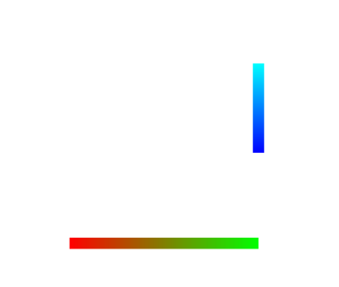
2.GL_LINE_STRIP
The incoming points will be connected sequentially until the last endpoint.
(1) Code
void Draw()
{
    glClearColor(1, 1, 1, 1.0f);  //白色背景
    glClear(GL_COLOR_BUFFER_BIT);

    //绘制线
    glLineWidth(10.0f);
    glBegin(GL_LINE_STRIP);
    glColor4ub(255, 0, 0, 255);//红
    glVertex3f(-0.4f, 0.0f, -1.5f);

    glColor4ub(0, 255, 0, 255);//绿
    glVertex3f(0.0f, 0.0f, -1.5f);

    glColor4ub(0, 0, 255, 255);//蓝
    glVertex3f(0.0f, 0.2f, -1.5f);

    glColor4ub(0, 255, 255, 255);//青
    glEnd();
}
(2) Effect
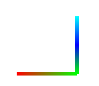
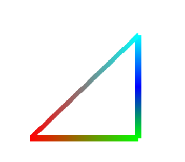
3.GL_LINE_LOOP
On the basis of GL_LINE_STRIP, end-to-end connection is carried out.
(1) Code
void Draw()
{
    glClearColor(1, 1, 1, 1.0f);  //白色背景
    glClear(GL_COLOR_BUFFER_BIT);

    //绘制线
    glLineWidth(10.0f);

    glBegin(GL_LINE_LOOP);
    glColor4ub(255, 0, 0, 255);//红
    glVertex3f(-0.4f, 0.0f, -1.5f);

    glColor4ub(0, 255, 0, 255);//绿
    glVertex3f(0.0f, 0.0f, -1.5f);

    glColor4ub(0, 0, 255, 255);//蓝
    glVertex3f(0.0f, 0.2f, -1.5f);

    glColor4ub(0, 255, 255, 255);//青
    glVertex3f(0.0f, 0.4f, -1.5f);
    glEnd();
}
(2) Effect
3. Draw a quadrilateral
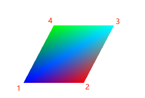
1.GL_QUADS
Note the difference from GL_TRIANGLE_STRIP.
(1) Code
void Draw()
{
    glClearColor(1, 1, 1, 1.0f);  //白色背景
    glClear(GL_COLOR_BUFFER_BIT);

    glBegin(GL_QUADS);
    glColor4ub(0, 0, 255, 255);   //蓝
    glVertex3f(-0.2f, -0.2f, -1.5f);

    glColor4ub(255, 0, 0, 255);   //红
    glVertex3f(0.2f, -0.2f, -1.5f);

    glColor4ub(0, 255, 255, 255);   //青
    glVertex3f(0.4f, 0.2f, -1.5f);

    glColor4ub(0, 255, 0, 255);   //绿
    glVertex3f(0.0f, 0.2f, -1.5f);

    glEnd();
}
(2) Effect
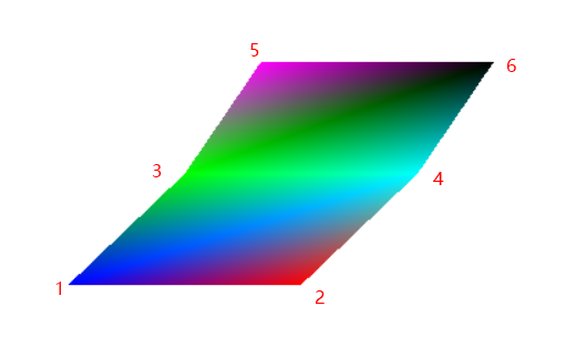
2.GL_QUAD_STRIP
Draws a set of connected quadrilaterals. Each quadrilateral is defined by a pair of vertices followed by a given pair of vertices. A total of N/2-1 quads are drawn. NOTE: The order of vertices used to construct quads from GL_QUAD_STRIP is different from the order used by GL_QUADS.
(1) Code
void Draw()
{
    glClearColor(1, 1, 1, 1.0f);  //白色背景
    glClear(GL_COLOR_BUFFER_BIT);

    glBegin(GL_QUAD_STRIP);
    glColor4ub(0, 0, 255, 255);   //蓝
    glVertex3f(-0.2f, -0.2f, -1.5f);

    glColor4ub(255, 0, 0, 255);   //红
    glVertex3f(0.2f, -0.2f, -1.5f);

    glColor4ub(0, 255, 0, 255);   //绿
    glVertex3f(0.0f, 0.0f, -1.5f);

    glColor4ub(0, 255, 255, 255);   //青
    glVertex3f(0.4f, 0.0f, -1.5f);

    glColor4ub(255, 0, 255, 255);   //粉
    glVertex3f(0.13f, 0.2f, -1.5f);

    glColor4ub(0, 0, 0, 255);   //黑
    glVertex3f(0.53f, 0.2f, -1.5f);

    glEnd();
}
(2) Effect
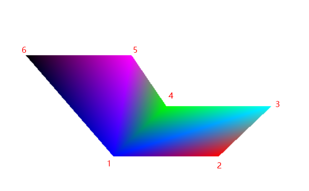
Fourth, draw a convex polygon GL_POLYGON
Draws a single convex polygon. Vertices 1 through N define this polygon.
1. Code
void Draw()
{
    glClearColor(1, 1, 1, 1.0f);  //白色背景
    glClear(GL_COLOR_BUFFER_BIT);

    glBegin(GL_POLYGON);
    glColor4ub(0, 0, 255, 255);   //蓝
    glVertex3f(-0.2f, -0.2f, -1.5f);

    glColor4ub(255, 0, 0, 255);   //红
    glVertex3f(0.2f, -0.2f, -1.5f);

    glColor4ub(0, 255, 255, 255);   //青
    glVertex3f(0.4f, 0.0f, -1.5f);

    glColor4ub(0, 255, 0, 255);   //绿
    glVertex3f(0.0f, 0.0f, -1.5f);

    glColor4ub(255, 0, 255, 255);   //粉
    glVertex3f(-0.13f, 0.2f, -1.5f);

    glColor4ub(0, 0, 0, 255);   //黑
    glVertex3f(-0.53f, 0.2f, -1.5f);

    glEnd();
}
2. Effect
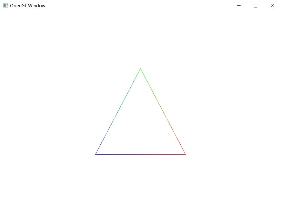
5. Draw wireframe glPolygonMode
1. Draw the wireframe
Add glPolygonMode(GL_FRONT, GL_LINE) before glBegin(); to open the wireframe mode. (glPolygonMode defaults to GL_FILL mode)
(1) Code
void Draw()
{
    glPolygonMode(GL_FRONT, GL_LINE);
    glBegin(GL_TRIANGLES);        //注意是逆时针绘制(CCW),可以通过   glFrontFace(GL_CW); 改成顺时针绘制

    glColor4ub(0, 0, 255, 255);   //蓝
    glVertex3f(-0.2f, -0.2f, -1.0f);

    glColor4ub(255, 0, 0, 255);   //红
    glVertex3f(0.2f, -0.2f, -1.0f);

    glColor4ub(0, 255, 0, 255);   //绿
    glVertex3f(0.0f, 0.2f, -1.0f);
    glEnd();
}
(2) Effect
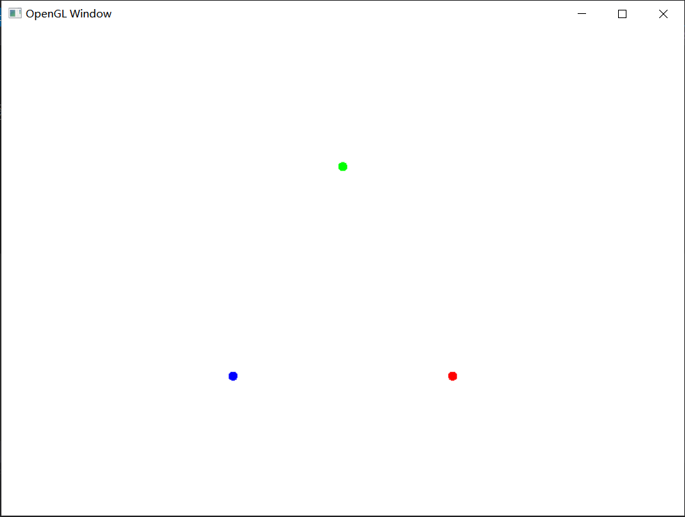
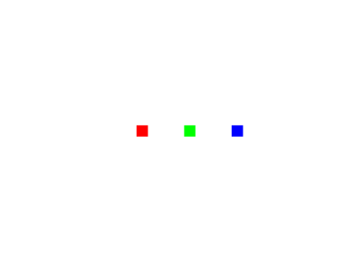
2. Draw points
In addition to using the default fill mode and wireframe mode when drawing graphics, you can also use the point mode (the default point is a rectangle, we can change it to a circle).
(1) Code
void Draw()
{
    glPolygonMode(GL_FRONT, GL_POINT);
    glPointSize(10.0f);           //点大小
    glEnable(GL_POINT_SMOOTH);    //点圆滑效果
    glBegin(GL_TRIANGLES);        //注意是逆时针绘制(CCW),可以通过   glFrontFace(GL_CW); 改成顺时针绘制

    glColor4ub(0, 0, 255, 255);   //蓝
    glVertex3f(-0.2f, -0.2f, -1.0f);

    glColor4ub(255, 0, 0, 255);   //红
    glVertex3f(0.2f, -0.2f, -1.0f);

    glColor4ub(0, 255, 0, 255);   //绿
    glVertex3f(0.0f, 0.2f, -1.0f);
    glEnd();
}
(2) Effect