
Device: 1. STM32F103C8T6 (¥17.3)
2. Zhongjing Garden 0.96-inch OLED display screen (¥9)
3. MPU6050 (¥6.4) purchased by Xintai Microelectronics
4. For ST-LINK V2 (imported chip version, ¥19.8), you must buy a firmware upgradeable version to save a lot of trouble.
Note: The program may run normally under STM32CubeIDE, but there is no response to the problem when it is powered on alone. After power-on alone, press the reset button on the board to run normally.
Link: https://pan.baidu.com/s/1cY1azrTi9-uVb5Oh9iWdEg?pwd=8888
Extraction code: 8888
1. STM32CubeIDE configuration

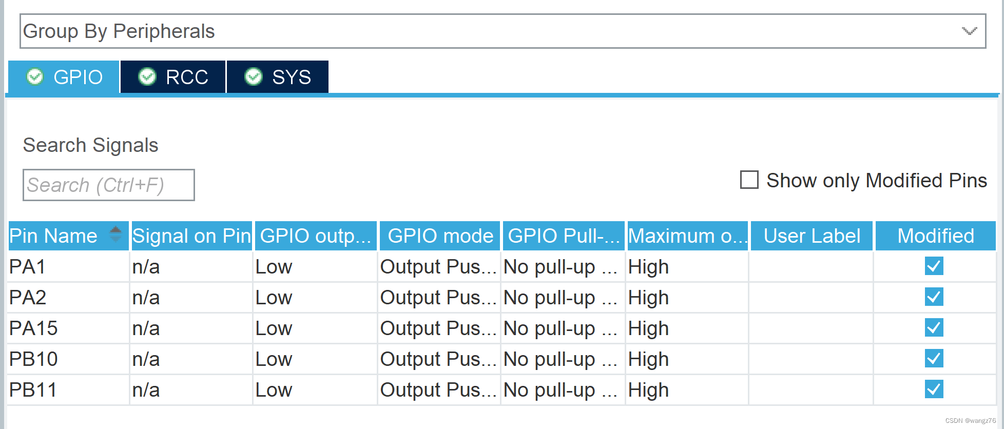 The actual PA15 is not used
PA1 and PA2 are used for IIC communication of OLED
PA10 and PA11 are used for IIC communication of MPU6050
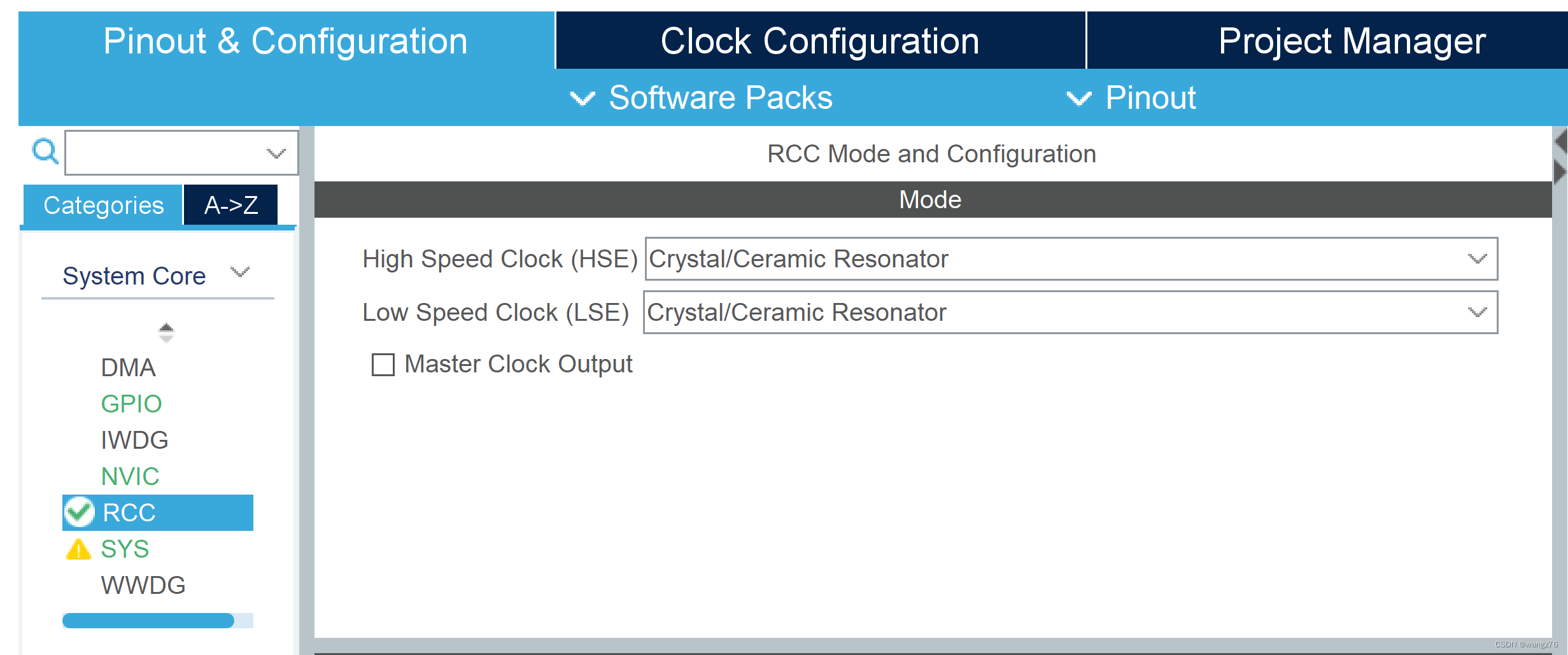

Use an external clock, or use an internal clock, but the speed is slower and the accuracy is lower.
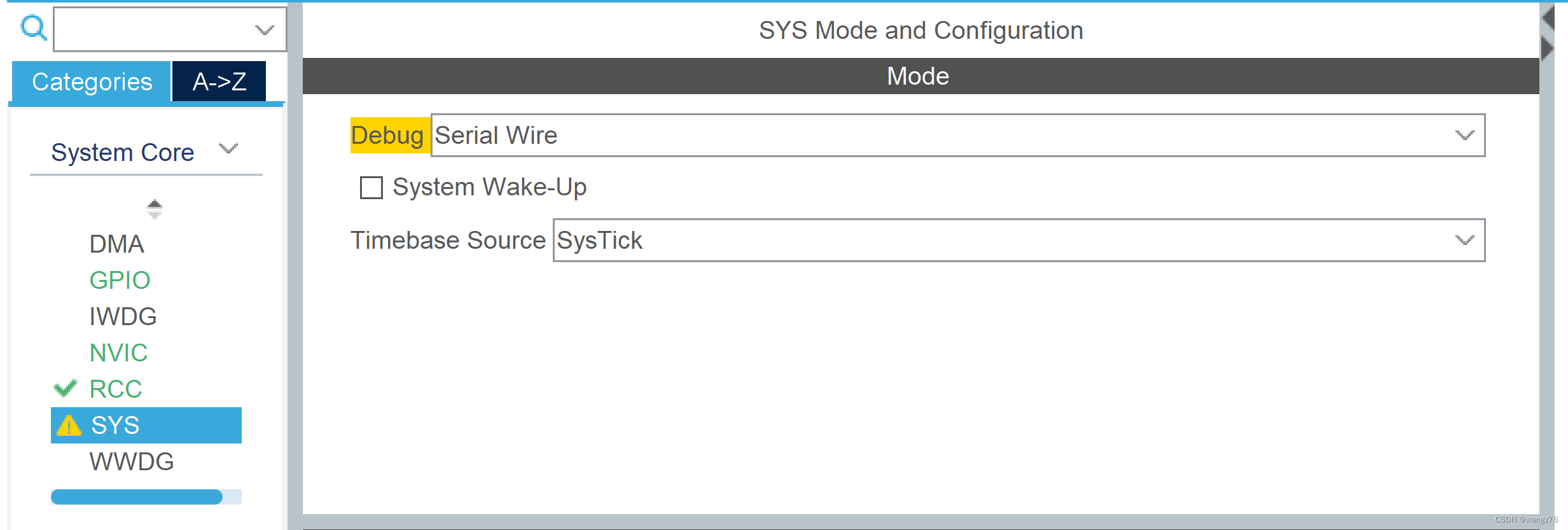
Debug port settings

How to wire: ②④⑥⑧The wiring corresponds to the corresponding port of the STM32F103C8T6 minimum system.
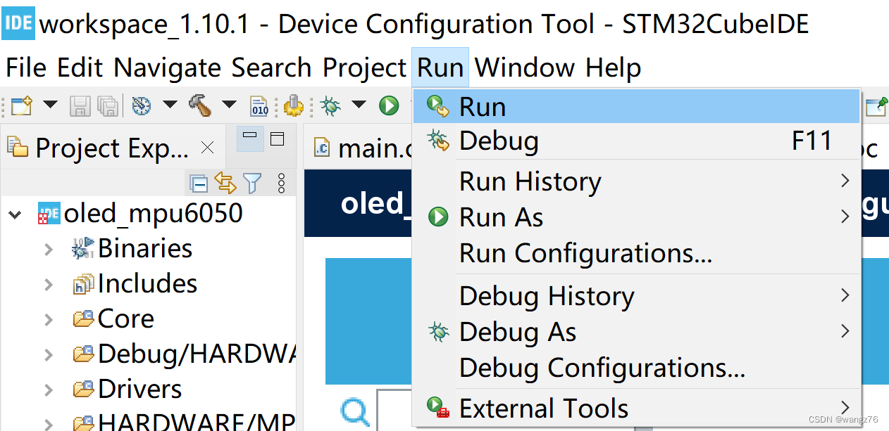
Clicking Run will write the firmware to the STM32. During this period, you may be prompted to upgrade the ST-LINK. If you do not upgrade, you will not be able to use it. With ST-LINK, it is very convenient to debug and execute step by step.

How to add external libraries

Right click project
 Add the includes folder, confirm and exit. Right-click the project and refresh it.
 After the project is refreshed, add source location and folder.
2. Use of OLED
(There are a lot of articles in the world. The drivers on the Internet are basically the same, but it is difficult to find one that uses the HAL library. We only need to change the standard library program to the HAL library. It is recommended to figure out the basic principles of IIC.)
The source code is in the Baidu link, here is where I modified it, the original source code is only commented out, not deleted, it is easy to identify.
olediic.h, keep the original function unchanged as much as possible, and the program modification is the least.
#ifndef __IIC_H
#define __IIC_H
//#include "sys.h"
#include "stm32f1xx_hal.h"
#define u8 uint8_t
#define u32 uint32_t
#define u16 uint16_t
/************** *
Note: When simulating IIC, any IO port (except JTAG port, can be used as SDA and SCL)
*****************/
//#define OLED_SCL_Clr() GPIO_ResetBits(GPIOA, GPIO_Pin_1)//SCL
#define OLED_SCL_Clr() HAL_GPIO_WritePin(GPIOA,GPIO_PIN_1,GPIO_PIN_RESET)
//#define OLED_SCL_Set() GPIO_SetBits(GPIOA,GPIO_Pin_1)
#define OLED_SCL_Set() HAL_GPIO_WritePin(GPIOA_SET1,GPIO_P)
//#define OLED_SDA_Clr() GPIO_ResetBits(GPIOA,GPIO_Pin_2)//AIN
#define OLED_SDA_Clr() HAL_GPIO_WritePin(GPIOA,GPIO_PIN_2,GPIO_PIN_RESET)
//#define OLED_SDA_Set() GPIO_SetBits(GPIOA,GPIO_Pin_2)
#define OLED_SDA_Set() HAL_GPIO_WritePin(GPIOA,GPIO_PIN_2,GPIO_PIN_SET)
void IIC_delay(void);
void I2C_Start(void);
void I2C_Stop(void);
void I2C_WaitAck(void);
void Send_Byte(u8 dat);
#endif
olediic.c is as follows:
//#include "delay.h"
#include "olediic.h"
void IIC_delay(void)
{ u8 t=2;// original data t=3 while(t--); }
//起始信号
void I2C_Start(void)
{
OLED_SDA_Set();
OLED_SCL_Set();
IIC_delay();
OLED_SDA_Clr();
IIC_delay();
OLED_SCL_Clr();
IIC_delay();
}
//End signal
void I2C_Stop(void)
{ OLED_SDA_Clr(); OLED_SCL_Set(); IIC_delay(); OLED_SDA_Set(); }
//Wait for signal response
void I2C_WaitAck(void) //Measure the level of data signal
{ OLED_SDA_Set(); IIC_delay(); OLED_SCL_Set(); IIC_delay(); OLED_SCL_Clr(); IIC_delay(); }
//Write a byte
void Send_Byte(u8 dat)
{ u8 i; for(i=0;i<8;i++) { if(dat&0x80)//Write the 8 bits of dat from the highest bit to { OLED_SDA_Set( ); } else { OLED_SDA_Clr(); } IIC_delay(); OLED_SCL_Set(); IIC_delay(); OLED_SCL_Clr();//Set the clock signal to low dat<<=1; } }
oled.h is as follows:
#ifndef __OLED_H
#define __OLED_H
//#include "sys.h"
//#include "stm32f10x.h"
#include "stm32f1xx_hal.h"
//#include "delay.h"
#include "stdlib.h"
#include "olediic.h"
#define OLED_CMD 0 //write command
#define OLED_DATA 1 //write data
void OLED_WR_Byte(u8 dat,u8 mode); //Send a byte
void OLED_ColorTurn(u8 i); //Reverse color
void OLED_DisplayTurn(u8 i); //Screen rotation 180°
void OLED_DisPlay_On(void); //Turn on oled display
void OLED_DisPlay_Off(void); //Turn off oled display
void OLED_Refresh(void);
void OLED_Clear(void);
void OLED_DrawPoint(u8 x,u8 y,u8 t);
void OLED_DrawLine(u8 x1,u8 y1,u8 x2,u8 y2,u8 mode);
void OLED_DrawCircle(u8 x,u8 y,u8 r);
void OLED_ShowChar(u8 x,u8 y,u8 chr,u8 size1,u8 mode);
void OLED_ShowChar6x8(u8 x,u8 y, u8 chr,u8 mode);
void OLED_ShowString(u8 x,u8 y,u8 *chr,u8 size1,u8 mode);
void OLED_ShowNum(u8 x,u8 y,u32 num,u8 len,u8 size1,u8 mode);
void OLED_ShowChinese(u8 x,u8 y,u8 num,u8 size1,u8 mode);
void OLED_ScrollDisplay(u8 num,u8 space,u8 mode);
void OLED_ShowPicture(u8 x,u8 y,u8 sizex,u8 sizey,u8 BMP[],u8 mode);
void OLED_Init(void);
void OLED_ShowFloat(u8 x,u8 y,float num,u8 len,u8 size,u8 mode);
float My_abs(float a);
#endif
oled.c part
void OLED_Init(void)
{ /* GPIO_InitTypeDef GPIO_InitStructure; RCC_APB2PeriphClockCmd(RCC_APB2Periph_GPIOA, ENABLE); //使能A端口时钟 GPIO_InitStructure.GPIO_Pin = GPIO_Pin_2|GPIO_Pin_1; //PA1->IIC_SCL PA2->IIC_SDA GPIO_InitStructure.GPIO_Mode = GPIO_Mode_Out_OD; / /Push-pull output GPIO_InitStructure.GPIO_Speed = GPIO_Speed_50MHz; //Speed 50MHz GPIO_Init(GPIOA, &GPIO_InitStructure); //Initialize PA1, PA2 GPIO_SetBits(GPIOA,GPIO_Pin_1|GPIO_Pin_2); //Set PA1,PA2 high */ GPIO_InitTypeDef GPIO_InitStructure={0 }; GPIO_InitStructure.Pin=GPIO_PIN_2|GPIO_PIN_1; GPIO_InitStructure.Pull=GPIO_PULLUP;
GPIO_InitStructure.Mode=GPIO_MODE_OUTPUT_PP;
GPIO_InitStructure.Speed=GPIO_SPEED_FREQ_HIGH;
HAL_GPIO_Init(GPIOA, &GPIO_InitStructure);
HAL_GPIO_WritePin(GPIOA, GPIO_PIN_2, GPIO_PIN_SET);
HAL_GPIO_WritePin(GPIOA, GPIO_PIN_1, GPIO_PIN_SET);
OLED_WR_Byte(0xAE,OLED_CMD);//---Turn off the OLED panel
OLED_WR_Byte(0x00,OLED_CMD);//---Set the column low address
OLED_WR_Byte(0x10,OLED_CMD);//---Set the column high address
OLED_WR_Byte(0x40 ,OLED_CMD);//---set the start row address and set the mapped RAM display start row (0x00~0x3F)
OLED_WR_Byte(0x81,OLED_CMD);//---set the comparison control register
OLED_WR_Byte(0xCF,OLED_CMD);/ /---set brightness
OLED_WR_Byte(0xA1,OLED_CMD);//---set segment/column mapping 0xa0 left and right reverse 0xa1 normal
OLED_WR_Byte(0xC8,OLED_CMD);//---set COM column/row scanning direction 0xc0 Up and down reverse 0xc8 normal
OLED_WR_Byte(0xA6,OLED_CMD);//---set normal display
OLED_WR_Byte(0xA8,OLED_CMD);//---set multiplexing ratio (1 to 64)
OLED_WR_Byte(0x3f,OLED_CMD);// ---1/64 load
OLED_WR_Byte(0xD3,OLED_CMD);//---set display offset mapping RAM counter (0x00~0x3F)
OLED_WR_Byte(0x00,OLED_CMD);//---do not offset
OLED_WR_Byte(0xd5,OLED_CMD);//---set the display clock frequency division ratio/oscillator frequency
OLED_WR_Byte(0x80,OLED_CMD);//---s set the frequency division ratio, set the clock to 100 frames per second
OLED_WR_Byte( 0xD9,OLED_CMD);//---set the precharge time
OLED_WR_Byte(0xF1,OLED_CMD);//---set the precharge to 15 clocks, discharge to 1 clock
OLED_WR_Byte(0xDA,OLED_CMD);// ---Set com pin hardware configuration
OLED_WR_Byte(0x12,OLED_CMD);//---
OLED_WR_Byte(0xDB,OLED_CMD);//---Set vcomh
OLED_WR_Byte(0x30,OLED_CMD);//---Set VCOM cancel Select level
OLED_WR_Byte(0x20,OLED_CMD);//---Set page addressing mode (0x00/0x01/0x02)
OLED_WR_Byte(0x02,OLED_CMD);//---
OLED_WR_Byte(0x8D,OLED_CMD);//--- Set charge pump enable/disable
OLED_WR_Byte(0x14,OLED_CMD);//---set(0x10)disable
OLED_Clear();
OLED_WR_Byte(0xAF,OLED_CMD);
}
In fact, there are very few places to modify. If you use the original program provided by Zhongjingyuan to modify, the function of oled will be more powerful.
3. Use of MPU6050
It is very difficult to fully understand the MPU6050. When buying hardware, the merchant has to send a bunch of information. So change it.
mpuiic.h is as follows: all the red parts are changed to functions with the same name, see mpuiic.c
#ifndef __MPUIIC_H
#define __MPUIIC_H
//#include "sys.h"
#include "stm32f1xx_hal.h"
#define u8 uint8_t
#define u32 uint32_t
#define u16 uint16_t
//IO direction setting ---PB11
//#define MPU_SDA_IN() {GPIOB->CRH &= 0XFFFF0FFF;GPIOB->CRH |= 8<<12;} //Pull-up/pull-down input mode
//#define MPU_SDA_OUT() {GPIOB->CRH &= 0XFFFF0FFF;GPIOB->CRH | = 3<<12;} //push-pull output output mode
//IO operation function
//#define MPU_IIC_SCL PBout(10) //SCL
//#define MPU_IIC_SDA PBout(11) //SDA
//#define MPU_READ_SDA PBin(11) //Input SDA
//All IIC operation functions
void MPU_IIC_Delay(void); //IIC delay 2ms function
void MPU_IIC_Init(void); //Initialize the IO port of IIC
void MPU_IIC_Start(void); //Send IIC start signal
void MPU_IIC_Stop(void); //Send IIC stop signal
void MPU_IIC_Send_Byte(u8 txd); //IIC sends a byte
u8 MPU_IIC_Read_Byte(unsigned char ack);//IIC reads a byte
u8 MPU_IIC_Wait_Ack(void); //IIC waits for ACK signal
void MPU_IIC_Ack (void); //IIC sends ACK signal
void MPU_IIC_NAck(void); //IIC does not send ACK signal
void IMPU_IC_Write_One_Byte(u8 daddr,u8 addr,u8 data);
u8 MPU_IIC_Read_One_Byte(u8 daddr,u8 addr);
#endif
The mupiic.c part is as follows:
#include "mpuiic.h"
//#include "delay.h"
//#define MPU_SDA_IN() {GPIOB->CRH &= 0XFFFF0FFF;GPIOB->CRH |= 8<<12;} //Pull-up/pull-down input mode//#define
MPU_SDA_OUT() {GPIOB->CRH &= 0XFFFF0FFF;GPIOB->CRH |= 3<<12;} //Push-pull output output mode
void MPU_SDA_IN()
{
GPIO_InitTypeDef GPIO_InitStruct={0};
HAL_GPIO_WritePin(GPIOB, GPIO_PIN_11, GPIO_PIN_SET);
GPIO_InitStruct.Pin=GPIO_PIN_11;
GPIO_InitStruct.Pull=GPIO_PULLUP;
GPIO_InitStruct.Mode=GPIO_MODE_INPUT;
HAL_GPIO_Init(GPIOB, &GPIO_InitStruct);
}
void MPU_SDA_OUT()
{
GPIO_InitTypeDef GPIO_InitStruct={0};
HAL_GPIO_WritePin(GPIOB, GPIO_PIN_11, GPIO_PIN_SET);
GPIO_InitStruct.Pin=GPIO_PIN_11;
GPIO_InitStruct.Pull=GPIO_PULLUP;
GPIO_InitStruct.Mode=GPIO_MODE_OUTPUT_PP;
GPIO_InitStruct.Speed=GPIO_SPEED_FREQ_HIGH;
HAL_GPIO_Init(GPIOB, &GPIO_InitStruct);
}
//#define MPU_IIC_SCL PBout(10) //SCL
//#define MPU_IIC_SDA PBout(11) //SDA
//#define MPU_READ_SDA PBin(11) //输入SDA
void MPU_IIC_SCL(uint8_t dat)
{
switch(dat)
{
case 0:HAL_GPIO_WritePin(GPIOB, GPIO_PIN_10, GPIO_PIN_RESET);break;
default:HAL_GPIO_WritePin(GPIOB, GPIO_PIN_10, GPIO_PIN_SET);
}
}
void MPU_IIC_SDA(uint8_t dat)
{
switch(dat)
{
case 0:HAL_GPIO_WritePin(GPIOB, GPIO_PIN_11, GPIO_PIN_RESET);break;
default:HAL_GPIO_WritePin(GPIOB, GPIO_PIN_11, GPIO_PIN_SET);
}
}
uint8_t MPU_READ_SDA()
{
GPIO_PinState PinState;
uint8_t rt;
PinState=HAL_GPIO_ReadPin(GPIOB, GPIO_PIN_11);
switch(PinState)
{
case GPIO_PIN_RESET:rt=0;break;
default:rt=1;
}
return rt;
}
void delay_us(uint16_t n)
{
uint16_t i=n*8;
while(i--);
}
/**********************************************
Function Name: MPU_IIC_Delay
function function: MPU IIC delay function, delay 2ms
Function parameters: None
Function return value: None
*************************** *******************/
void MPU_IIC_Delay(void)
{ delay_us(2); }
/**********************************************
Function Name: MPU_IIC_Init
function function: MPU IIC initialization
Function parameters: None
Function return value: None
*********************************** *************/
void MPU_IIC_Init(void)
{
/*
GPIO_InitTypeDef GPIO_InitStructure; RCC_APB2PeriphClockCmd(RCC_APB2Periph_GPIOB,ENABLE); //First enable peripheral IO PORTB clock GPIO_InitStructure.GPIO_Pin = GPIO_Pin_10|GPIO_Pin_11; / /Port configuration GPIO_InitStructure.GPIO_Mode = GPIO_Mode_Out_PP; //Push-pull output GPIO_InitStructure.GPIO_Speed = GPIO_Speed_50MHz; //IO port speed is 50MHz GPIO_Init(GPIOB, &GPIO_InitStructure); //Initialize GPIO according to the set parameters
GPIO_SetBits(GPIOB,GPIO_Pin_10|GPIO_Pin_11); //PB10,PB11 输出高
*/
GPIO_InitTypeDef GPIO_InitStructure={0};
GPIO_InitStructure.Pin=GPIO_PIN_10|GPIO_PIN_11;
GPIO_InitStructure.Pull=GPIO_PULLUP;
GPIO_InitStructure.Mode=GPIO_MODE_OUTPUT_PP;
GPIO_InitStructure.Speed=GPIO_SPEED_FREQ_HIGH;
HAL_GPIO_Init(GPIOB, &GPIO_InitStructure);
HAL_GPIO_WritePin(GPIOB, GPIO_PIN_10, GPIO_PIN_SET);
HAL_GPIO_WritePin(GPIOB, GPIO_PIN_11, GPIO_PIN_SET);
}
mpu6050.h and mpu6050.c are basically unchanged
Using the above program can only get aacx, aacy, aacz (the original data of the three-axis acceleration sensor), gyrox, gyroy, gyroz (the original data of the three-axis gyroscope), which are useless.
It is usually processed by a digital motion processing (DMP) engine, that is, the program processing under the eMPL folder provided by the manufacturer is pitch, roll, yaw (the pitch angle rotates around the X axis, the roll angle rotates around the Z axis, and the yaw angle rotates around the Y axis. ). Of course, the program still needs to be changed.
The inv_mpu.h part is as follows:
#ifndef _INV_MPU_H_
#define _INV_MPU_H_
//#include "stm32f10x.h"
#include "stm32f1xx_hal.h"
#define u8 uint8_t
#define u32 uint32_t
#define u16 uint16_t
The inv_mpu.c part is as follows:
#define i2c_write MPU_Write_Len
#define i2c_read MPU_Read_Len
#define delay_ms HAL_Delay
#define get_ms mget_ms
Other programs just
//#include "usart.h"
//#include "delay.h"
Just comment it out.
It feels so simple, and the seller is awesome. The programs given are all mature programs in the standard library. Simple modification is the HAL library program.