Article Directory
Software and hardware model
STM32F103RCT development board
STM32CUBEMX+KEIL5 programming
STM32F1 1.8.3 library version
1. What signal does the steering gear need?
- Positive and negative voltage signal: This depends on the type of servo you buy. There are 3.3v, 8.0v, and various types.
- Pulse width modulation signal (PWM): For a 180° steering gear, generally the cycle is 20ms (frequency is 50Hz), and the pulse width (high level duration in one cycle) is 500-2500us. Among them, 1500us makes the steering gear wheel in the middle position, which can be understood as a 90° position. Between 500-1500us and 1500-2500us, it will rotate in the direction of 0-90° and 90-180°, respectively.
2. Implementation steps
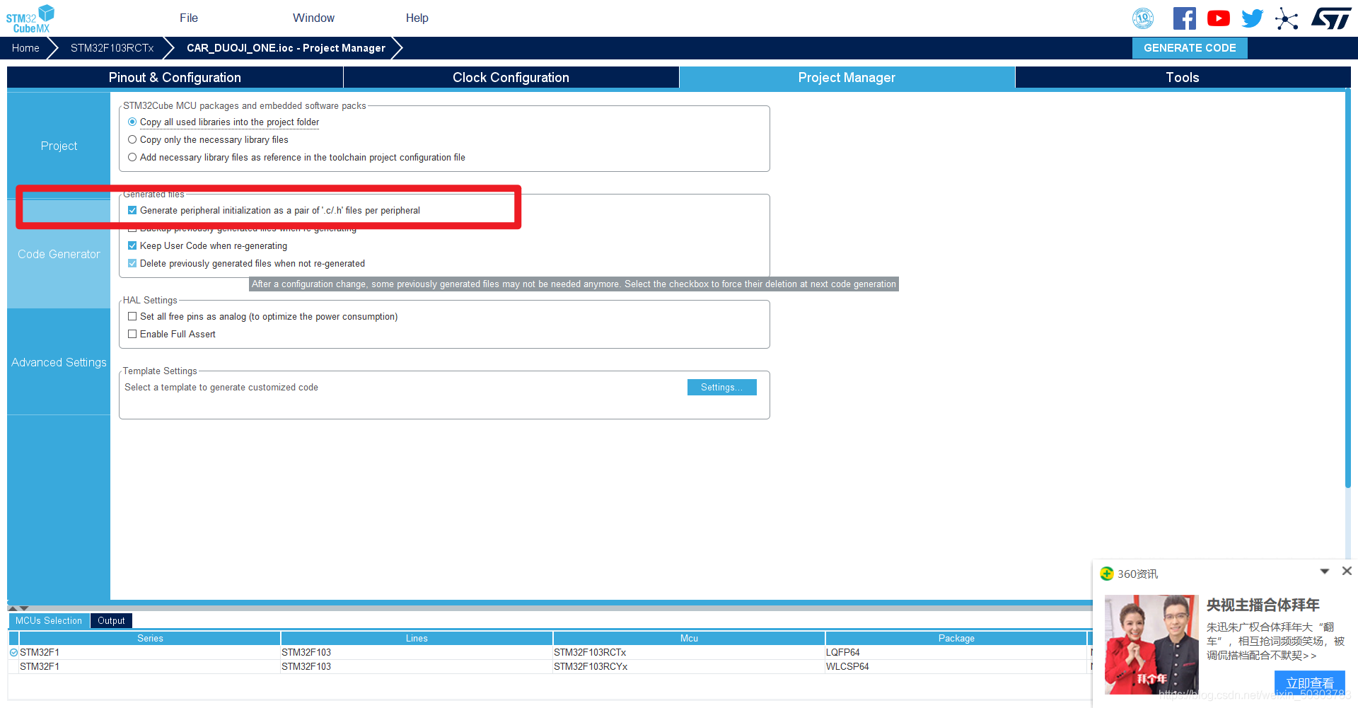
1. CUBE configuration
Here only TIM2 and its channel 2 are used for configuration (the basic content such as selecting the chip will not be repeated):
- Clock tree configuration
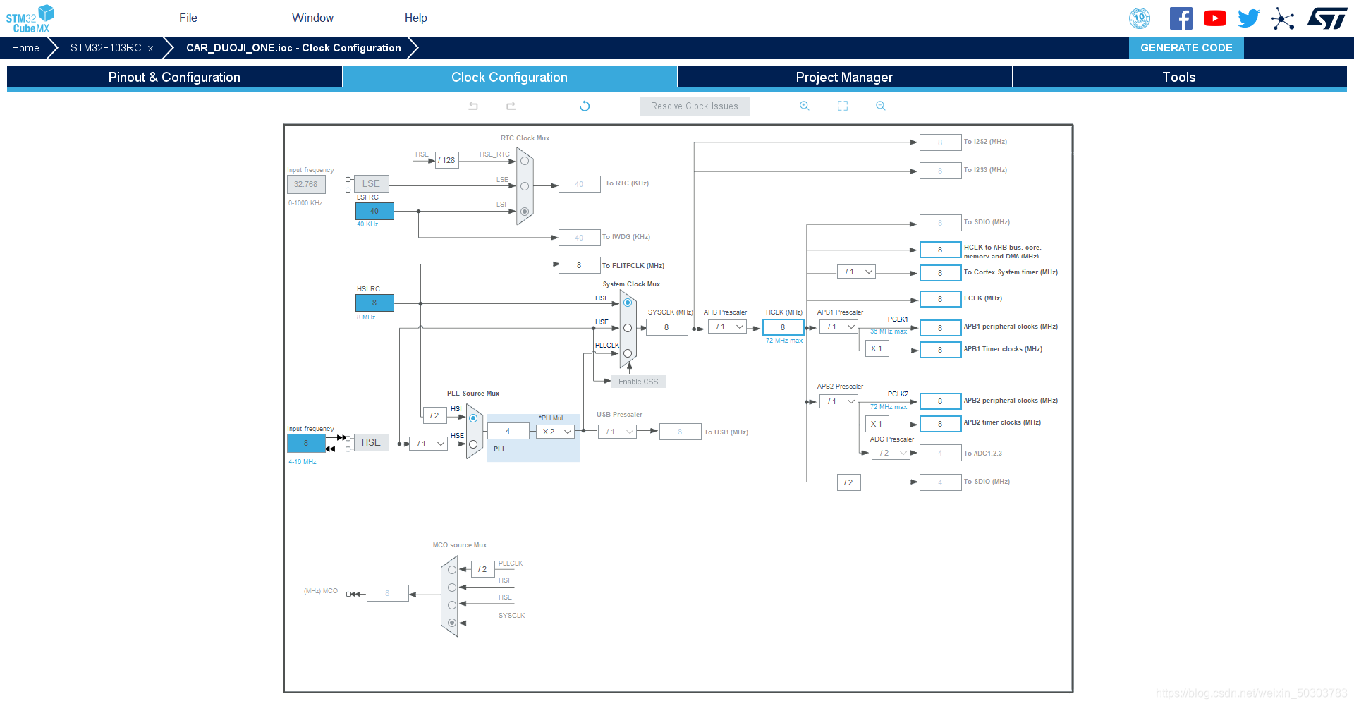
Here I use the default frequency division coefficient directly, without any changes, just change it according to my needs. - Select crystal oscillator clock
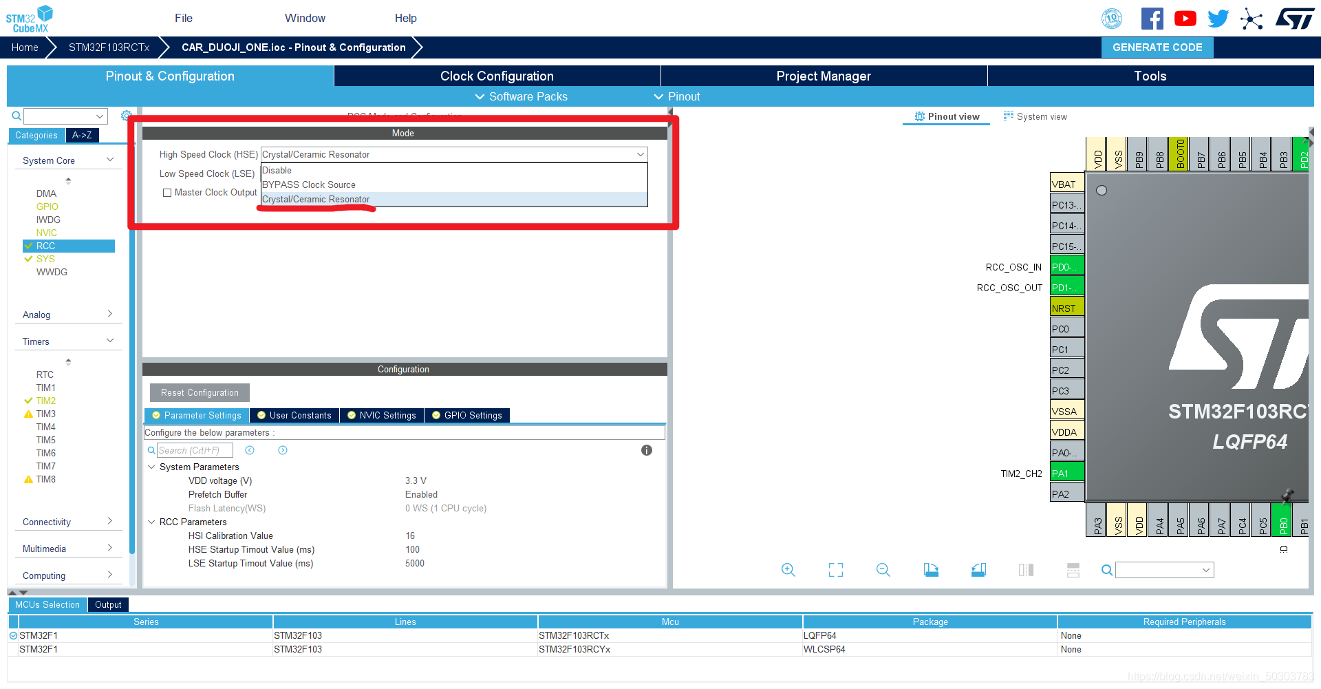
Click RCC to
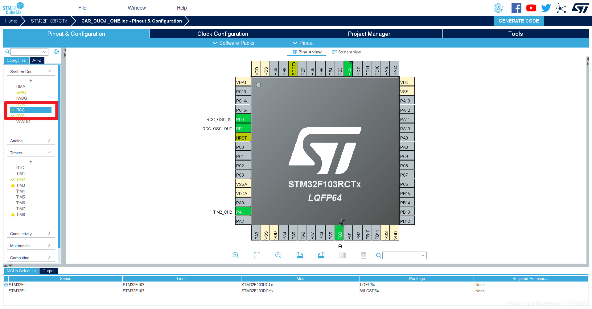
select quartz crystal oscillator
- Select the timer and its channel
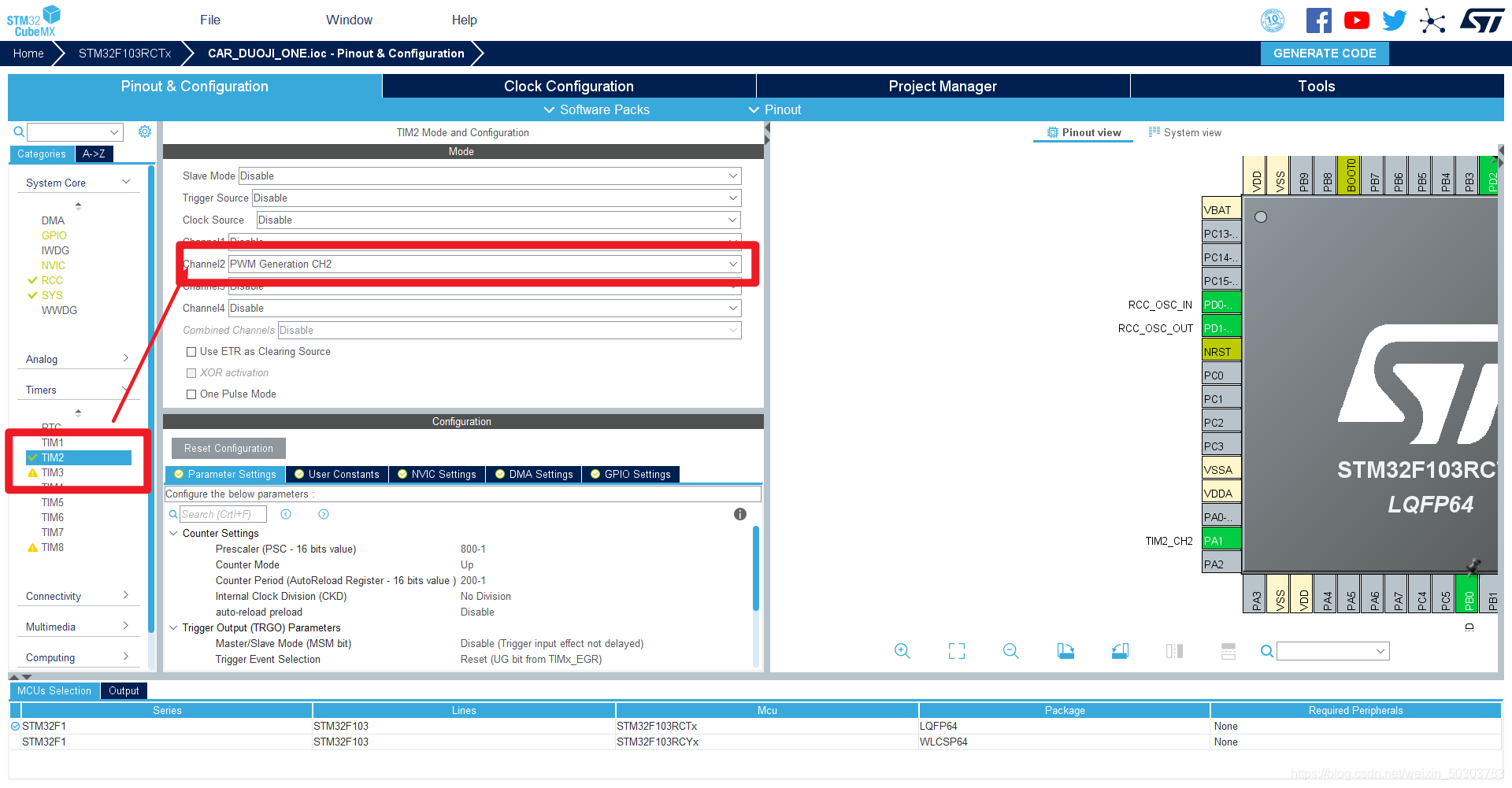
- Calculate parameters such as frequency division coefficient
- The frequency here is 8MHz, first divide it by 800: I
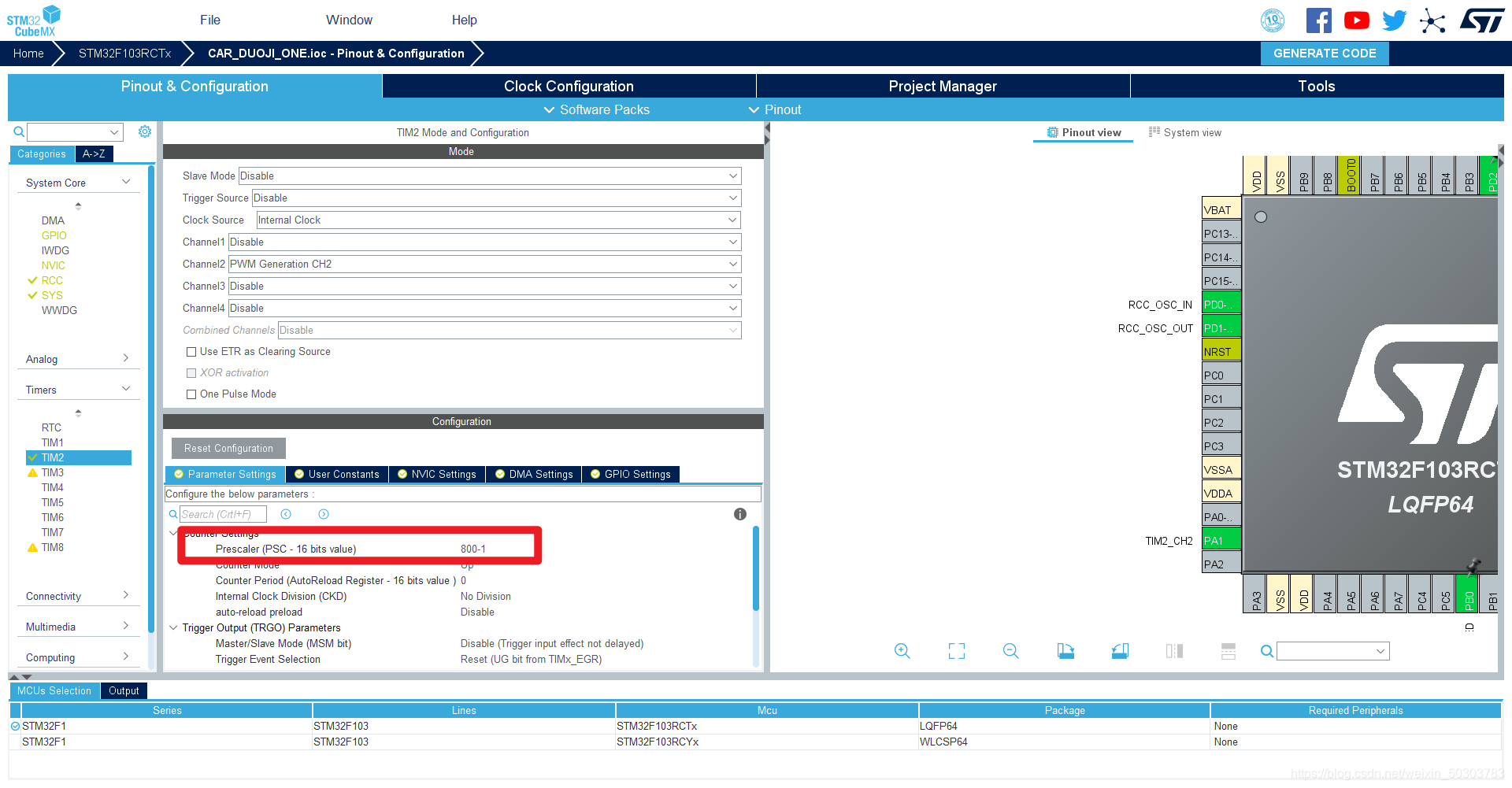
don't know why the eight-percent frequency is written as 800-1 here, it is recommended to look at the counter part of the counter to consolidate the basic knowledge. - The current counter plus one need to consume events is 1/(8MHz/800) = 0.1ms, if you want the cycle to be 20ms, you need to count 20/0.1 = 200 times, then the automatic reload value is 200
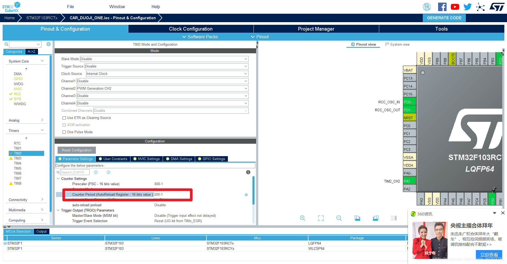
- Now the cycle is 20ms, we need to set the pulse width, counting 200 means 20ms, if you want the high level duration to be 1.5ms, you need to count 15 times, then our comparison value needs to be 15.
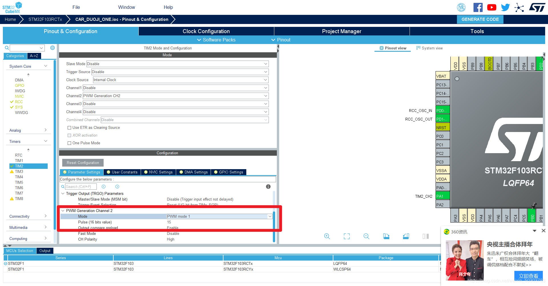
If we want to change it If it is the initial value, just change the value of CCR in the code.
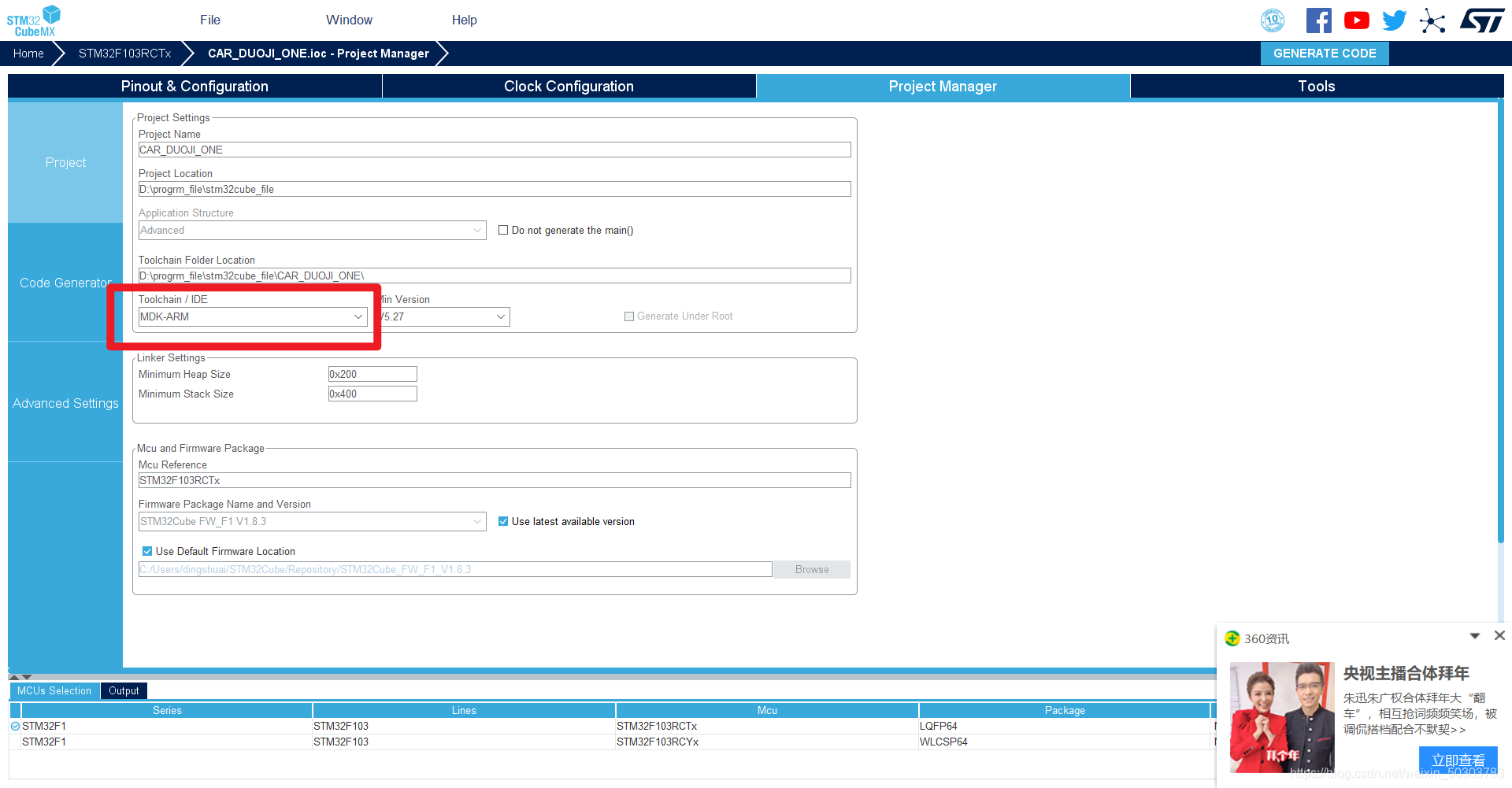
- Then export the code
2. Code addition
- Start the output of PWM
Add in the main function:
HAL_TIM_PWM_Start(&htim2, TIM_CHANNEL_2);
Means to start timer 2, channel 2 PWM output
2. Add in the while loop:
TIM2->CCR2=10;
HAL_Delay(2000);
TIM2->CCR2=20;
HAL_Delay(2000);
It means to change the comparison value to switch the output pulse width between 1000us and 2000us, so as to realize the deflection of the angle.
3. The overall main function is as follows:
int main(void)
{


  /* USER CODE BEGIN 1 */

  /* USER CODE END 1 */

  /* MCU Configuration--------------------------------------------------------*/

  /* Reset of all peripherals, Initializes the Flash interface and the Systick. */
  HAL_Init();

  /* USER CODE BEGIN Init */

  /* USER CODE END Init */

  /* Configure the system clock */
  SystemClock_Config();

  /* USER CODE BEGIN SysInit */

  /* USER CODE END SysInit */

  /* Initialize all configured peripherals */
  MX_GPIO_Init();
  MX_TIM2_Init();
  /* USER CODE BEGIN 2 */
	HAL_TIM_PWM_Start(&htim2, TIM_CHANNEL_2);
  /* USER CODE END 2 */

  /* Infinite loop */
  /* USER CODE BEGIN WHILE */
  while (1)
  {


    TIM2->CCR2=10;
		HAL_Delay(2000);
		TIM2->CCR2=21;
		HAL_Delay(2000);

		/* USER CODE END WHILE */

    /* USER CODE BEGIN 3 */
  }
  /* USER CODE END 3 */
}