1. Frame structure and physical resources (frame structure and physical resources)
1.1 General
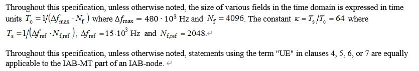
In this specification, unless otherwise specified, the size of each field in the time domain is expressed in time units:
![]() .......................................................①
.......................................................①
![]() ....................................................②
....................................................②
![]() .....................................................................③
.....................................................................③
From ②③ we can get Tc = 1/(4096*480*1000)s
In addition:
![]()
![]()
![]()
So Ts = 1/(2048*15*1000)s. Constant K = (4096*480)/(15*2048)=32*2=64
1.2 Numerologies
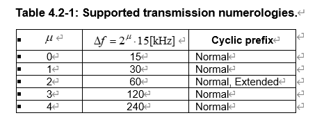
Multiple OFDM numerologies are supported as given by Table 4.2-1 where μ![]() and the cyclic prefix for a downlink or uplink bandwidth part are obtained from the higher-layer parameters subcarrierSpacing and cyclicPrefix, respectively ,
and the cyclic prefix for a downlink or uplink bandwidth part are obtained from the higher-layer parameters subcarrierSpacing and cyclicPrefix, respectively ,
Parameter μ from the layer parameter subcarrierSpacing control (subcarrier spacing), Cyclic prefix by a cyclic prefix parameter control cyclicPrefix.
Currently, the operator’s current network configuration has μ=1, that is, the subcarrier spacing is 30KHZ
1.3 Frame structure
1.3.1 Frame and subframe
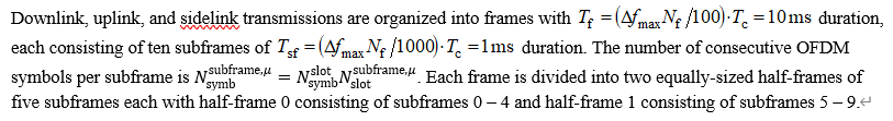
In uplink, downlink and side chain transmission, the frame transmission period is 10ms, which is divided into 10 subframes, and each subframe has a period of 1ms.
Each frame is divided into two congruent half-frames, Half-frame 0 contains 5 subframes 0-4, and Half-frame 1 contains 5 subframes 5-9.
The number of consecutive OFDM symbols on each subframe is![]()
The uplink frame transmission initiated from the UE is earlier than the downlink frame. When msgA is transmitted, Nta =0
The role of the time advance TA (Timing Advance) is to compensate for the transmission delay of the radio wave, and the fundamental purpose is to improve the efficiency of channel coding and decoding.

2.3.2 Slots(槽)

According to the operator of Mainland China, the value μ=1 is calculated:
The value of the slot number is {0, 1}, that is, there are 2 slots. If μ=4, the subcarrier spacing of 240KHZ is used, and the value range of the slot is {0, 15}, which means 16 slots. That is, 2 slots to the power of μ.
When μ=2, that is, when the cyclic prefix is normal/extrend, a Slot contains 12 OFDM symbols.
When μ≠2, a slot contains 14 symbol numbers.
Mainland China: μ=1, SCS=30KHZ; There are 2 slots in one frame, and 14 OFDM symbols in one slot.

2.4 Physical resources
2.4.1 Antenna ports
An antenna port is defined such that the channel over which a symbol on the antenna port is conveyed can be inferred from the channel over which another symbol on the same antenna port is conveyed.
The antenna port is defined so that the channel that transmits the symbol on the antenna port can be inferred from the channel that transmits another symbol on the antenna port
For DM-RS associated with a PDSCH, the channel over which a PDSCH symbol on one antenna port is conveyed can be inferred from the channel over which a DM-RS symbol on the same antenna port is conveyed only if the two symbols are within the same resource as the scheduled PDSCH, in the same slot, and in the same PRG as described in clause 5.1.2.3 of [6, TS 38.214].
DM-RS (demodulation reference signal, used at the receiving end (base station side or UE side) for channel estimation for physical channel demodulation) and PDSCH, PDSCH symbol channels transmitted on one antenna port can be inferred The DM-RS symbol is transmitted on the same antenna port. Only two symbols are on the same resource and scheduled PDSCH, in the same position, as described in PRG 5.1.2.3 (38.214 6, TS)
For DM-RS associated with a PDCCH, the channel over which a PDCCH symbol on one antenna port is conveyed can be inferred from the channel over which a DM-RS symbol on the same antenna port is conveyed only if the two symbols are within resources for which the UE may assume the same precoding being used as described in clause 7.3.2.2.
DM-RS and PDCCH, the channel of the PDCCH symbol transmitted on one antenna port can be inferred that the DM-RS symbol is transmitted on the same antenna port. There are only two symbols in the resource problem may assume the same precoding is used as 7.3. 2.2 Described terms.
For DM-RS associated with a PBCH, the channel over which a PBCH symbol on one antenna port is conveyed can be inferred from the channel over which a DM-RS symbol on the same antenna port is conveyed only if the two symbols are within a SS/PBCH block transmitted within the same slot, and with the same block index according to clause 7.4.3.1.
The channel of DM-RS and PBCH, PBCH symbol transmitted in one antenna port can be inferred that the DM-RS symbol is transmitted in the same antenna port. Only two symbols are transmitted in the same position in the SS/PBCH block, and the same block refers to data 7.4 .3.1 Clause.
Two antenna ports are said to be quasi co-located if the large-scale properties of the channel over which a symbol on one antenna port is conveyed can be inferred from the channel over which a symbol on the other antenna port is conveyed. The large-scale properties include one or more of delay spread, Doppler spread, Doppler shift, average gain, average delay, and spatial Rx parameters.
If the large-scale characteristics of the channel through which symbol transmission on one antenna port passes can be inferred from the channel through which symbol transmission on another antenna port passes, then the two antenna ports are said to be quasi-coordinated. Large-scale features include one or more delay spread, Doppler spread, Doppler shift, average gain, average delay, and spatial Rx parameters.
2.4.2 Resource grid

Looking mainly at the end of the first paragraph, Resource is composed of antenna port p. subcarrier spacing μ and transmission direction (uplink and downlink sidechain).
2.4.3 Resource elements
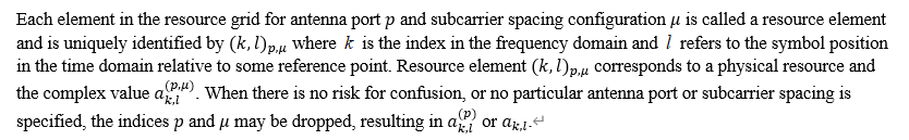
The elements configured with the unique antenna port p and subcarrier spacing μ in the resource grid are called resource elements.
2.4.4 Resource blocks (resource blocks)
①:A resource block is defined as NscRB=12 consecutive subcarriers in the frequency domain
12 consecutive subcarriers in the frequency domain are called a resource block. For domestic operators with μ=1, a resource block is listed in the frequency domain at 360KHZ.
②:Point A:
Point A serves as a common reference point for resource block grids and is obtained from:
- offsetToPointA for a PCell downlink where offsetToPointA represents the frequency offset between point A and the lowest subcarrier of the lowest resource block, which has the subcarrier spacing provided by the higher-layer parameter subCarrierSpacingCommon and overlaps with the SS/PBCH block used by the UE for initial cell selection, expressed in units of resource blocks assuming 15 kHz subcarrier spacing for FR1 and 60 kHz subcarrier spacing for FR2;
- absoluteFrequencyPointA for all other cases where absoluteFrequencyPointA represents the frequency-location of point A expressed as in ARFCN.
Point A is the common reference point of the resource block grid, which is determined by offsetToPointA and absoluteFrequencyPointA:
offsetToPointA represents the frequency offset between Point A and the lowest subcarrier in the lowest resource block, and absoluteFrequencyPointA represents the frequency position of Point A in ARFCN.
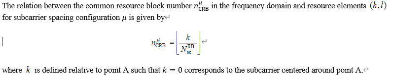
③ Common resource blocks (common resource blocks)
Common resource blocks are numbered from 0 and upwards in the frequency domain for subcarrier spacing configuration μ![]() . The center of subcarrier 0 of common resource block 0 for subcarrier spacing configuration μ
. The center of subcarrier 0 of common resource block 0 for subcarrier spacing configuration μ![]() coincides with 'point A'.
coincides with 'point A'.
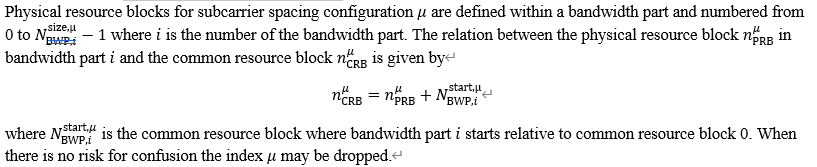
④ Physical resource blocks (physical resource blocks)
⑤ Virtual resource blocks (virtual resource blocks)
Virtual resource blocks are defined within a bandwidth part and numbered from 0 to ![]() where i
where i![]() is the number of the bandwidth part.
is the number of the bandwidth part.
⑥ Interlaced resource blocks (interlaced resource blocks)

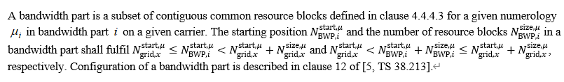
2.4.5 Bandwidth part (bandwidth part)
Bandwidth is a collection of consecutive common resource blocks.
A UE can be configured with up to four bandwidth parts in the downlink with a single downlink bandwidth part being active at a given time. The UE is not expected to receive PDSCH, PDCCH, or CSI-RS (except for RRM) outside an active bandwidth part.
The UE can be configured to have up to four bandwidth parts in the downlink, and only one downlink bandwidth part is active at a given time.
A UE can be configured with up to four bandwidth parts in the uplink with a single uplink bandwidth part being active at a given time. If a UE is configured with a supplementary uplink, the UE can in addition be configured with up to four bandwidth parts in the supplementary uplink with a single supplementary uplink bandwidth part being active at a given time. The UE shall not transmit PUSCH or PUCCH outside an active bandwidth part. For an active cell, the UE shall not transmit SRS outside an active bandwidth part.
The terminal can configure up to four bandwidth parts in the uplink, and one of the uplink bandwidth parts is active at a given time. If the terminal is configured with a supplementary uplink, the terminal can also configure up to 4 bandwidth parts in the supplementary uplink, and one of the supplementary uplink bandwidth parts is active at a given time. The UE shall not send push or compression outside the active bandwidth part. For an active unit, the terminal should not transmit SRS outside the active bandwidth part.
Unless otherwise noted, the description in this specification applies to each of the bandwidth parts. When there is no risk of confusion, the index μ![]() may be dropped from NBWP,istart,μ
may be dropped from NBWP,istart,μ![]() , NBWP,isize,μ
, NBWP,isize,μ![]() , Ngrid,xstart,μ
, Ngrid,xstart,μ![]() , and Ngrid,xsize,μ
, and Ngrid,xsize,μ![]() .
.
2.5 Carrier aggregation (carrier aggregation)

The high-level parameter ca-Slotoffset determines the Slot offset between PCell and Scell. The number of μ depends on the scs-specific carrierlist, which is defined as the maximum value of the lowest subcarrier interval.
3 Generic Function
3.1 Modulation mapper (modulation mapper)
The modulation mapper takes binary digits, 0 or 1, as input and produces complex-valued modulation symbols as output.
The modulation mapper takes binary digits 0 or 1 as input and produces complex-valued modulation symbols as output.
3.1.1 π / 2-BPSK

3.1.2 BPSK

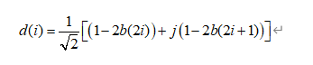
3.1.3 QPSK

3.1.4 16QAM

3.1.5 64QAM

3.1.6 256QAM

The rest of TS 38.211 requires strong mathematical ability, omitted.