1,Services and functions of the physical layer
1.1 General
The physical layer offers data transport services to higher layers (physical layer provides data transport services to higher layers).
The access to these services is through the use of transport channels via the MAC sub-layer (the access to these services is through the MAC layer transport channels).
A transport block is defined as the data delivered by MAC layer to the physical layer and vice versa (transport block is defined as the data delivered by the MAC layer to the physical layer and vice versa).
1.2 Overview of L1 functions
As mentioned in [2, TS 38.201], the physical layer is expected to perform the following functions to provide the data transport service:
-Error detection on the transport channel and indication to higher layers (error detection on the transport channel and indication to higher layers);
-FEC encoding/decoding of the transport channel (FEC encoding/decoding of the transport channel);
- Hybrid ARQ soft-combining( 混合ARQ soft-combining);
-Rate matching of the coded transport channel to physical channels (rate matching of the coded transport channel to physical channels);
-Mapping of the coded transport channel onto physical channels (mapping of the coded transport channel onto physical channels);
-Power weighting of physical channels (power weighting of physical channels);
-Modulation and demodulation of physical channels (modulation and demodulation of physical channels);
-Frequency and time synchronisation (time-frequency synchronization);
-Radio characteristics measurements and indication to higher layers (Radio characteristics measurements and indication to higher layers);
-Multiple Input Multiple Output (MIMO) antenna processing (Multiple Input Multiple Output (MIMO) antenna processing);
-RF processing (RF processing).
2. Model of physical layer of the UE (UE's physical layer model)
The 5G-NR physical-layer model captures those characteristics of the 5G-NR physical-layer that are relevant from the point-of-view of higher layers. More specifically, the physical-layer model captures:
-The structure of higher-layer data being passed down to or up from the physical layer (the structure of the higher layer data passed down or up from the physical layer);
-The means by which higher layers can configure the physical layer;
- The different indications (error indications, channel-quality indications, etc.) that are provided by the physical layer to higher layers (the different indications (error indications, channel-quality indications, etc.) provided by the physical layer to higher layers).
2.1 Uplink model
2.1.1 Uplink shared channel
The physical-layer model for Uplink Shared Channel transmission is described based on the corresponding PUSCH physical-layer-processing chain, see Figure 5.1.1-1. Processing steps that are relevant for the physical-layer model, eg in the sense that they are configurable by higher layers, are highlighted in blue.
-Higher-layer data passed to/from the physical layer (From and to physical layer and high-level data transmission)
-CRC and transport-block-error indication (Cyclic Redundancy Check) Additional check and fast transmission error indication)
-FEC and rate matching (FEC and rate matching)
-Data modulation (data modulation)
-Mapping to physical resource (and physical resource mapping)
-Multi-antenna processing (multi-antenna processing)
-Support of L1 control and Hybrid-ARQ-related signalling (supports L1 control and hybrid-arq related signalling)

2.1.2 Random access channel:
The characteristic of the physical layer model of RACH transmission is a PRACH preamble format, which consists of a cyclic prefix, a preamble and a guard time that does not transmit anything.
2.2 Downlink Model
2.2.1 Downlink shared channel
The physical-layer model for Downlink Shared Channel transmission is described based on the corresponding PDSCH physical-layer-processing chain, see Figure 5.2.1-1. Processing steps that are relevant for the physical-layer model, eg in the sense that they are configurable by higher layers, are highlighted in blue.
-Higher-layer data passed to/from the physical layer (From and to physical layer and high-level data transmission)
-CRC and transport-block-error indication (Cyclic Redundancy Check) Additional check and fast transmission error indication)
-FEC and rate matching (FEC and rate matching)
-Data modulation (data modulation)
-Mapping to physical resource (and physical resource mapping)
-Multi-antenna processing (multi-antenna processing)
-Support of L1 control and Hybrid-ARQ-related signalling (supports L1 control and hybrid-arq related signalling)
2.2.2 Broadcast channel
The physical-layer model for BCH transmission is characterized by a fixed pre-defined transport format. There is one transport block for the BCH every 80ms. The BCH physical-layer model is described based on the corresponding PBCH physical-layer-processing chain, see Figure 5.2.2-1:-Higher
-layer data passed to/from the physical layer (From and to physical layer and high-level data transmission)
-CRC and transport-block-error indication (Cyclic Redundancy Check) Transmission fast error indication)
-FEC and rate matching (FEC and rate matching)
-Data modulation (data modulation)
-Mapping to physical resource (and physical resource mapping)
-Multi-antenna processing (multi-antenna processing)
2.2.3 Paging channel
The physical-layer model for PCH transmission is described based on the corresponding physical-layer-processing chain, see Figure 5.2.3-1. The PCH is carried on PDSCH. Processing steps that are relevant for the physical-layer model, eg in the sense that they are configurable by higher layers, are highlighted in blue.
-Higher-layer data passed to/from the physical layer (From and to physical layer and high-level data transmission)
-CRC and transport-block-error indication (Cyclic Redundancy Check cyclic redundancy check and fast transmission error indication)
-FEC and rate matching (FEC and rate matching)
-Data modulation (data modulation)
-Mapping to physical resource (and physical resource mapping)
-Multi-antenna processing (multi-antenna processing ) deal with)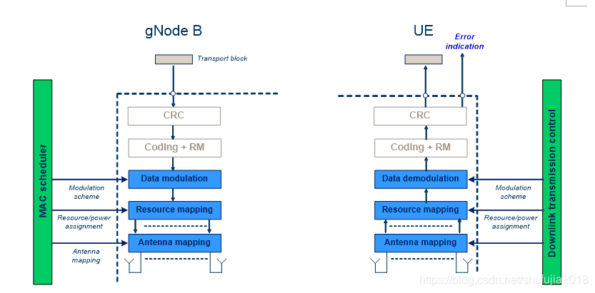
2.3 Shindo Shindo:
2.3.1 Sidelink shared channel:
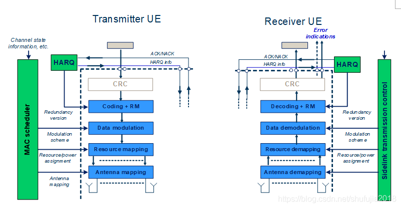
The physical-layer model for Sidelink Shared Channel transmission is described based on the corresponding SL-SCH physical-layer-processing chain, see Figure 5.3.1-1. Processing steps that are relevant for the physical-layer model, e.g. in the sense that they are configurable by higher layers, are highlighted in blue.
-Higher-layer data passed to/from the physical layer (From and to physical layer and high-level data transmission)
-CRC and transport-block-error indication (Cyclic Redundancy Check cyclic redundancy check and transmission fast error indication)
-FEC and rate matching (FEC and rate matching)
-Data modulation (data modulation)
-Mapping to physical resource (and physical resource mapping)
-Multi-antenna processing (multi-antenna processing)
-Support of L1 control and Hybrid-ARQ-related signalling ( Support L1 control and hybrid-arq related signaling)
2.3.2 Broadcast channel
The physical-layer model for Sidelink Broadcast Channel transmission is characterized by a fixed pre-defined transport format. There is one transport block for every slot in which the UE transmits SL-BCH, if the UE is configured to transmit on SL-BCH. The SL-BCH physical-layer model is described based on the corresponding SL-BCH physical-layer-processing chain, see Figure 5.3.2-1:
-Higher-layer data passed to/from the physical layer (From and to physical layer and high-level data transmission)
-CRC and transport-block-error indication (Cyclic Redundancy Check cyclic redundancy check and transmission fast error indication)
-FEC and rate matching (FEC and rate matching)
-Data modulation (data modulation)
-Mapping to physical resource (and physical resource mapping)
-Multi-antenna processing (multi-antenna processing)

4,The physical-layer model for RACH transmission is characterized by a PRACH preamble format Simultaneous transmission and reception of physical channels and physical signals
(The characteristic of the physical layer model of RACH transmission is the use of PRACH preamble format, which simultaneously transmits and receives physical channels and physical signals)
This clause describes the requirements from the UE to send and receive multiple physical channels and physical signals simultaneously (同时)depending on the capabilities and service requirements. The following notation(注释) is used between both the uplink and downlink clauses below.
- p is the number of uplink carriers configured for the UE on which physical channels can be transmitted
- p' is the number of uplink carriers configured for the UE on which SRS can be transmitted
- q is the number of downlink carriers configured for the UE
- j is the number of cell groups configured for the UE.
- k is the number of PUCCH groups configured for the UE.
4.1 Uplink
The tables 6.1-1 and 6.1-2 describe the possible combinations of physical channels and SRS that can be sent in simultaneously in the uplink by one UE. Table 6.1-1 introduces notation for a "Transmission Type" which represents a physical channel or sounding reference signal, and any associated transport channel. Table 6.1-2 describes the combinations of these "Transmission Types" which are supported by the UE depending on capabilities [8, TS 38.306], and enumerates how many of each can be transmitted simultaneously.
Uplink "Transmission Types"
| "Transmission Type" |
Physical Channel or SRS |
Associated |
Comment |
| A |
DUST |
RACH |
Note 1, Note 3 |
| B |
PUCCH |
N/A |
|
| C |
PUSCH |
UL-SCH |
Note 2, Note 3 |
| D |
SRS |
N/A |
|
| Note 1: RACH corresponds to contention based. Note 2: UCI on PUSCH without UL-SCH is possible. Note 3: For SCell, MsgA PRACH and MsgA PUSCH is not supported. |
|||
Uplink "Transmission Type" combinations
| Supported Combinations |
Comment |
| j x A |
Note 1 |
| k x B |
Note 2 |
| p x C |
Note 3, Note 4 |
| p' x D |
Note 3, Note 5 |
| j× |
Note 6 |
| j× |
Note 6 |
| j× |
Note 6 |
| k× |
Note 8 |
| k× |
Note 7 |
| p× |
Note 7 |
| Note 1: The number of cell groups j in the supported combination is subject to UE capability. Note 2: The number of PUCCH groups k in the supported combination is subject to UE capability. Note 3: The number of carriers p, and p' in the supported combinations are subject to UE capability. Note 4: In the case there is one SUL carrier, then p-1 would be supported. Note 5: UE may be configured with p' but may also have capability to simultaneously sound less than this number. Note 6: Simultaneous PRACH with PUCCH (or PUSCH or SRS) is supported only in the case of inter-band CA, with j≤j Note 7: Simultaneous SRS with PUCCH (or PUSCH) is supported only in the case of inter-band CA, with k≤k Note 8: Simultaneous PUCCH and PUSCH(s) is supported only in the case that multiple PUCCH groups are configured and the respective PUCCH and PUSCH(s) are transmitted in the different PUCCH groups, with k<k |
|
4.2 Downlink
The tables 6.2-1, 6.2-2 describe the possible combinations of physical channels that can be received simultaneously in the downlink by one UE. Table 6.2-1 introduces notation for a "Reception Type" which represents a physical channel and any associated transport channel. Table 6.2-2 describes the combinations of these "Reception Types" which are supported by the UE depending on capabilities [8, TS 38.306], and enumerates how many of each can be received simultaneously. The UE shall be able to receive all TBs according to the indication on PDCCH. Any subset of the combinations specified in table 6.2-2 is also supported.
Downlink "Reception Types"
| "Reception Type" |
Physical Channel(s) |
Monitored |
Associated |
Comment |
| A |
PBCH |
N/A |
BCH |
|
| B |
PDCCH+PDSCH |
SI-RNTI |
DL-SCH |
Note 1 |
| C0 |
PDCCH |
P-RNTI |
N/A |
Note 1, Note 2 |
| C1 |
PDCCH+PDSCH |
P-RNTI |
PCH |
Note 1 |
| D0 |
PDCCH+PDSCH |
RA-RNTI or Temporary C-RNTI or MsgB-RNTI |
DL-SCH |
Note 3 |
| D1 |
PDCCH+PDSCH |
C-RNTI, CS-RNTI, MCS-C-RNTI |
DL-SCH |
|
| D2 |
PDCCH |
C-RNTI, CS-RNTI, MCS-C-RNTI |
DL-SCH |
|
| E |
PDCCH |
C-RNTI |
N/A |
Note 4 |
| F0 |
PDCCH |
Temporary C-RNTI |
UL-SCH |
Note 3 |
| F1 |
PDCCH |
C-RNTI, CS-RNTI, MCS-C-RNTI |
UL-SCH |
|
| G |
PDCCH |
SFI-RNTI |
N/A |
|
| H |
PDCCH |
INT-RNTI |
N/A |
|
| J0 |
PDCCH |
TPC-PUSCH-RNTI |
N/A |
|
| J1 |
PDCCH |
TPC-PUCCH-RNTI |
N/A |
|
| J2 |
PDCCH |
TPC-SRS-RNTI |
N/A |
|
| K |
PDCCH |
SP-CSI-RNTI |
N/A |
|
| L0 |
PDCCH |
SL-RNTI |
SL-SCH |
|
| L1 |
PDCCH |
SL-CS-RNTI |
SL-SCH |
|
| M |
PDCCH |
SL Semi-Persistent Scheduling V-RNTI |
SL-SCH |
Note 5 |
| N |
PDCCH |
PS-RNTI |
N/A |
|
| O |
PDCCH |
AI-RNTI |
N/A |
|
| Note 1: These are received from PCell only. Note 2: In some cases UE is only required to monitor the short message within the DCI for P-RNTI. Note 3: These are received from PCell or PSCell. Note 4: This corresponds to PDCCH-ordered PRACH. Note 5: This corresponds to PDCCH scheduling LTE PC5. |
||||
Downlink "Reception Type" combinations
| Supported Combinations |
Comment |
||
| PCell |
PSCell |
SCell |
|
| 1. RRC_IDLE |
|||
| A + (B and/or C1 and/or D0) + F0 |
|
|
Note 1 |
| 2. RRC_INACTIVE |
|||
| A + (B and/or C1 and/or D0) + F0 |
|
|
Note 1 |
| 3. RRC_CONNECTED |
|||
| (A + C0 + (B and/or (D0 or (m1*D1+m2*D2))) + E + F0 + n*F1 + G + H + J0 + J1 + J2 + K + O + L0 + L1 + M + N) |
(A + (D0 or (m1*D1+m2*D2)) + E + F0 + n*F1 + G + H + J0 + J1 + J2 + K + O + N) |
m1*D1 + m2*D2 + E + n*F1 + G + H + J0 + J1 + J2 + K + O + L0 + L1 + M |
Note 2, Note 3, Note 4, Note 5, Note 6, Note 7, Note 8 |
| Note 1: UE is not required to decode more than two PDSCH simultaneously, and decoding prioritization when more than two are received is up to UE implementation. Note 2: For PCell, UE is not required to decode SI-RNTI PDSCH simultaneously with C-RNTI PDSCH, unless in FR1. Note 3: Supported combinations are subject to UE capabilities for dual connectivity, carrier aggregation, receiving of group TPC commands, pre-emption indication and dynamic SFI monitoring. Note 4: The values of m2 ≥ 0 and n≥ 0 in the supported combinations are subject to the UE capability. Note 5: Support of monitoring PDCCH with SL-RNTI, SL-CS-RNTI, SL Semi-Persistent Scheduling V-RNTI are subject to UE capability. Note 6: The values of m1 ≥ 1 in the supported combinations are subject to the UE capability. Note 7: In Active time, a UE is not expected to monitor the DCI format for the PDCCH scrambled by PS-RNTI. Note 8: The PDCCH scrambled by PS-RNTI can only be configured on the PCell and PSCell. |
|||
4.2 Slidelink
The tables 6.3-1 and 6.3-2 describe the possible combinations of physical channels that can be sent simultaneously in the sidelink by a UE. Table 6.3-1 introduces notation for a sidelink "Transmission Type" which represents a physical channel, and any associated transport channel. Table 6.3-2 describes the combinations of these "Transmission Types" which are supported by the UE depending on capabilities [8, TS 38.306], and enumerates how many of each can be transmitted simultaneously.
Sidelink "Transmission Types"
| "Transmission Type" |
Physical Channel |
Associated |
Comment |
| A |
PSBCH |
SL-BCH |
|
| B |
PSSCH |
SL-SCH |
|
| C |
PSCCH |
SL-SCH |
|
| D |
PSFCH |
N/A |
|
|
|
|||
Sidelink "Transmission Type" combinations
| Supported Combinations |
Comment |
| A |
|
| B |
|
| C |
|
| N× |
|
| B+C |
|
| Note: Depending on the UE capability, the UE may be able to perform simultaneous Uplink and Sidelink transmissions. If the simultaneous transmission of Sidelink and Uplink is beyond the UE capability, the one not prioritized can be dropped according to [TS 38.321. |
|
The tables 6.3-3 and 6.3-4 describe the possible combinations of physical channels that can be received simultaneously in the sidelink by a UE. Table 6.3-3 introduces notation for a sidelink "Reception Type" which represents a physical channel, and any associated transport channel. Table 6.3-4 describes the combinations of these "Transmission Types" which are supported by the UE depending on capabilities [8, TS 38.306], and enumerates how many of each can be received simultaneously.
Sidelink "Reception Types"
| "Transmission Type" |
Physical Channel |
Associated |
Comment |
| A |
PSBCH |
SL-BCH |
|
| B |
PSSCH |
SL-SCH |
|
| C |
PSCCH |
SL-SCH |
|
| D |
PSFCH |
N/A |
|
|
|
|||
Sidelink "Reception Type" combinations
| Supported Combinations |
Comment |
| A |
|
| B |
Note 1 |
| C |
Note 1 |
| M× |
|
| B+C |
Note 1 |
| Note 1: Corresponds to simultaneous reception within one sub-channel |
|
5 Measurements provided by the physical layer
5.1 UE measurements
The list and detailed definition of UE measurements is provided in [7, TS 38.215].