51 single chip microcomputer drives LCD1602 liquid crystal display system PROTEUS simulation and source code design
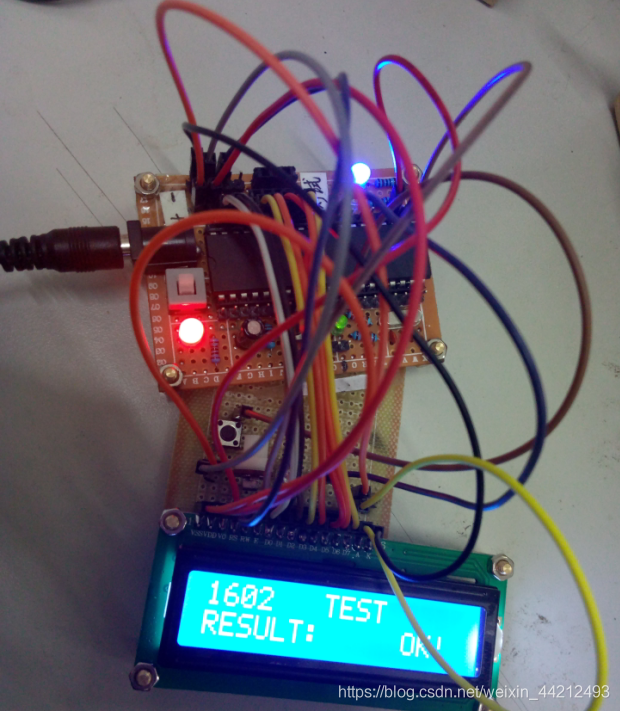
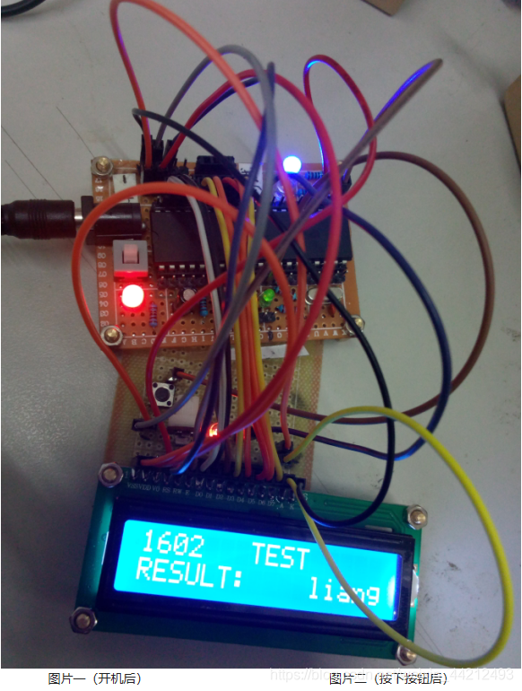
Without further ado, let's go to the physical map
LCD1602 + 51 single-chip microcomputer minimum system application simulation and production
, and then formally enter the production link:
Step 1: Simulation
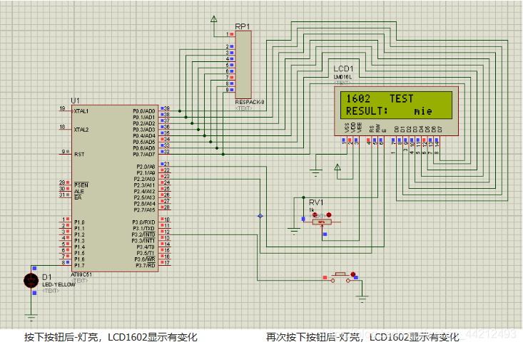
Draw a good schematic diagram. In the simulation, the minimum system of the single-chip microcomputer only needs to put one single-chip microcomputer, but the actual circuit needs to add the power supply module and the reset module. As shown below:
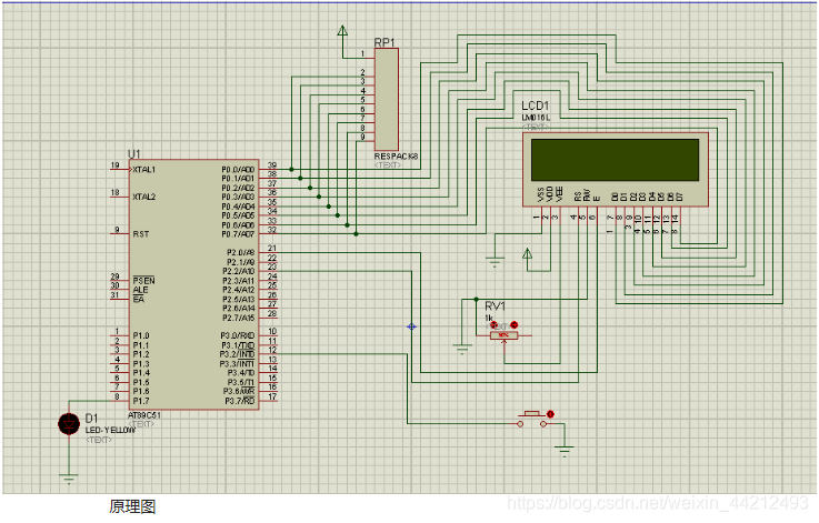
Please find the schematic file in the attachment.
After the schematic is drawn, write the code and generate the hex file. The reference code is as follows:
/ * Function /
/ Use external interrupt INTO to change LED status and display its status with 1602 /
#include <reg51.h>
#include <intrins.h>
#define uint unsigned int
#define uchar unsigned char
uchar code table [] = "HELLO 1602";
uchar code table0 [] = "1602 TEST";
uchar code table1 [] = "RESULT:"; // The space is written to the LCD, that is, the space is also the content
uchar code table2 [] = “OK! ”;
Uchar code table3 [] =“ liang ”;
uchar code table4 [] =“ mie ”;
uchar num;
sbit led = P1 ^ 7;
sbit lcden = P2 ^ 0; // LCD enable terminal
sbit lcdrs = P2 ^ 2; // The LCD data command selection terminal chooses to write data or write command
void delay (uint z) // Delay function
{
uint i, j;
for (i = z; i> 0; i--)
for (j = 110 ; j> 0; j–);
}
void write_com (uchar com) // Write
{
lcdrs = 0; // LCD select input command
P0 = com; // Enter command to P0 port 39-32 port
delay (5); // Delay
lcden = 1; / / Turn on LCD to enable
delay (5); // A high pulse
lcden = 0; // Turn off LCD to enable
}
void write_data (uchar date)
{
lcdrs = 1; // Set to input data
P0 = date; // Will Data is assigned to P0 port
delay (5); // Delay
lcden = 1; // Set high
delay (5); // High pulse
lcden = 0; // Set low to complete high pulse
}
void init () // LED Initialize
{
lcden = 0;
write_com (0x38); // Set 16x2 to display 5x7 dot matrix, 8-bit data interface
write_com (0x0c); // Set to start display without cursor (command 4)
write_com (0x06); // Write a Add 1 to the address pointer after the character (instruction 3)
write_com (0x01); // Display clear data pointer to zero (instruction 1)
}
void display (unsigned char * p) // Write data by pointer address
{
while (* p! = '\ 0')
{
write_data (* p); // Write data
p ++;
delay (1);
}
}
void main ()
{
TCON = 0x01; // Set the interrupt to INTO
IE = 0x81;
led = 0;
init ();
write_com (0x80); // Set the first word of the first line of the data pointer,
display (table) ; // Write the data by calling the function
delay (800);
write_com (0x80); // Write the first word of the first line of the data pointer,
display (table0); // Write the data by calling the function
write_com ( 0x80 + 0x40); // Define the position of the pointer and place the first word of the second line of the data pointer
for (num = 0; num <7; num ++)
{
write_data (table1 [num]);
delay (5);
}
write_com ( 0x80 + 0x4c); // write data individually according to the address of 1602
write_data (table2 [0]);
write_com (0x80 + 0x4d); // write data individually according to the address of 1602
write_data (table2 [1]);
write_com ( 0x80 + 0x4e); // write data individually according to the address of 1602
write_data (table2 [2]);
while (1);
}
void key_can () interrupt 0
{
delay (20); // Eliminate key jitter
if (P3 ^ 30)
{
if(P3^30)
{
ice =! Ice;
}
if(led1)
{
write_com(0x80+0x4b);
display(table3);
}
else if(led0)
{
write_com (0x80 + 0x4b); // Single write data according to the address of 1602
display (table4);
write_com (0x80 + 0x4f);
write_data (table1 [8]); // Single write data according to the address of 1602
write_com (0x80 + 0x4e);
write_data (table1 [8]);
}
}
}
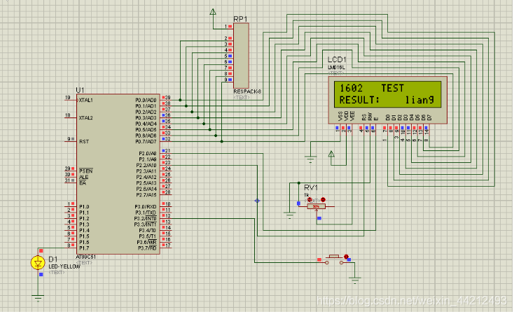
The schematic diagram and code are available, and the preparation for the simulation is finished. Now the simulation is officially entered.
Load the code into the microcontroller, the simulation results are as follows:
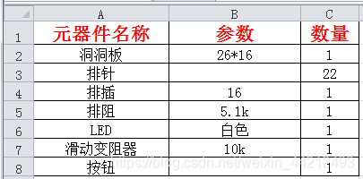
Component list
The original layout and effect diagram are as follows:
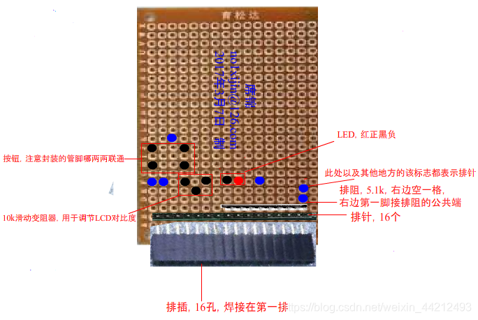
Finally, all are welded according to the requirements, and the electric burning program can be tested.
It should be written in sufficient detail. If there is something that you do n’t understand, or if you need to design documents, please leave me a message or private letter me!
