this design
Air quality detection and alarm simulation design based on STM32 (simulation + program + explanation)
Air quality detection and alarm simulation design based on STM32 (simulation + program + explanation)
Simulation diagram proteus 8.9
Program compiler: keil 5
Programming language: C language
Design number: C0084
1. Main functions
Function Description:
1. Use STM32the microcontroller and MQ-135control core to design the air quality detection and alarm design;
2. LCD1602The air quality is displayed on the LCD screen and serial port host computer, MV represents the detection value, and ALM represents the alarm value;
3. The air quality ALM alarm value can be set by pressing the button.
4. When the monitored air quality is greater than the alarm value, 蜂鸣器the alarm circuit is turned on and the buzzer alarms.
5. By default, the buzzer alarm will sound when the air quality is higher than 200ppm.
Main hardware equipment:STM32F103单片机
The following is a display of this design information:
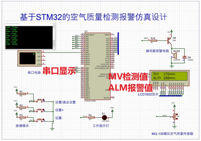
2. Simulation
Overall design plan
This experiment uses the ADC, GPIO, timer and other resources of the STM32 microcontroller to organically combine the software and hardware, so that the system can correctly identify the AD value input to the simulated air quality sensor, and the LCD1602 can display it correctly, and the buzzer can be displayed according to the Air quality alarm values work. It should be noted that proteus does not have air concentration sensors such as MQ-135. This design uses a sliding rheostat to simulate changes in air quality and cannot be directly used in physical design. If necessary, it must be debugged according to the physical object.
This test looks like this:
Simulation running status:
After starting the simulation, LCD1602 displays the detected air quality in real time, and the measured value can be changed through the sliding rheostat. The alarm value concentration can be set by pressing the button, press the setting button to enter the setting mode, increase the alarm value through setting +, and decrease the alarm value through setting -. The buzzer alarm circuit starts when the air quality is higher than the alarm value, and there is a beeping alarm sound, and it does not start when the air quality is lower than the alarm value.
This design uses an electromagnetic buzzer. The electromagnetic buzzer consists of an oscillator, electromagnetic coil, magnet, vibrating diaphragm and shell. After the power is turned on, the audio signal current generated by the oscillator passes through the electromagnetic coil, causing the electromagnetic coil to generate a magnetic field. The vibrating diaphragm periodically vibrates and produces sound under the interaction of the electromagnetic coil and the magnet. Therefore, a certain current is required to drive it. The current output by the I/O pin of the microcontroller is small. The TTL level output by the microcontroller basically cannot drive the buzzer, so a current amplification circuit needs to be added. The positive electrode of the buzzer is connected to the VCC (+5V) power supply, the negative electrode of the buzzer is connected to the collector C of the triode, and the base B of the triode is controlled by the BEEP pin of the microcontroller after passing through the current limiting resistor. When the BEEP output is low When BEEP outputs a high level, the triode QS is turned off, no current flows through the coil, and the buzzer does not sound; when BEEP outputs a high level, the triode is turned on, so that the current of the buzzer forms a loop and makes a sound.
The picture below shows that the air quality is 176, which is lower than the alarm value of 200, and the buzzer circuit does not work.
The picture below detects that the air quality index is 204, which is greater than or equal to the alarm value. The transistor is turned on and the buzzer alarms.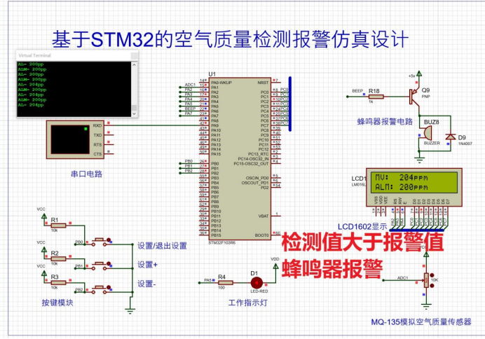
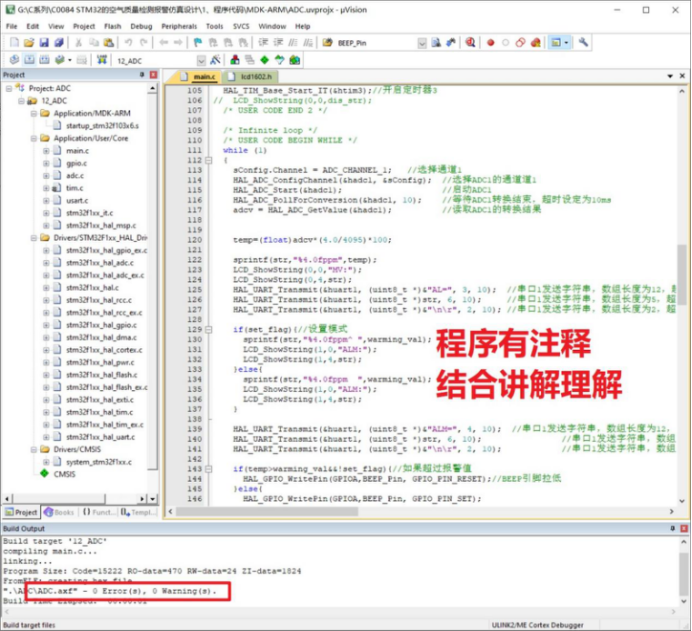
int main(void)
{


  /* USER CODE BEGIN 1 */
	ADC_ChannelConfTypeDef sConfig = {

    0};  //建立sConfig结构体
	char str[20];  //字符串的存放数组
	uint32_t adcv; //存放ADC转换结果
	float temp;
	set_flag = 0;


  /* USER CODE END 1 */

  /* MCU Configuration--------------------------------------------------------*/

  /* Reset of all peripherals, Initializes the Flash interface and the Systick. */
  HAL_Init();

  /* USER CODE BEGIN Init */
	sConfig.Rank = ADC_REGULAR_RANK_1;
	sConfig.SamplingTime = ADC_SAMPLETIME_1CYCLE_5;   //采样周期为1.5个周期
  /* USER CODE END Init */

  /* Configure the system clock */
  SystemClock_Config();

  /* USER CODE BEGIN SysInit */

  /* USER CODE END SysInit */

  /* Initialize all configured peripherals */
  MX_GPIO_Init();
  MX_ADC1_Init();
  MX_USART1_UART_Init();
  MX_TIM3_Init();
  /* USER CODE BEGIN 2 */
	LCD_Init();  //初始化LCD1602
	HAL_TIM_Base_Start_IT(&htim3);//开启定时器3
//	LCD_ShowString(0,0,dis_str);
  /* USER CODE END 2 */

  /* Infinite loop */
  /* USER CODE BEGIN WHILE */
  while (1)
  {


		sConfig.Channel = ADC_CHANNEL_1;   //选择通道1
		HAL_ADC_ConfigChannel(&hadc1, &sConfig);  //选择ADC1的通道道1
		HAL_ADC_Start(&hadc1);										//启动ADC1
		HAL_ADC_PollForConversion(&hadc1, 10);		//等待ADC1转换结束,超时设定为10ms
		adcv = HAL_ADC_GetValue(&hadc1);					//读取ADC1的转换结果


		temp=(float)adcv*(4.0/4095)*100;

		sprintf(str,"%4.0fppm",temp);
		LCD_ShowString(0,0,"MV:");
		LCD_ShowString(0,4,str);
	  HAL_UART_Transmit(&huart1, (uint8_t *)&"AL=", 3, 10);  //串口1发送字符串,数组长度为12,超时10ms
		HAL_UART_Transmit(&huart1, (uint8_t *)str, 6, 10);		 //串口1发送字符串,数组长度为5,超时10ms
		HAL_UART_Transmit(&huart1, (uint8_t *)&"\n\r", 2, 10); //串口1发送字符串,数组长度为2,超时10ms

		if(set_flag){

    //设置模式
			sprintf(str,"%4.0fppm^ ",warming_val);
			LCD_ShowString(1,0,"ALM:");
			LCD_ShowString(1,4,str);
		}else{


			sprintf(str,"%4.0fppm  ",warming_val);
			LCD_ShowString(1,0,"ALM:");
			LCD_ShowString(1,4,str);
		}

	  HAL_UART_Transmit(&huart1, (uint8_t *)&"ALM=", 4, 10);  //串口1发送字符串,数组长度为12,超时10ms
		HAL_UART_Transmit(&huart1, (uint8_t *)str, 6, 10);								//串口1发送字符串,数组长度为5,超时10ms
		HAL_UART_Transmit(&huart1, (uint8_t *)&"\n\r", 2, 10);						//串口1发送字符串,数组长度为2,超时10ms

		if(temp>warming_val&&!set_flag){

    //如果超过报警值
			HAL_GPIO_WritePin(GPIOA,BEEP_Pin, GPIO_PIN_RESET);//BEEP引脚拉低
		}else{


			HAL_GPIO_WritePin(GPIOA,BEEP_Pin, GPIO_PIN_SET);
		}

		HAL_ADC_Stop(&hadc1);											//停止ADC1
		HAL_Delay(300);
    /* USER CODE END WHILE */

    /* USER CODE BEGIN 3 */
  }
  /* USER CODE END 3 */
}
3. Procedure
The program is opened with the keil5 mdk version. If there are problems opening it, check the keil version. The program is written in the HAL library version, and there are comments that can be understood in conjunction with the explanation video.
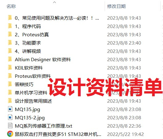
4. Information list & download link
0. Common usage problems and solutions – a must-read! ! ! !
1. Program code
2. Proteus simulation
3. Functional requirements
4. Explanation video
Altium Designer Software Information
filename.bat
KEIL software information
MQ135-2.jpg
MQ135.jpg
MQ series sensor working principle.txt
Proteus software information
Microcontroller learning materials
Defense skills
Common descriptions for design reports
Double-click the mouse to open and find more 51 STM32 Microcontroller Course Graduation Project.url