In the first chapter, the IP overview mentioned that the Internet is a network of networks . Only when the network and the network are connected to each other, the data on the network can be shared and the hosts can be connected. We know that the Internet is composed of many networks connected together, so how can data packets sent by users reach their destinations accurately? Here you need to understand the protocol of the IP layer.
Communication in the IP layer
IP layer communication
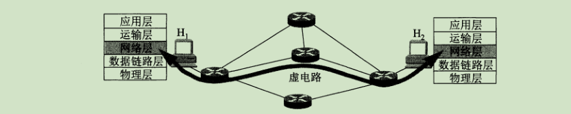
Connection-oriented communication means that the connection is established before the two parties communicate (that is, a virtual circuit is established in the packet exchange) to reserve all the network resources required for the communication between the two parties. Grouping, the need to release the established virtual circuit after the communication. This mode is based on the telecommunications network communication. As shown in the figure, the packets exchanged between the hosts H1 and H2 must be transmitted on the virtual circuit established in advance.
- Connectionless
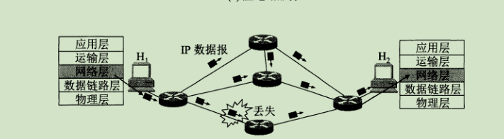
connectionless communication means that there is no need to establish a connection when sending packets. Each packet is sent independently, regardless of the packets before and after it. This transmission method is not reliable. As shown in the figure, when exchanging packets between hosts H1 and H2, each packet may select a different link for transmission, and the order of arrival may be different.
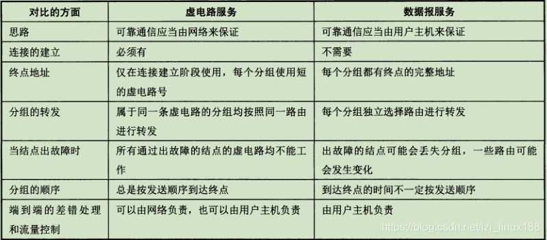
The figure below is a comparison between connection-oriented and connectionless.
Today's network layer protocols use connectionless transmission of data. That is, there is no need to establish a virtual circuit in advance to exchange packets between hosts, so the network layer does not provide a commitment to quality of service, and the network layer only provides simple, flexible, connectionless, and best-effort delivery datagram services . The reason why the connectionless method is adopted is because the host in the network system has intelligence (that is, it can handle errors), and the telephone in the traditional telecommunications network does not have a capability. Furthermore, the use of a connectionless method can save costs and the operation mode is very flexible, and can adapt to a variety of applications.
It can be seen from the above that the data packets in the network use connectionless switching at the network layer, so there are differences between various networks (such as different network types, such as Ethernet, token ring network, wireless network, etc .; The addressing scheme and routing may also be different), how does the data communicate? This is handled in this way, ** The computer networks participating in the interconnection use the same Internet protocol IP, so the computer network after interconnection can be regarded as a virtual interconnection network (virtual interconnection network is also a logical interconnection network) ** The difference between the various physical networks interconnected in this way originally existed objectively, but we can use the IP protocol to make these networks with different performances look like a unified network at the network layer (ignoring the various Specific heterogeneous details of the physical network).
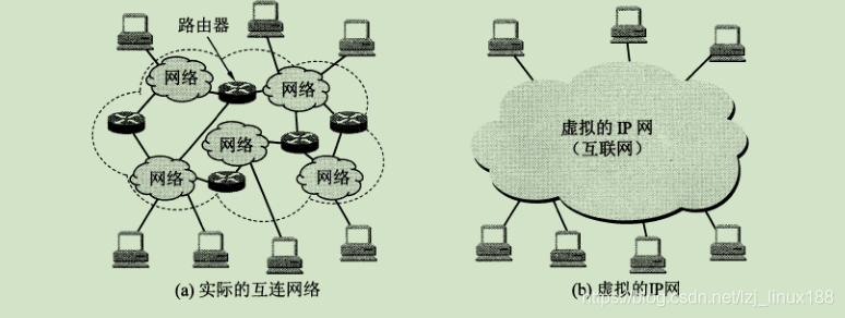
When many heterogeneous networks are interconnected by routers, if all networks use the same IP protocol, it is very convenient to discuss issues at the network layer. As shown in the figure, host H1 wants to send an IP datagram to destination host H2, although there are different physical networks, such as satellite links, wireless links, and optical cables. But all use IP protocol, so they can communicate normally.
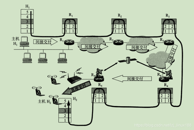
When communicating in the Internet, how does the packet identify the destination host in the network? How can the packet sent by H1 in the above figure identify H2? An important concept in communication is the device address. Assign a unique address to each device on the network so that the group knows which device to hand to. It is called an IP address in the network layer. IP address is to assign a 32-bit identifier that is unique in the world to each interface of each host (or router) on the Internet (because the IP address is 32-bit, it will use dots in writing Described in decimal ). The structure of the IP address allows us to easily address on the Internet. You need to apply to the ISP to use the public IP.
IP address classification
The addressing method of IP addresses has gone through three historical stages.
Classified IP address
Initially, it was considered that the various networks are very different, and some networks have many hosts, while some have few hosts, so the IP addresses are divided into A, B, and C categories to better satisfy different users. Claim.
The classified IP address is to divide the IP address into several fixed categories (A, B, C, D, E five categories), each category is composed of two fixed-length fields, namely the network number and host number. The network number indicates the network to which the host is connected, and the host number indicates the host (also unique) in the network.
The classification is as follows, where ABC is unicast, D is multicast and class E addresses are reserved for future use. All 0s
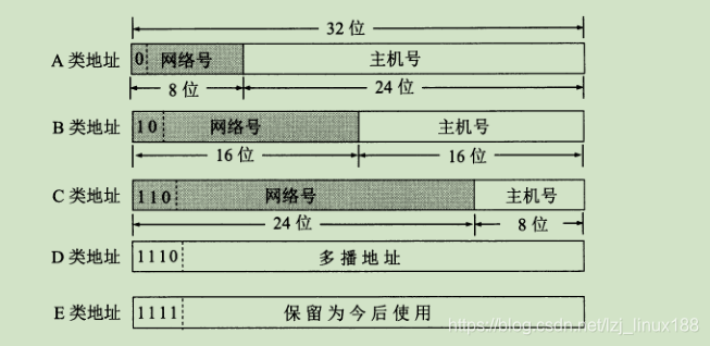
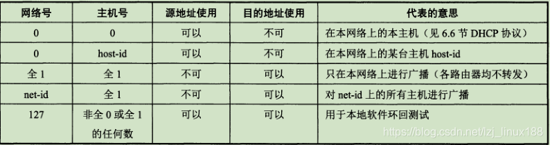
in the IP address means "this", and an IP address with a network number field of all 0s is a reserved address, meaning "this network" . The network number 127 is reserved for local software loopback testing. If the host number is all 0s, it refers to the network address , and all 1s means all, that is, the broadcast address.
Class A addresses are not assigned 127, Class B IP networks 128.0.0.0 are not assigned, Class C IP networks 192.0.0.0 are not assigned , and the special addresses in the network are shown in the following table:
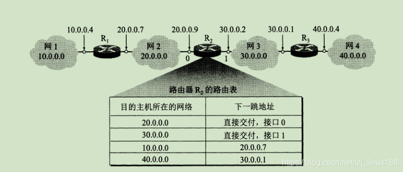
IP addresses use a hierarchical address structure to facilitate IP Address management (the reason is that the management organization only assigns network numbers, and the host number is managed internally by the company), the same router only forwards packets based on the network number of the destination host, which reduces the storage space occupied by the routing table and The time to find the routing table.Use network numbers to identify different networks. A network refers to a collection of hosts with the same network number net-id. Several LANs connected by repeaters and bridges are still a network, and LANs with different network numbers must be interconnected using routers. The following figure is the Internet where three LANs are connected by routers.

Subnetting
The utilization rate of IP addresses in the two-level structure classification mentioned above is sometimes very low . For example, the number of hosts that can be connected to a class A address network exceeds 10 million. What is this concept? How many companies have such a scale, the B-type network can also be assigned to 60,000 host numbers, and the C-type has more than 200, many companies have applied for the B-type but not used so much; assign one to each physical network The network number will make the routing table too large and affect the network performance; the two-level IP address is not flexible enough; because the classified IP address has the above-mentioned defects, a solution from the two-level IP address to the third-level IP address is proposed, namely Add a subnet number field to the IP address to turn the two-level IP address into a third-level IP address. This is subnet addressing or subnet routing .
The basic idea of dividing a subnet is: borrow a few digits from the host number of the network as a subnet number to divide the physical network into several subnets . The subnet division is purely an internal matter of the unit, and the network outside the unit cannot see this network. by the number of subnets, so the outside is still the performance of a network . The IP datagram sent by an external network to a host in this network is still to find the router connected to the unit's network according to the destination network number of the IP datagram. The router then finds the destination subnet according to the destination network number and subnet number, thereby delivering data.Subnetting only subdivides the host number of the IP address without changing the original network number of the IP address. Subnetting is a matter within the unit. Only the routers connected to it will know how to divide the subnet inside the network. There are several subnets inside..
After the data on the network reaches the router connected to this network, how does it accurately deliver the data to one of the many subnets? Since neither IP nor packet headers have a field about subnets, it needs to be distinguished by something else. This is the subnet mask . After the router receives the data from the external network, it can obtain the network address by performing the operation of the destination IP and the subnet mask, so as to know which subnet to send the data to, and the router has it. The network address and subnet mask of all connected subnets. If the network does not divide the subnet, the subnet source code uses the default mask (that is, 1 with the same number of digits as the network number) .
Packet forwarding when using subnets
After subnetting is used, the routing table must contain the destination network address, subnet mask, and next hop address .
- Extract the destination IP address D from the header of the received datagram .
- First determine whether it is direct delivery, and check the networks directly connected to the router one by one: use the subnet mask of each network and D one by one to see whether the result matches the corresponding network address. If they match, the packet is delivered directly, and the forwarding task ends. Otherwise, it is indirect delivery.
- If there is a specific host route with destination address D in the routing table, the datagram is transmitted to the next-hop router specified in the routing table; otherwise, the next step is performed
- Match each row in the routing table to see if the destination network address matches. If it matches, send the datagram to the next-hop router specified by the row; otherwise, perform the next step
- If there is a default route in the routing table, send the datagram to the default router specified in the routing table; otherwise, go to the next step
- Report error in forwarding packets.
Constitute a supernet (no classification addressing)
Partitioning subnets has alleviated the difficulties encountered by the Internet in the development, but there are still many problems that have not been dealt with. If the routing table entry is too large, there is still a waste of IP address usage, so a non-classified addressing scheme is further proposed.
The unclassified addressing method is developed on the variable-length subnet mask VLSM. The official name is the unclassified inter-domain routing CIDR . Its main feature is the elimination of the traditional A, B, and C types of addresses and the division of subnets. The concept of can more effectively allocate IP address space . CIDR divides the IP address into two parts: network prefix and host number, and then returns to two-level addressing. CIDR consists of consecutive IP addresses with the same network prefix to form a CIDR address block . As long as we know any address in the CIDR address block, we can know the starting address and the maximum address of this address block, and the number of addresses in the address block. The specific algorithm is that the host number is all 0 is the smallest IP address, and the host number is all 1 is the largest IP address. At the same time, CIDR also uses the slash notation, adding a slash "/" after the IP address, followed by the number of bits occupied by the network prefix .Please note that CIDR does not use subnets, which means that CIDR does not specify several bits in the 32-bit address as subnet fields, but the unit assigned to a CIDR address block can still divide some subnets according to needs in this unit These subnets also have only one network first and one host number field.
Using the CIDR address block, the CIDR address block is used in the routing table to find the destination network. This type of address aggregation is often called route aggregation . It allows an item in the routing table to represent many routes of the original traditional classification address. The routing table The number of projects in this category can therefore be reduced a lot. Route aggregation is also referred to as forming a supernet.
When using CIDR, because of the notation of network prefix, the IP address is composed of two parts: network prefix and host number, so the entries in the routing table should also be changed accordingly. At this time, each item consists of the network prefix and the next hop. However, more than one matching result may be obtained when looking up the routing table, so the route with the longest network prefix should be selected from the matching results . Use binary clues when looking up routes in the routing table. Readers who are interested in specific usage can download it under Baidu.
Data packet transmission process in the network
The transmission of data packets in the network is forwarded by the network as a unit. The purpose of this is to simplify the routing table items in the router (if it is forwarded according to the host IP, the entries in the routing table will be very large) After receiving the packet, the router first looks up the routing table to see if it can be delivered directly to the network connected to the router, if it can be delivered directly; otherwise it is forwarded to another router, because the router and the router are connected to the same network, so Forwarding packets to other routers is very easy and realistic (only need ARP protocol to achieve).The forwarding of the packet is based on the destination network address to determine the next hop. The IP datagram will eventually find the router on the destination network where the destination host is located (it may require multiple indirect delivery). Only when it reaches the last router, it tries to Direct delivery to the destination host.
Although the Internet performs packet forwarding based on the network where the destination host is located, network administrators can more easily control the network and test the network and security considerations, so you can also specify a route for the destination host, that is, a specific host route .
The router can also use the default route to reduce the space occupied by the routing table and the time it takes to search the routing table. This forwarding method is very useful when a network has few external connections. The default route often shows its benefits when the host sends IP datagrams. The host must look up its own routing table when sending each IP datagram. If a host is connected to a small network, and this network uses only one Router and Internet connection, then in this case it is very appropriate to use the default route. As shown in the figure below, any host on the N1 network only needs three items. The destination host connected to N1 can be delivered directly, and the destination host is forwarded to R2 in N2, otherwise it will be handed over to R1. In the actual router table, the "other" and "direct" characters do not appear, but are recorded as 0.0.0.0 ( this network )

router packet forwarding algorithm is as follows:
- Extracted from the destination host IP address of the datagram header portion D , the destination network address obtained N .
- If N is a network address directly connected to this router, direct delivery is performed without passing through other routers; otherwise, it is indirect delivery and the next step is performed.
- If there is a specific host route whose destination address is D in the routing table, the datagram is transmitted to the next-hop router specified in the routing table; otherwise, the next step is performed.
- If there is a route to network N in the routing table , the datagram is transmitted to the next-hop router specified in the routing table; otherwise, the next step is performed.
- If there is a default route in the routing table, the datagram is transmitted to the default router indicated in the routing table; otherwise, the next step is performed.
- Report error in forwarding packets.
One thing to note is that there is no place in the header of the IP datagram that can be used to indicate the "IP address of the next-hop router". Only the source and destination IP addresses are written in the header of the IP datagram, and there is no intermediate The IP address of the passing router. So how can the datagram to be forwarded find the next-hop router?After receiving a datagram to be forwarded, the router searches the routing table for the route and obtains the IP address of the next-hop router. Then forward it to the corresponding router. Similarly, the routing table does not indicate the complete path of the given packet to a network. The routing table only indicates that when a network is reached, it should go to a router first, and then continue to find the routing table after reaching the next-hop router. Look down until you finally reach the destination network.
ARP protocol
In the previous study, I learned that the IP layer and above use IP addresses, and the data link layer uses hardware addresses (ie, MAC addresses), as shown

in the following figure: When sending data, the data goes from the upper layer to the lower layer. Then it is transmitted on the communication link. Once the datagram using the IP address is handed over to the data link layer, it is encapsulated into a MAC frame. The source and destination addresses used in the transmission of the MAC frame are both hardware addresses. After the device receives the correct frame, only after stripping the header and tail of the MAC frame to the MAC layer data, the network layer can find the source IP address and destination IP in the header of the IP datagram address.
** In short, the IP address is placed in the header of the IP datagram, and the hardware address is placed in the header of the MAC frame. When the IP datagram is placed in the MAC frame of the data link layer, the entire IP datagram becomes the data of the MAC, so the IP address of the datagram cannot be seen at the data link layer **。
During the transmission of the IP datagram, the source IP address and the destination IP address will never change, but the MAC address may change during the transmission. This is because the MAC address is different when it is transmitted on different links. Therefore, in data transmission, we also need to know the MAC address of the device, and the format of the MAC address and the IP address is inconsistent, and a simple mapping cannot be established. So how to get the MAC address of the device during transmission?
For the above problem, the ARP protocol is used in the network to obtain the MAC address of the device. Here, since the IP protocol uses the ARP protocol, the ARP protocol is usually classified into the network layer.

** The working principle of ARP: ** The network layer uses an IP address, but when transmitting data frames on the link of the actual network, the network hardware address must eventually be used. Therefore, an ARP cache is required in the host to store the mapping table of each device's IP address to hardware address. When device A wants to send a message to device B, the ARP workflow is as follows:
- First, check whether the IP address of host B is in the ARP cache of device A. If yes, use the hardware address in the cache directly. Otherwise go to the next step
- The ARP process of device A broadcasts an ARP request packet on the local area network, and sends out its IP address, MAC address, and IP address of the device to be found.
- All hosts on the local area network can receive the ARP request packet. Only when the IP address in the host matches the IP address to be queried in the ARP request packet will the device accept the ARP packet and send an ARP response to host A. Other devices do not respond. At the same time, host B will record the IP address and MAC address of device A in the ARP cache table.
- After receiving the ARP response packet from host B, host A will also write the mapping of host B's IP address to hardware address in the ARP cache.
The ARP cache in the device is still very useful. Using the ARP cache can reduce the amount of traffic on the network (you do not need to send an ARP request every time you transmit a data packet). At the same time, ARP sets a survival time for each mapped address item stored in the cache. Any items that exceed the survival time are deleted from the cache (the purpose is to consider the replacement of the network adapter in the network, and the MAC address needs to be updated after the network adapter is replaced. ).
ARP is to solve the problem of mapping the IP addresses and hardware addresses of hosts or routers on the same local area network. If they are not on the same local area network, they cannot be resolved. In this case, a router is needed to obtain the MAC address of the host in the same local area network.
You can communicate using a MAC address. Why do you need an IP address?
Since there are various networks all over the world, they use different hardware addresses. To enable these heterogeneous networks to communicate with each other, very complex hardware address translation must be performed. Therefore, using the same IP addressing to deal with this complex problem, so that their communication is as simple and convenient as connecting to the same network (shielding the differences of various heterogeneous hardware).
IP datagram format
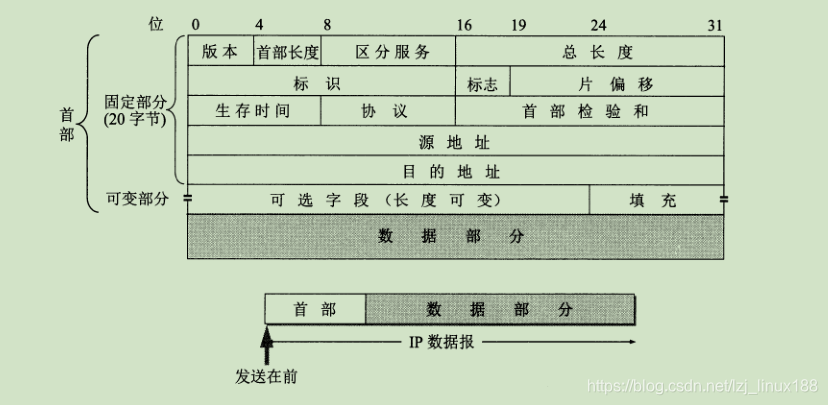
The format of the IP datagram is as above, the following is a brief introduction to each field
- Version: refers to the version of the IP protocol, and the version number of IPv4 is 4
- Header length: refers to the length of the IP header, the unit is a 32-bit word. The length is between 20 ~ 60 bytes
- Differentiated services: Also known as service types, they are not normally used.
- Total length: the length of the sum of the header and data, in bytes. The maximum length of the datagram is 2 16 -1, or 65535 bytes.
- Identification: The IP software maintains a counter in the memory. Each time a datagram is generated, the counter is incremented by 1, and this value is assigned to the identification field. When the length of the datagram exceeds the MTU of the network and must be fragmented, the value of this identification field is copied into the identification field of all datagram fragments. The value of the same identification field enables each fragmented datagram to be correctly reassembled into the original datagram .
- Flag: the lowest bit MF (more fragment), MF = 1 means that there are fragments of datagrams behind; MF = 0 means that this is the last
flag of several datagram fragments. The middle bit DF (don't fragment) means It is not possible to fragment, and fragmentation is only allowed when DF = 0. - Slice Offset: The relative position of a slice in the original packet after the fragmentation of a longer packet. Relative to the starting point of the user field, where does the slice start. The unit is 8 bytes
- Time-to-live: indicates the lifetime of the datagram in the network. This field is set by the source of the data sent. The router decrements the TTL value by 1 before forwarding the datagram. If the TTL value decreases to zero, the datagram is discarded , No longer forward
- Protocol: The protocol field indicates which protocol is used for the data carried in this datagram.

- Header Checksum: This field only checks the header of the datagram, but does not include the data portion. This can reduce the workload of calculation.
- source address
- Destination address
- The variable part of the IP datagram header.
In the IP protocol, there is the total length of IP data packets, but each data link layer protocol below the IP layer specifies the maximum length (MTU) of the data field in a data frame. When an IP datagram is encapsulated into When linking frames, the total length of this datagram must not exceed the MTU value. If the length of the transmitted datagram exceeds the MTU value of the data link layer, the excessively long datagram must be fragmented.
Internet Control Message Protocol ICMP
ICMP allows hosts or routers to report error conditions and provide reports on abnormal conditions. The ICMP protocol belongs to the IP layer protocol. The ICMP message is used as the data of the IP layer datagram, plus the header of the datagram, to form an IP datagram and send it out. The message format is as follows:
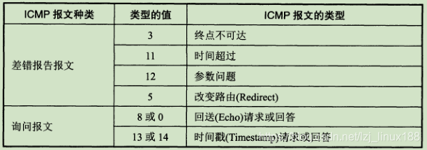
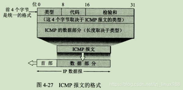 ICMP messages are divided into ICMP error report messages and ICMP query messages. The code field of the ICMP message is to further distinguish several different situations in a certain type. The checksum field is used to check the entire ICMP message. .
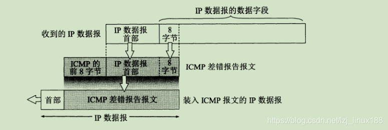
The data fields in all ICMP error report messages have the same format . The header of the received IP datagram for error reporting and the first 8 bytes of the data field are extracted as the data field of the ICMP message . The first 8 bytes of the data field of the received datagram are extracted in order to obtain the port number of the transport layer and the transmission sequence number of the transport message. This information is useful for the source point to notify the high-level protocol.
IP multicast
Multicasting is the transmission of data from one source to many destinations, that is, one-to-many communication. Multicast communication can reduce the amount of data traffic on the network. Of course, multicast also needs to use the multicast IP address for communication.
We know that every host on the Internet must have a globally unique IP address. So how can the host receive packets from a particular multicast group? Obviously the destination address of this multicast datagram must not be written to the IP address of this host. This is because tens of thousands of hosts may join the same multicast group at the same time. Multicast datagrams cannot write so many host IP addresses in their headers. In the destination address of the multicast datagram, the identifier of the multicast group (that is, the multicast address) is written, and then the IP address of the host joining the multicast group is managed to be associated with the identifier of the multicast group.
The identifier of the multicast group is the class D address in the IP address. The association mentioned above is achieved through the Internet Group Management Protocol IGMP. So the difference between a multicast datagram and a general IP datagram is that it uses a Class D IP address as the destination address, and the value of the protocol field in the header is 2, indicating that the Internet Group Management Protocol IGMP is used. Multicast addresses can only be used for destination addresses, not source addresses, and no ICMP error messages are generated for multicast datagrams.
Hardware multicast on LAN
The multicast hardware address range is 01-00-5E-00-00-00 to 01-00-5E-7F-FF-FF. Since the upper 24 bits of the hardware address are used as company logos, only the lower 24 bits can be freely assigned , Plus the 23rd place can only be 0 (this is for historical reasons, at that time I only bought 1 OUI and only allocated half for multicast. Still poverty limits imagination ^ _ ^), so only 23 can be used Bit. The correspondence between the multicast hardware address and the multicast IP address is that the lower 23 bits of the MAC address use the lower 23 bits of the IP multicast address. As shown below, so this mapping relationship is not unique.

The local use scope of the IGMP protocol. IGMP is not a protocol for managing all multicast group members within the Internet. IGMP does not know the number of members included in an IP multicast group, or on which networks these members are distributed, and so on. The IGMP protocol is to let the multicast router connected to the local LAN know whether a host on this LAN has joined or left a multicast group .
IGMP also uses IP datagrams to transmit its messages, that is, IGMP messages plus IP headers constitute IP datagrams, so IGMP is also a component of the Internet Protocol IP.
