table of Contents
- 1.Objectives:
- 2.Experiment Content:
- 3.Experiment Principle:
- 4.Experiment Steps Result and Conlusion:
- 1, binary image morphological transformation of
- 2, the input image morphological operations, i.e. erosion, dilation, opening operation and closing operation, changing the structure of the element shape, size, redo the above experiments, the results of comparative experiments, the influence of the operation of the element analysis of the structure;
- 3 to FIG FigP0936 (bubbles_on_black_background) .tif Example complete functions are the following:
- [Appendix] implementation code
- PS: I am a research note on Mathematical Morphology
1.Objectives:
1. Study MATLAB binary morphological image processing algorithms used utilization;
2. Mastering basic morphological image processing operations MATLAB function;
3. Learn basic applications morphology.
2.Experiment Content:
1. Programming binary image substantially morphological (erosion, dilation, opening operation and closing operation); selecting a different filter structure element image of the object.
2. To achieve smooth gray scale image noise and image edge extracted by the morphology operation.
3.Experiment Principle:
See the book.
4.Experiment Steps Result and Conlusion:
1, binary image morphological transformation of
Need to write binary image morphological transformation function:
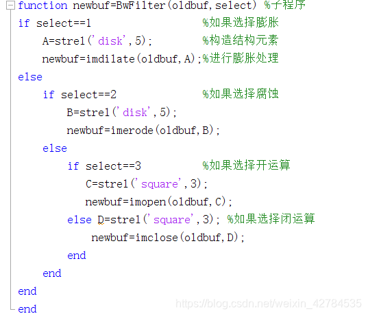
functionnewbuf = BwFilter (oldbuf, select) on the expansion of the MATLAB function call, the correlation function and the image corrosion screening algorithms, the corresponding binary image processing, the final result is stored in the array newbuf. Programming BwFilter () function function. Structural elements can also be created with ones and zeros function function.
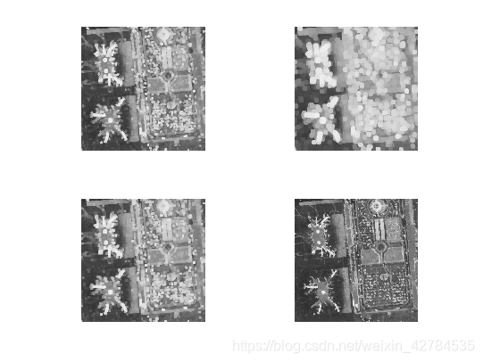
2, the input image morphological operations, i.e. erosion, dilation, opening operation and closing operation, changing the structure of the element shape, size, redo the above experiments, the results of comparative experiments, the influence of the operation of the element analysis of the structure;
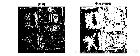
FIG expander 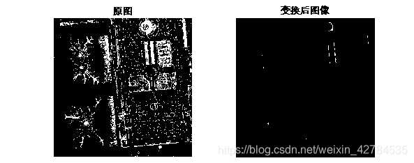 2 Corrosion
 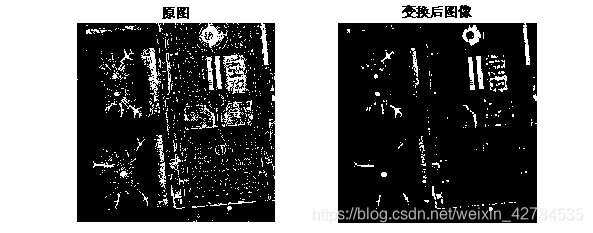 FIG opening operation 3
 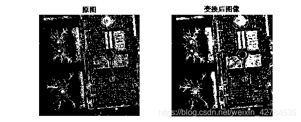 in FIG. 4 closing operation
Conv: Compared to the original image, as a result of erosion as before to make each dollar ratio becomes smaller, so useful for removing noise peak. The result will be expanded gradation value such that each pixel becomes larger than the previous element, it is suitable for removing low noise. However, since this experiment too much loss of the original image, so that the expansion of the larger particles, only particles less after etching.
= Erosion operation to opening operation, a dilation operation then (looks fine linked to two separated target). I.e. segmented image.
= First dilation operation and closing operation, and then etching operation (block together two closure looks fine connection). That make the image more fulfilling.
Structuring element shape changes, the size of the effect:
(1) Expansion
(2) Corrosion  opening operation
 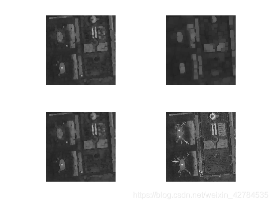 and closing operation
 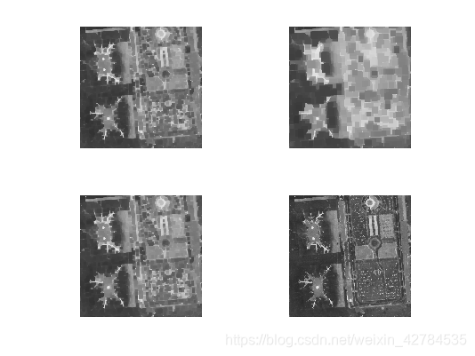 Conv: changing the shape and size of the structure element, respectively, using a Type 'disk', 'square', 'ones' and custom matrix, etc., determined by the size parameter. To expand, for example, can be seen under the same type of structural element size is increased, more severe white spots partially expanded, and different types and degree of expansion of different directions. For etching the image to be corroded, the image for the opening operation is interrupted thin connecting portion, the greater the size of structural parameters, the less white image portion; For closing operation, increased image connection, the white portion becomes large and blurred, the same size increases, a deeper level, different types of effects.
3 to FIG FigP0936 (bubbles_on_black_background) .tif Example complete functions are the following:
(1) Extraction and particles fused image boundary
(2) overlap each other to extract the particles
(3) do not overlap the extracted particles
Note: (1) area filling algorithms may be utilized. As shown in FIG source image, the image can be converted to a binary image, and then subjected to inverted, so that the results for area fill particles (closing operation) will be connected to the boundary, and then compared with the source image, particle image can be derived in the source image boundary connected.
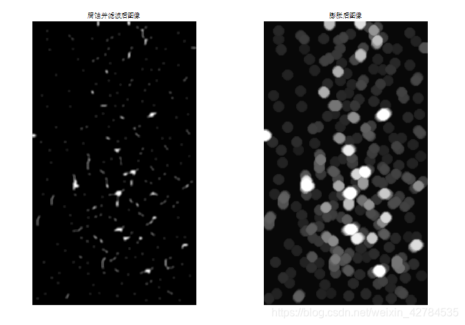
(2) by etching the image expansion operation. Template image for the first etching operation, due to the inevitable overlap of particles larger than the area of individual particles, thus remaining part after the etching operation for the overlapping portions of the particles, and then be expanded (open operation) with which the the image source operation are compared, it can be concluded particle image overlap.
(3) after overlapping the particles obtained by subtracting its source image, the resulting image is independent particle distribution
(. 1) 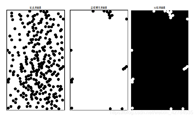 (2) (3)
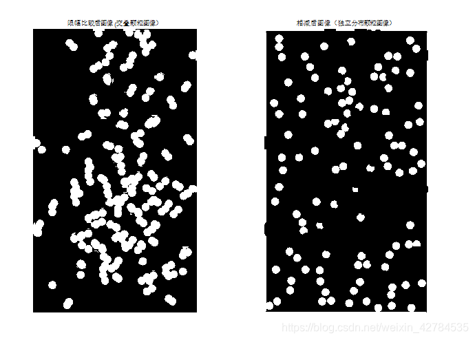 Conv: (. 1) on the original image is filled, may be significantly to the original white point observed increases on the original image to achieve the effect of noise filtering. (2) to the erosion operation on the original image, and then a dilation operation (looks fine linked to two separated target). The main image is divided i.e. opening operation. (3) After subtracting out was small particles i.e. particles dispersed FIG.
[Appendix] implementation code
A program
function newbuf=BwFilter(oldbuf,select) %子程序
if select==1                  %如果选择膨胀
   A=strel('disk',5);        %构造结构元素
   newbuf=imdilate(oldbuf,A);%进行膨胀处理
else
    if select==2              %如果选择腐蚀
       B=strel('disk',5);
       newbuf=imerode(oldbuf,B);
    else
        if select==3          %如果选择开运算
          C=strel('square',3);
          newbuf=imopen(oldbuf,C);
        else D=strel('square',3); %如果选择闭运算
            newbuf=imclose(oldbuf,D);
        end
    end
end
end
Procedure 2
clear all;clc;
addpath('E:\数字图像处理\程序与图像\dipum_toolbox_2.0.2(only run)');%添加相应的.p文件
f=imread('lax.tif'); %读图像
m=input(''); %输入select种类,1代表膨胀,2代表腐蚀,3代表开运算,4代表闭运算

f1=im2bw(f);       %将图像转化为二值图像
f2=BwFilter(f1,m); %调用BwFilter子函数进行处理
subplot(121)       %显示原图(二值图像)
imshow(f1);
title('原图');
subplot(122)       %显示转化后图像imshow(f2);title('变换后图像');
Procedure 3
clear all;clc;close all;                   %清空图像,释放变量
f=imread('FigP0936(bubbles_on_black_background).tif');%读图像
f1=im2bw(f);                               %转化为二值图像
f2=~f1;                                    %对图像取反
figure;imshow(f2);title('取反后图像');     %显示取反图像
f3=imfill(f2,'holes');                     %调用函数进行区域填充
figure;imshow(f3);title('区域填充后图像'); %显示区域填充后图像
g=f;                                       %使g等于f图像
[m,n]=size(g);        %取g图像的大小
for i=1:m             %将区域填充的结果与原图进行逐点比较,若该点在填充结果时为白,这点在g图像中便记为黑
    for j=1:n
        if f3(i,j)==1
            g(i,j)=0;
        end
    end
end
figure;imshow(g);title('比较后图像');  %得到与边界相连的颗粒图像

clear all;clc;
addpath('E:\数字图像处理\程序与图像\dipum_toolbox_2.0.2(only run)');%添加相应的.p文件
f=imread('FigP0936(bubbles_on_black_background).tif');%读图像
mask1=strel(ones(15,15));  %用ones函数构造结构元素
mask1f2=imerode(f,mask1);       %对原图进行腐蚀处理
f3=filter2(fspecial('average',7),im2double(f2));%对腐蚀处理后结果进行滤波,滤波器形式由fspecial定义
f3=medfilt2(f3);           %进行中值滤波
f3=im2uint8(f3);           %将滤波后结果转化为无符号八位整型形式
figure;
imshow(f3);title('腐蚀并滤波后图像');%显示腐蚀并滤波后图像
mask2=strel('ball',12,12); %构造结构元素mask2
f4=imdilate(f3,mask2);     %再进行膨胀处理
figure;imshow(f4);title('膨胀后图像');%显示膨胀后图像
f5=f;                      %使f5等于f
[m,n]=size(f);             %得到原图的大小
for i=1:m                  %逐点比较处理后图像与原图,并做限幅处理,处理后图像中小于等于40的,一律省去,大于该值的取原图中的白点
    for j=1:n
        if f4(i,j)<=40
           f5(i,j)=0;
        else            f5(i,j)=f(i,j);
        end
    end
end

figure;imshow(f5);title('限幅比较后图像(交叠颗粒图像)');%显示交叠图像颗粒图
f6=f-f5;                   %将原图和交叠图像相减,得到独立分布颗粒图像
figure;imshow(f6);title('相减后图像(独立分布颗粒图像)');%显示独立分布颗粒图
PS: I am a research note on Mathematical Morphology
https://blog.csdn.net/weixin_42784535/article/details/105125411
