文章目录
前言
- 硬件:stm32f103c8t6 核心板
- 软件:STM32CubeMX 6.4.0
- 软件:keil5 mdk
一、移植RT-thread Nano
1、STM32CubeMX 安装 RT-Thread
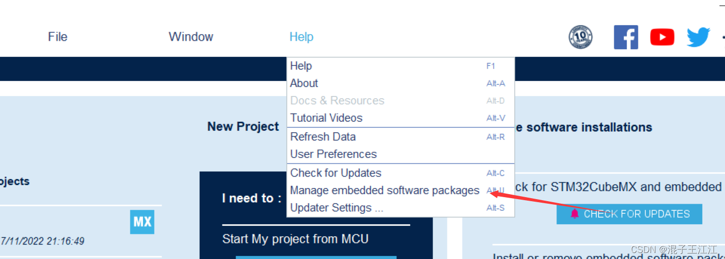
打开STM32CubeMX
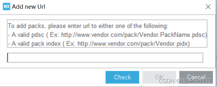
- 软件包地址:
https://www.rt-thread.org/download/cube/RealThread.RT-Thread.pdsc
点击help---->Manage embedded software packages
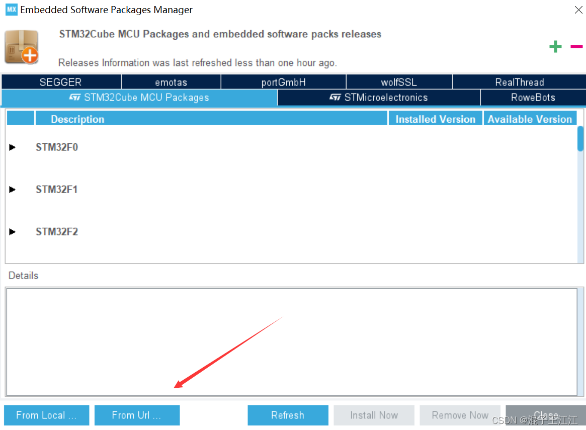
点击 From Url---->User Defined Packs Manager
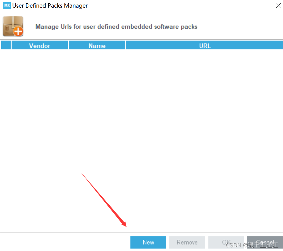
点击new进行添加
填入上面的网址,然后点击 check
等待下载!
回到上一步,选择RealThread,选中下方的方框进行install,下载成功显示绿色
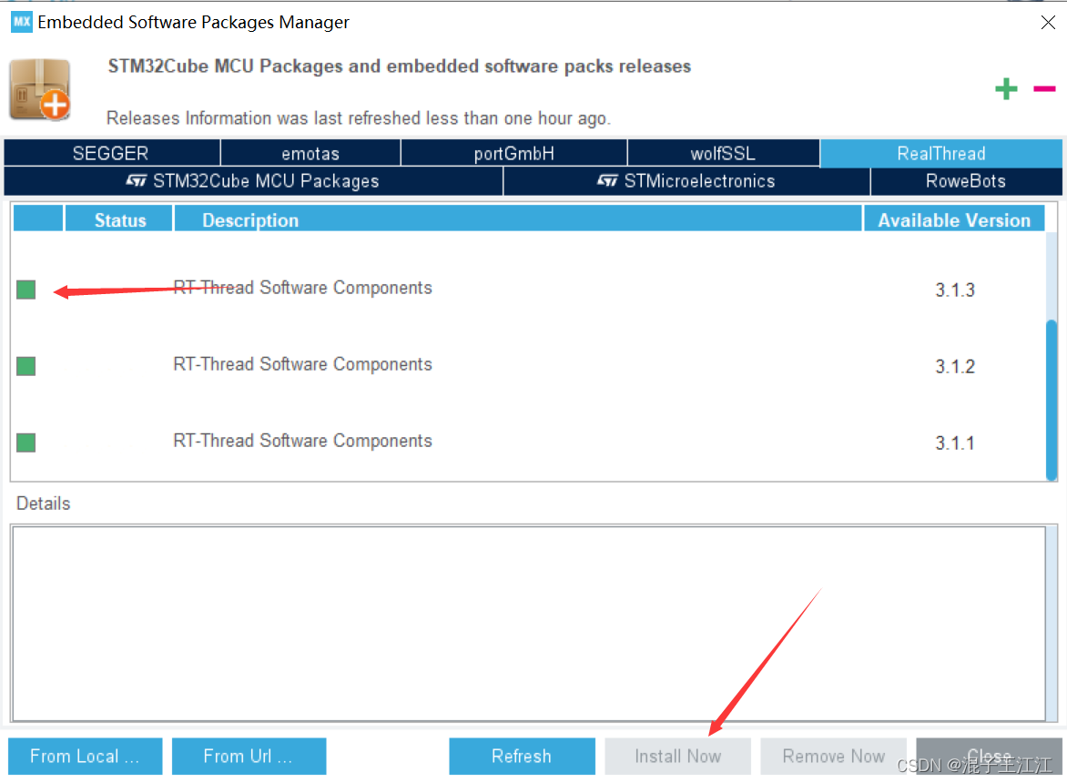
安装过程中一路agree即可。
2、Keil安装RT-Thread
打开keil
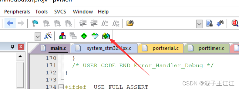
点击install然后agree等待下载
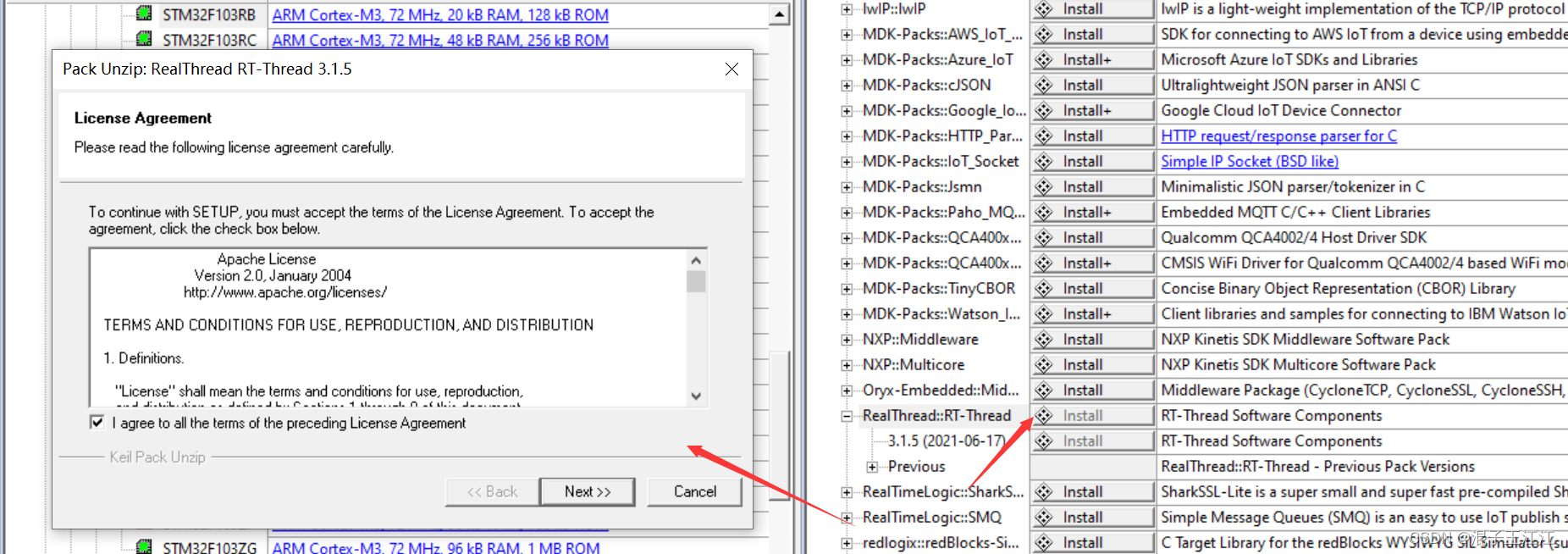
出现下面的情况即可

二、STM32CubeMX 创建工程
选择相对应的芯片型号,创建new project:
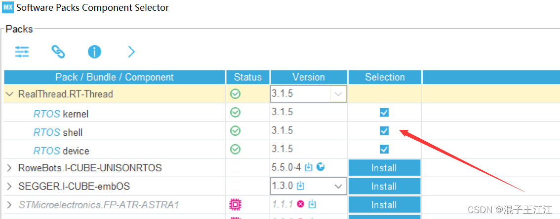
1.添加RT-Thread组件
Softwares Packages->Select Components
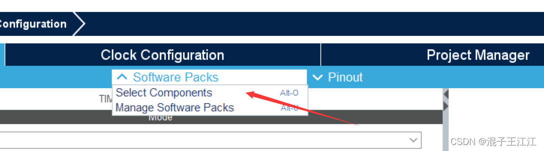
勾选
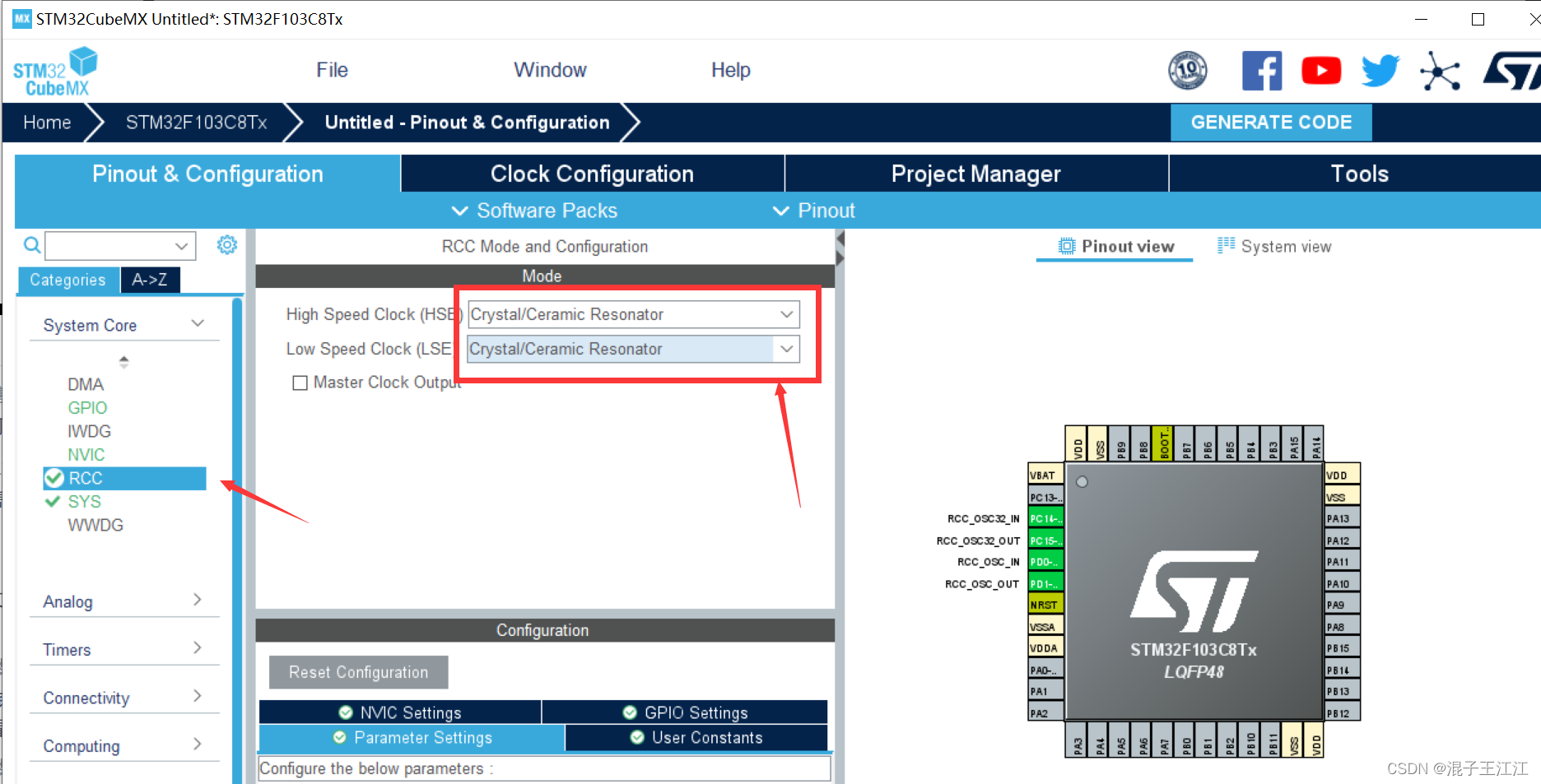
2、配置项目
RCC
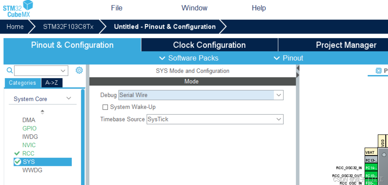
sys
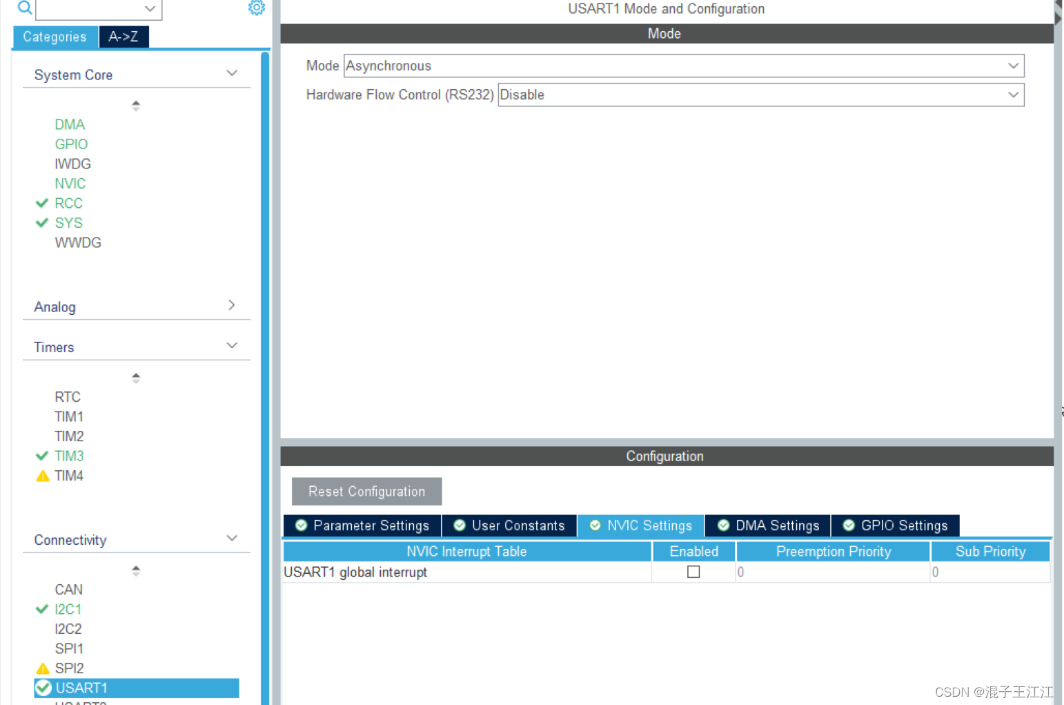
uart
I2C

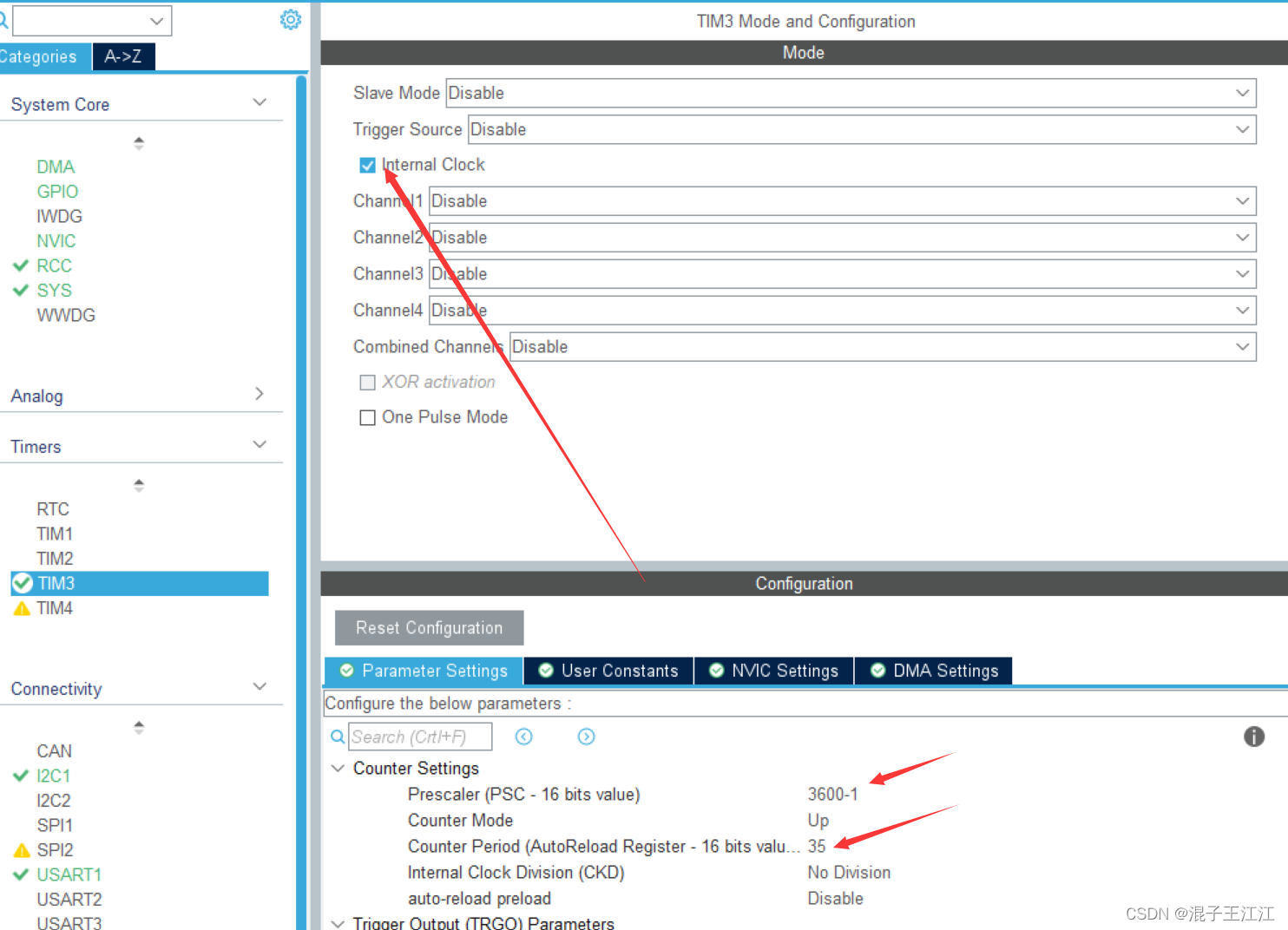
Tim3
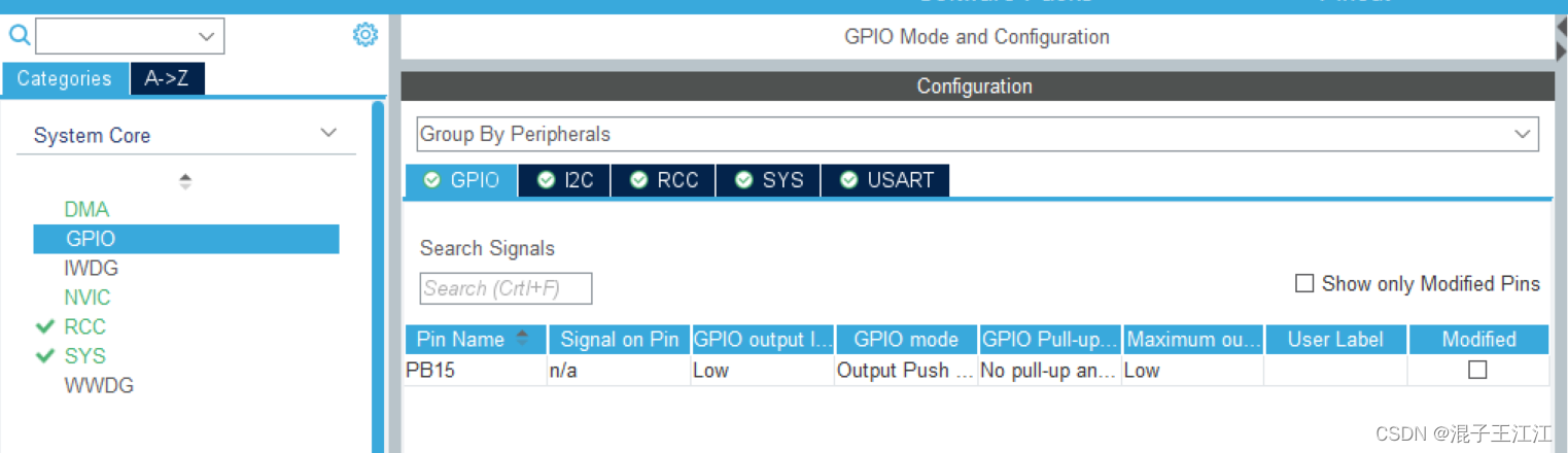
GPIO设置PB15控制灯亮
NVIC

RT-Thread 操作系统重定义 HardFault_Handler、PendSV_Handler、SysTick_Handler 中断函数,为了避免重复定义的问题,在生成工程之前,需要在中断配置中,代码生成的选项中,取消选择三个中断函数(对应注释选项是 Hard fault interrupt, Pendable request, Time base :System tick timer)
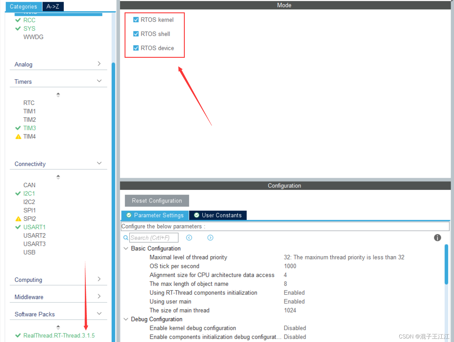
勾选RTOS
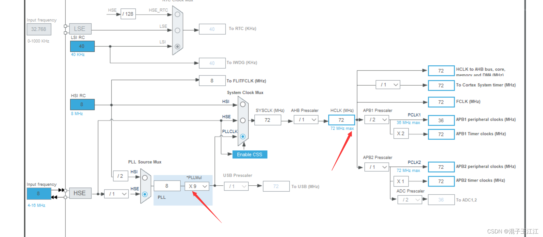
时钟树
设置工程路径、工程名,最后导出文件。使用keil打开并进行编写。
三、keil配置
1、ANT20配置
在项目路径下,新建一个AHT20文件夹,并在文件夹下新建两个文件:
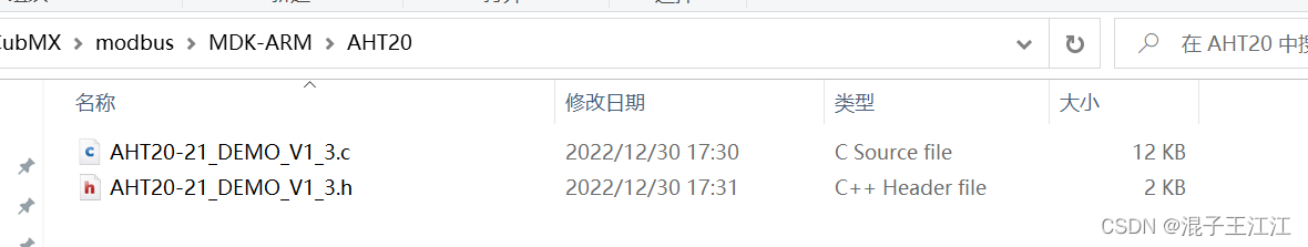
AHT20-21_DEMO_V1_3.c文件:
/*******************************************/
/*@版权所有:广州奥松电子有限公司          */
/*@作者:温湿度传感器事业部                */
/*@版本:V1.2                              */
/*******************************************/
//#include "main.h"
#include "AHT20-21_DEMO_V1_3.h"
#include "gpio.h"
#include "i2c.h"


void Delay_N10us(uint32_t t)//延时函数
{


  uint32_t k;

   while(t--)
  {


    for (k = 0; k < 2; k++);//110
  }
}

void SensorDelay_us(uint32_t t)//延时函数
{


	for(t = t-2; t>0; t--)
	{


		Delay_N10us(1);
	}
}

void Delay_4us(void)		//延时函数
{


	Delay_N10us(1);
	Delay_N10us(1);
	Delay_N10us(1);
	Delay_N10us(1);
}
void Delay_5us(void)		//延时函数
{


	Delay_N10us(1);
	Delay_N10us(1);
	Delay_N10us(1);
	Delay_N10us(1);
	Delay_N10us(1);

}

void Delay_1ms(uint32_t t)		//延时函数
{


   while(t--)
  {


    SensorDelay_us(1000);//延时1ms
  }
}


//void AHT20_Clock_Init(void)		//延时函数
//{


//	RCC_APB2PeriphClockCmd(CC_APB2Periph_GPIOB,ENABLE);
//}

void SDA_Pin_Output_High(void)   //将PB7配置为输出 , 并设置为高电平, PB7作为I2C的SDA
{


	GPIO_InitTypeDef  GPIO_InitStruct;
	GPIO_InitStruct.Mode = GPIO_MODE_OUTPUT_PP;//推挽输出
	GPIO_InitStruct.Pin = GPIO_PIN_7;
	GPIO_InitStruct.Speed = GPIO_SPEED_FREQ_HIGH;
	HAL_GPIO_Init(GPIOB,& GPIO_InitStruct);
	HAL_GPIO_WritePin(GPIOB,GPIO_PIN_7,GPIO_PIN_SET);
}

void SDA_Pin_Output_Low(void)  //将P7配置为输出  并设置为低电平
{


	GPIO_InitTypeDef  GPIO_InitStruct;
	GPIO_InitStruct.Mode = GPIO_MODE_OUTPUT_PP;//推挽输出
	GPIO_InitStruct.Pin = GPIO_PIN_7;
	GPIO_InitStruct.Speed = GPIO_SPEED_FREQ_HIGH;
	HAL_GPIO_Init(GPIOB,& GPIO_InitStruct);
	HAL_GPIO_WritePin(GPIOB,GPIO_PIN_7,GPIO_PIN_RESET);
}

void SDA_Pin_IN_FLOATING(void)  //SDA配置为浮空输入
{


	GPIO_InitTypeDef  GPIO_InitStruct;
	GPIO_InitStruct.Mode = GPIO_MODE_INPUT;//浮空
	GPIO_InitStruct.Pin = GPIO_PIN_7;
	GPIO_InitStruct.Speed = GPIO_SPEED_FREQ_HIGH;
	HAL_GPIO_Init( GPIOB,&GPIO_InitStruct);
}


void SCL_Pin_Output_High(void) //SCL输出高电平,P14作为I2C的SCL
{


	HAL_GPIO_WritePin(GPIOB,GPIO_PIN_6,GPIO_PIN_SET);
}

void SCL_Pin_Output_Low(void) //SCL输出低电平
{


	HAL_GPIO_WritePin(GPIOB,GPIO_PIN_6,GPIO_PIN_RESET);
}

void Init_I2C_Sensor_Port(void) //初始化I2C接口,输出为高电平
{


	GPIO_InitTypeDef  GPIO_InitStruct;
	GPIO_InitStruct.Mode = GPIO_MODE_OUTPUT_PP;//推挽输出
	GPIO_InitStruct.Pin = GPIO_PIN_7;
	GPIO_InitStruct.Speed = GPIO_SPEED_FREQ_HIGH;
	HAL_GPIO_Init(GPIOB,& GPIO_InitStruct);
	HAL_GPIO_WritePin(GPIOB,GPIO_PIN_15,GPIO_PIN_SET);


	GPIO_InitStruct.Mode = GPIO_MODE_OUTPUT_PP;//推挽输出
	GPIO_InitStruct.Pin = GPIO_PIN_6;
	GPIO_InitStruct.Speed = GPIO_SPEED_FREQ_HIGH;
	HAL_GPIO_Init(GPIOB,& GPIO_InitStruct);
	HAL_GPIO_WritePin(GPIOB,GPIO_PIN_15,GPIO_PIN_SET);

}
void I2C_Start(void)		 //I2C主机发送START信号
{


	SDA_Pin_Output_High();
	SensorDelay_us(8);
	SCL_Pin_Output_High();
	SensorDelay_us(8);
	SDA_Pin_Output_Low();
	SensorDelay_us(8);
	SCL_Pin_Output_Low();
	SensorDelay_us(8);
}


void AHT20_WR_Byte(uint8_t Byte) //往AHT20写一个字节
{


	uint8_t Data,N,i;
	Data=Byte;
	i = 0x80;
	for(N=0;N<8;N++)
	{


		SCL_Pin_Output_Low();
		Delay_4us();
		if(i&Data)
		{


			SDA_Pin_Output_High();
		}
		else
		{


			SDA_Pin_Output_Low();
		}

    SCL_Pin_Output_High();
		Delay_4us();
		Data <<= 1;

	}
	SCL_Pin_Output_Low();
	SensorDelay_us(8);
	SDA_Pin_IN_FLOATING();
	SensorDelay_us(8);
}


uint8_t AHT20_RD_Byte(void)//从AHT20读取一个字节
{


		uint8_t Byte,i,a;
	Byte = 0;
	SCL_Pin_Output_Low();

	SDA_Pin_IN_FLOATING();
	SensorDelay_us(8);

	for(i=0;i<8;i++)
	{


    SCL_Pin_Output_High();

		Delay_5us();
		a=0;

		//if(GPIO_ReadInputDataBit(GPIOB,GPIO_Pin_15)) a=1;
		if(HAL_GPIO_ReadPin(GPIOB,GPIO_PIN_7)) a=1;
		Byte = (Byte<<1)|a;

		//SCL_Pin_Output_Low();
		HAL_GPIO_WritePin(GPIOB,GPIO_PIN_6,GPIO_PIN_RESET);
		Delay_5us();
	}
  SDA_Pin_IN_FLOATING();
	SensorDelay_us(8);
	return Byte;
}


uint8_t Receive_ACK(void)   //看AHT20是否有回复ACK
{


	uint16_t CNT;
	CNT = 0;
	SCL_Pin_Output_Low();
	SDA_Pin_IN_FLOATING();
	SensorDelay_us(8);
	SCL_Pin_Output_High();
	SensorDelay_us(8);
	while((HAL_GPIO_ReadPin(GPIOB,GPIO_PIN_7))  && CNT < 100)
	CNT++;
	if(CNT == 100)
	{


		return 0;
	}
 	SCL_Pin_Output_Low();
	SensorDelay_us(8);
	return 1;
}

void Send_ACK(void)		  //主机回复ACK信号
{


	SCL_Pin_Output_Low();
	SensorDelay_us(8);
	SDA_Pin_Output_Low();
	SensorDelay_us(8);
	SCL_Pin_Output_High();
	SensorDelay_us(8);
	SCL_Pin_Output_Low();
	SensorDelay_us(8);
	SDA_Pin_IN_FLOATING();
	SensorDelay_us(8);
}

void Send_NOT_ACK(void)	//主机不回复ACK
{


	SCL_Pin_Output_Low();
	SensorDelay_us(8);
	SDA_Pin_Output_High();
	SensorDelay_us(8);
	SCL_Pin_Output_High();
	SensorDelay_us(8);
	SCL_Pin_Output_Low();
	SensorDelay_us(8);
    SDA_Pin_Output_Low();
	SensorDelay_us(8);
}

void Stop_I2C(void)	  //一条协议结束
{


	SDA_Pin_Output_Low();
	SensorDelay_us(8);
	SCL_Pin_Output_High();
	SensorDelay_us(8);
	SDA_Pin_Output_High();
	SensorDelay_us(8);
}

uint8_t AHT20_Read_Status(void)//读取AHT20的状态寄存器
{


	uint8_t Byte_first;
	I2C_Start();
	AHT20_WR_Byte(0x71);
	Receive_ACK();
	Byte_first = AHT20_RD_Byte();
	Send_NOT_ACK();
	Stop_I2C();
	return Byte_first;
}

uint8_t AHT20_Read_Cal_Enable(void)  //查询cal enable位有没有使能
{


	uint8_t val = 0;//ret = 0,
  val = AHT20_Read_Status();
	 if((val & 0x68)==0x08)
		 return 1;
   else  return 0;
 }

void AHT20_SendAC(void) //向AHT20发送AC命令
{


	I2C_Start();
	AHT20_WR_Byte(0x70);
	Receive_ACK();
	AHT20_WR_Byte(0xac);//0xAC采集命令
	Receive_ACK();
	AHT20_WR_Byte(0x33);
	Receive_ACK();
	AHT20_WR_Byte(0x00);
	Receive_ACK();
	Stop_I2C();

}

//CRC校验类型:CRC8/MAXIM
//多项式:X8+X5+X4+1
//Poly:0011 0001  0x31
//高位放到后面就变成 1000 1100 0x8c
//C现实代码:
uint8_t Calc_CRC8(uint8_t *message,uint8_t Num)
{


	uint8_t i;
	uint8_t byte;
	uint8_t crc=0xFF;
  for(byte=0; byte<Num; byte++)
  {


    crc^=(message[byte]);
    for(i=8;i>0;--i)
    {


      if(crc&0x80) crc=(crc<<1)^0x31;
      else crc=(crc<<1);
    }
  }
        return crc;
}

void AHT20_Read_CTdata(uint32_t *ct) //没有CRC校验,直接读取AHT20的温度和湿度数据
{


		volatile uint8_t  Byte_1th=0;
	volatile uint8_t  Byte_2th=0;
	volatile uint8_t  Byte_3th=0;
	volatile uint8_t  Byte_4th=0;
	volatile uint8_t  Byte_5th=0;
	volatile uint8_t  Byte_6th=0;
	 uint32_t RetuData = 0;
	uint16_t cnt = 0;
	AHT20_SendAC();//向AHT10发送AC命令
	Delay_1ms(80);//延时80ms左右
    cnt = 0;
	while(((AHT20_Read_Status()&0x80)==0x80))//直到状态bit[7]为0,表示为空闲状态,若为1,表示忙状态
	{


		SensorDelay_us(1508);
		if(cnt++>=100)
		{


		 break;
		 }
	}
	I2C_Start();
	AHT20_WR_Byte(0x71);
	Receive_ACK();
	Byte_1th = AHT20_RD_Byte();//状态字,查询到状态为0x98,表示为忙状态,bit[7]为1;状态为0x1C,或者0x0C,或者0x08表示为空闲状态,bit[7]为0
	Send_ACK();
	Byte_2th = AHT20_RD_Byte();//湿度
	Send_ACK();
	Byte_3th = AHT20_RD_Byte();//湿度
	Send_ACK();
	Byte_4th = AHT20_RD_Byte();//湿度/温度
	Send_ACK();
	Byte_5th = AHT20_RD_Byte();//温度
	Send_ACK();
	Byte_6th = AHT20_RD_Byte();//温度
	Send_NOT_ACK();
	Stop_I2C();

	RetuData = (RetuData|Byte_2th)<<8;
	RetuData = (RetuData|Byte_3th)<<8;
	RetuData = (RetuData|Byte_4th);
	RetuData =RetuData >>4;
	ct[0] = RetuData;//湿度
	RetuData = 0;
	RetuData = (RetuData|Byte_4th)<<8;
	RetuData = (RetuData|Byte_5th)<<8;
	RetuData = (RetuData|Byte_6th);
	RetuData = RetuData&0xfffff;
	ct[1] =RetuData; //温度

}


void AHT20_Read_CTdata_crc(uint32_t *ct) //CRC校验后,读取AHT20的温度和湿度数据
{


		volatile uint8_t  Byte_1th=0;
	volatile uint8_t  Byte_2th=0;
	volatile uint8_t  Byte_3th=0;
	volatile uint8_t  Byte_4th=0;
	volatile uint8_t  Byte_5th=0;
	volatile uint8_t  Byte_6th=0;
	volatile uint8_t  Byte_7th=0;
	 uint32_t RetuData = 0;
	 uint16_t cnt = 0;
	// uint8_t  CRCDATA=0;
	 uint8_t  CTDATA[6]={

    0};//用于CRC传递数组

	AHT20_SendAC();//向AHT10发送AC命令
	Delay_1ms(80);//延时80ms左右
    cnt = 0;
	while(((AHT20_Read_Status()&0x80)==0x80))//直到状态bit[7]为0,表示为空闲状态,若为1,表示忙状态
	{


		SensorDelay_us(1508);
		if(cnt++>=100)
		{


		 break;
		}
	}

	I2C_Start();

	AHT20_WR_Byte(0x71);
	Receive_ACK();
	CTDATA[0]=Byte_1th = AHT20_RD_Byte();//状态字,查询到状态为0x98,表示为忙状态,bit[7]为1;状态为0x1C,或者0x0C,或者0x08表示为空闲状态,bit[7]为0
	Send_ACK();
	CTDATA[1]=Byte_2th = AHT20_RD_Byte();//湿度
	Send_ACK();
	CTDATA[2]=Byte_3th = AHT20_RD_Byte();//湿度
	Send_ACK();
	CTDATA[3]=Byte_4th = AHT20_RD_Byte();//湿度/温度
	Send_ACK();
	CTDATA[4]=Byte_5th = AHT20_RD_Byte();//温度
	Send_ACK();
	CTDATA[5]=Byte_6th = AHT20_RD_Byte();//温度
	Send_ACK();
	Byte_7th = AHT20_RD_Byte();//CRC数据
	Send_NOT_ACK();                           //注意: 最后是发送NAK
	Stop_I2C();

	if(Calc_CRC8(CTDATA,6)==Byte_7th)
	{


	RetuData = (RetuData|Byte_2th)<<8;
	RetuData = (RetuData|Byte_3th)<<8;
	RetuData = (RetuData|Byte_4th);
	RetuData =RetuData >>4;
	ct[0] = RetuData;//湿度
	RetuData = 0;
	RetuData = (RetuData|Byte_4th)<<8;
	RetuData = (RetuData|Byte_5th)<<8;
	RetuData = (RetuData|Byte_6th);
	RetuData = RetuData&0xfffff;
	ct[1] =RetuData; //温度

	}
	else
	{


		ct[0]=0x00;
		ct[1]=0x00;//校验错误返回值,客户可以根据自己需要更改
	}//CRC数据
}


void AHT20_Init(void)   //初始化AHT20
{


	Init_I2C_Sensor_Port();
	I2C_Start();
	AHT20_WR_Byte(0x70);
	Receive_ACK();
	AHT20_WR_Byte(0xa8);//0xA8进入NOR工作模式
	Receive_ACK();
	AHT20_WR_Byte(0x00);
	Receive_ACK();
	AHT20_WR_Byte(0x00);
	Receive_ACK();
	Stop_I2C();

	Delay_1ms(10);//延时10ms左右

	I2C_Start();
	AHT20_WR_Byte(0x70);
	Receive_ACK();
	AHT20_WR_Byte(0xbe);//0xBE初始化命令,AHT20的初始化命令是0xBE,   AHT10的初始化命令是0xE1
	Receive_ACK();
	AHT20_WR_Byte(0x08);//相关寄存器bit[3]置1,为校准输出
	Receive_ACK();
	AHT20_WR_Byte(0x00);
	Receive_ACK();
	Stop_I2C();
	Delay_1ms(10);//延时10ms左右
}
void JH_Reset_REG(uint8_t addr)
{


	uint8_t Byte_first,Byte_second,Byte_third;
	I2C_Start();
	AHT20_WR_Byte(0x70);//原来是0x70
	Receive_ACK();
	AHT20_WR_Byte(addr);
	Receive_ACK();
	AHT20_WR_Byte(0x00);
	Receive_ACK();
	AHT20_WR_Byte(0x00);
	Receive_ACK();
	Stop_I2C();

	Delay_1ms(5);//延时5ms左右
	I2C_Start();
	AHT20_WR_Byte(0x71);//
	Receive_ACK();
	Byte_first = AHT20_RD_Byte();
	Send_ACK();
	Byte_second = AHT20_RD_Byte();
	Send_ACK();
	Byte_third = AHT20_RD_Byte();
	Send_NOT_ACK();
	Stop_I2C();

  Delay_1ms(10);//延时10ms左右
	I2C_Start();
	AHT20_WR_Byte(0x70);///
	Receive_ACK();
	AHT20_WR_Byte(0xB0|addr);//寄存器命令
	Receive_ACK();
	AHT20_WR_Byte(Byte_second);
	Receive_ACK();
	AHT20_WR_Byte(Byte_third);
	Receive_ACK();
	Stop_I2C();

	Byte_second=0x00;
	Byte_third =0x00;
}

void AHT20_Start_Init(void)
{


	JH_Reset_REG(0x1b);
	JH_Reset_REG(0x1c);
	JH_Reset_REG(0x1e);
}
AHT20-21_DEMO_V1_3.h文件:
#ifndef _AHT20_DEMO_
#define _AHT20_DEMO_

#include "main.h"

void Delay_N10us(uint32_t t);//延时函数
void SensorDelay_us(uint32_t t);//延时函数
void Delay_4us(void);		//延时函数
void Delay_5us(void);		//延时函数
void Delay_1ms(uint32_t t);
void AHT20_Clock_Init(void);		//延时函数
void SDA_Pin_Output_High(void)  ; //将PB15配置为输出 , 并设置为高电平, PB15作为I2C的SDA
void SDA_Pin_Output_Low(void);  //将P15配置为输出  并设置为低电平
void SDA_Pin_IN_FLOATING(void);  //SDA配置为浮空输入
void SCL_Pin_Output_High(void); //SCL输出高电平,P14作为I2C的SCL
void SCL_Pin_Output_Low(void); //SCL输出低电平
void Init_I2C_Sensor_Port(void); //初始化I2C接口,输出为高电平
void I2C_Start(void);		 //I2C主机发送START信号
void AHT20_WR_Byte(uint8_t Byte); //往AHT20写一个字节
uint8_t AHT20_RD_Byte(void);//从AHT20读取一个字节
uint8_t Receive_ACK(void);   //看AHT20是否有回复ACK
void Send_ACK(void)	;	  //主机回复ACK信号
void Send_NOT_ACK(void);	//主机不回复ACK
void Stop_I2C(void);	  //一条协议结束
uint8_t AHT20_Read_Status(void);//读取AHT20的状态寄存器
uint8_t AHT20_Read_Cal_Enable(void);  //查询cal enable位有没有使能
void AHT20_SendAC(void); //向AHT20发送AC命令
uint8_t Calc_CRC8(uint8_t *message,uint8_t Num);
void AHT20_Read_CTdata(uint32_t *ct); //没有CRC校验,直接读取AHT20的温度和湿度数据
void AHT20_Read_CTdata_crc(uint32_t *ct); //CRC校验后,读取AHT20的温度和湿度数据
void AHT20_Init(void);   //初始化AHT20
void JH_Reset_REG(uint8_t addr);///重置寄存器
void AHT20_Start_Init(void);///上电初始化进入正常测量状态
#endif
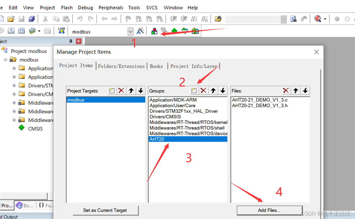
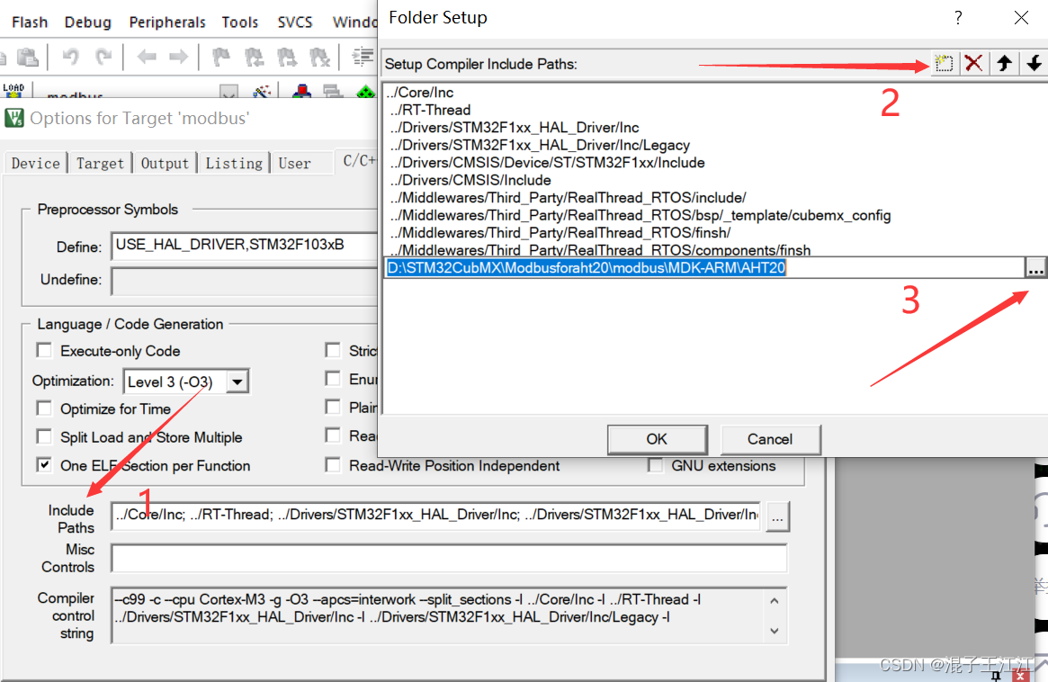
添加项目和路径:
2、移植freeModebusRTU
下载链接:freeModebusRTU
解压过后在demo里新建一个STM32文件夹并且将BARE文件夹里的文件以及modbus文件夹全部复制到刚刚建立的STM32MB文件夹里:
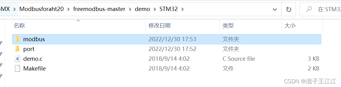
将STM32放在项目里的MDK-ARM文件
添加文件及路径
MB内添加STM32MB文件夹下modbus文件夹内所有文件,MB_Port内添加STM32MB文件夹下port文件夹内所有.c文件以及根目录的demo.c文件
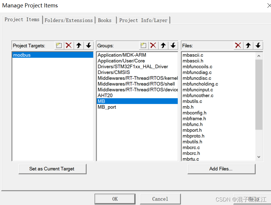


到这里移植步骤完成。
3、代码配置
demo.c:
/* ----------------------- Modbus includes ----------------------------------*/
#include "mb.h"
#include "mbport.h"
#include "AHT20-21_DEMO_V1_3.h"

/* ----------------------- Defines ------------------------------------------*/
#define REG_INPUT_START 0
#define REG_INPUT_NREGS 5

/* ----------------------- Static variables ---------------------------------*/
static USHORT   usRegInputStart = REG_INPUT_START;
//static
uint16_t   usRegInputBuf[REG_INPUT_NREGS];
uint16_t InputBuff[5];
uint32_t CT_data[2]={

    0,0};
	volatile int  c1,c2,t1,t2;

eMBErrorCode
eMBRegInputCB( UCHAR * pucRegBuffer, USHORT usAddress, USHORT usNRegs )
{


    eMBErrorCode    eStatus = MB_ENOERR;
    int             iRegIndex;
		int             i;
		AHT20_Read_CTdata_crc(CT_data);  //crc校验后,读取AHT20的温度和湿度数据
		c1 = CT_data[0]*1000/1024/1024;  //计算得到湿度值c1(放大了10倍)
		t1 = CT_data[1]*2000/1024/1024-500;//计算得到温度值t1(放大了10倍)
		c2 = c1/10 + (c1/10)%10;
		t2 = t1/10 + (t1/10)%10;
		InputBuff[0] = t2;
		InputBuff[1] = c2;
		InputBuff[2] = 0x01;
		InputBuff[3] = 0x01;

    if( ( usAddress >= REG_INPUT_START )
        && ( usAddress + usNRegs <= REG_INPUT_START + REG_INPUT_NREGS ) )
    {


        iRegIndex = ( int )( usAddress - usRegInputStart );
				for(i=0;i<usNRegs;i++)
				{


					*pucRegBuffer=InputBuff[i+usAddress-1]>>8;
					pucRegBuffer++;
					*pucRegBuffer=InputBuff[i+usAddress-1]&0xff;
					pucRegBuffer++;
				}
    }
    else
    {


        eStatus = MB_ENOREG;
    }

    return eStatus;
}

eMBErrorCode
eMBRegHoldingCB( UCHAR * pucRegBuffer, USHORT usAddress, USHORT usNRegs,
                 eMBRegisterMode eMode )
{


    return MB_ENOREG;
}


eMBErrorCode
eMBRegCoilsCB( UCHAR * pucRegBuffer, USHORT usAddress, USHORT usNCoils,
               eMBRegisterMode eMode )
{


    return MB_ENOREG;
}

eMBErrorCode
eMBRegDiscreteCB( UCHAR * pucRegBuffer, USHORT usAddress, USHORT usNDiscrete )
{


    return MB_ENOREG;
}
stm32f1xx_it.c:
/* USER CODE BEGIN Header */
/**
  ******************************************************************************
  * @file    stm32f1xx_it.c
  * @brief   Interrupt Service Routines.
  ******************************************************************************
  * @attention
  *
  * Copyright (c) 2022 STMicroelectronics.
  * All rights reserved.
  *
  * This software is licensed under terms that can be found in the LICENSE file
  * in the root directory of this software component.
  * If no LICENSE file comes with this software, it is provided AS-IS.
  *
  ******************************************************************************
  */
/* USER CODE END Header */

/* Includes ------------------------------------------------------------------*/
#include "main.h"
#include "stm32f1xx_it.h"
/* Private includes ----------------------------------------------------------*/
/* USER CODE BEGIN Includes */
/* USER CODE END Includes */

/* Private typedef -----------------------------------------------------------*/
/* USER CODE BEGIN TD */

/* USER CODE END TD */

/* Private define ------------------------------------------------------------*/
/* USER CODE BEGIN PD */

/* USER CODE END PD */

/* Private macro -------------------------------------------------------------*/
/* USER CODE BEGIN PM */

/* USER CODE END PM */

/* Private variables ---------------------------------------------------------*/
/* USER CODE BEGIN PV */

/* USER CODE END PV */

/* Private function prototypes -----------------------------------------------*/
/* USER CODE BEGIN PFP */
extern void prvvUARTTxReadyISR(void);
extern void prvvUARTRxISR(void);
extern void prvvTIMERExpiredISR( void );

/* USER CODE END PFP */

/* Private user code ---------------------------------------------------------*/
/* USER CODE BEGIN 0 */

/* USER CODE END 0 */

/* External variables --------------------------------------------------------*/
extern DMA_HandleTypeDef hdma_i2c1_rx;
extern DMA_HandleTypeDef hdma_i2c1_tx;
extern I2C_HandleTypeDef hi2c1;
extern TIM_HandleTypeDef htim3;
extern UART_HandleTypeDef huart1;
/* USER CODE BEGIN EV */

/* USER CODE END EV */

/******************************************************************************/
/*           Cortex-M3 Processor Interruption and Exception Handlers          */
/******************************************************************************/
/**
  * @brief This function handles Non maskable interrupt.
  */
void NMI_Handler(void)
{


  /* USER CODE BEGIN NonMaskableInt_IRQn 0 */

  /* USER CODE END NonMaskableInt_IRQn 0 */
  /* USER CODE BEGIN NonMaskableInt_IRQn 1 */
  while (1)
  {


  }
  /* USER CODE END NonMaskableInt_IRQn 1 */
}

/**
  * @brief This function handles Memory management fault.
  */
void MemManage_Handler(void)
{


  /* USER CODE BEGIN MemoryManagement_IRQn 0 */

  /* USER CODE END MemoryManagement_IRQn 0 */
  while (1)
  {


    /* USER CODE BEGIN W1_MemoryManagement_IRQn 0 */
    /* USER CODE END W1_MemoryManagement_IRQn 0 */
  }
}

/**
  * @brief This function handles Prefetch fault, memory access fault.
  */
void BusFault_Handler(void)
{


  /* USER CODE BEGIN BusFault_IRQn 0 */

  /* USER CODE END BusFault_IRQn 0 */
  while (1)
  {


    /* USER CODE BEGIN W1_BusFault_IRQn 0 */
    /* USER CODE END W1_BusFault_IRQn 0 */
  }
}

/**
  * @brief This function handles Undefined instruction or illegal state.
  */
void UsageFault_Handler(void)
{


  /* USER CODE BEGIN UsageFault_IRQn 0 */

  /* USER CODE END UsageFault_IRQn 0 */
  while (1)
  {


    /* USER CODE BEGIN W1_UsageFault_IRQn 0 */
    /* USER CODE END W1_UsageFault_IRQn 0 */
  }
}

/**
  * @brief This function handles Debug monitor.
  */
void DebugMon_Handler(void)
{


  /* USER CODE BEGIN DebugMonitor_IRQn 0 */

  /* USER CODE END DebugMonitor_IRQn 0 */
  /* USER CODE BEGIN DebugMonitor_IRQn 1 */

  /* USER CODE END DebugMonitor_IRQn 1 */
}

/******************************************************************************/
/* STM32F1xx Peripheral Interrupt Handlers                                    */
/* Add here the Interrupt Handlers for the used peripherals.                  */
/* For the available peripheral interrupt handler names,                      */
/* please refer to the startup file (startup_stm32f1xx.s).                    */
/******************************************************************************/

/**
  * @brief This function handles DMA1 channel6 global interrupt.
  */
void DMA1_Channel6_IRQHandler(void)
{


  /* USER CODE BEGIN DMA1_Channel6_IRQn 0 */

  /* USER CODE END DMA1_Channel6_IRQn 0 */
  HAL_DMA_IRQHandler(&hdma_i2c1_tx);
  /* USER CODE BEGIN DMA1_Channel6_IRQn 1 */

  /* USER CODE END DMA1_Channel6_IRQn 1 */
}

/**
  * @brief This function handles DMA1 channel7 global interrupt.
  */
void DMA1_Channel7_IRQHandler(void)
{


  /* USER CODE BEGIN DMA1_Channel7_IRQn 0 */

  /* USER CODE END DMA1_Channel7_IRQn 0 */
  HAL_DMA_IRQHandler(&hdma_i2c1_rx);
  /* USER CODE BEGIN DMA1_Channel7_IRQn 1 */

  /* USER CODE END DMA1_Channel7_IRQn 1 */
}

/**
  * @brief This function handles TIM3 global interrupt.
  */
void TIM3_IRQHandler(void)
{


  /* USER CODE BEGIN TIM3_IRQn 0 */

  /* USER CODE END TIM3_IRQn 0 */
  HAL_TIM_IRQHandler(&htim3);
  /* USER CODE BEGIN TIM3_IRQn 1 */

  /* USER CODE END TIM3_IRQn 1 */
}

/**
  * @brief This function handles I2C1 event interrupt.
  */
void I2C1_EV_IRQHandler(void)
{


  /* USER CODE BEGIN I2C1_EV_IRQn 0 */

  /* USER CODE END I2C1_EV_IRQn 0 */
  HAL_I2C_EV_IRQHandler(&hi2c1);
  /* USER CODE BEGIN I2C1_EV_IRQn 1 */

  /* USER CODE END I2C1_EV_IRQn 1 */
}

/**
  * @brief This function handles USART1 global interrupt.
  */
void USART1_IRQHandler(void)
{


  /* USER CODE BEGIN USART1_IRQn 0 */

  /* USER CODE END USART1_IRQn 0 */
  HAL_UART_IRQHandler(&huart1);
  /* USER CODE BEGIN USART1_IRQn 1 */
	if(__HAL_UART_GET_IT_SOURCE(&huart1, UART_IT_RXNE)!= RESET)
		{


			prvvUARTRxISR();//接收中断
		}

	if(__HAL_UART_GET_IT_SOURCE(&huart1, UART_IT_TXE)!= RESET)
		{


			prvvUARTTxReadyISR();//发送中断
		}

  HAL_NVIC_ClearPendingIRQ(USART1_IRQn);
  HAL_UART_IRQHandler(&huart1);
  /* USER CODE END USART1_IRQn 1 */
}

/* USER CODE BEGIN 1 */
void HAL_TIM_PeriodElapsedCallback(TIM_HandleTypeDef *htim)	//定时器中断回调函数,用于连接porttimer.c文件的函数
{


  /* NOTE : This function Should not be modified, when the callback is needed,
            the __HAL_TIM_PeriodElapsedCallback could be implemented in the user file
   */
  	prvvTIMERExpiredISR( );
}
/* USER CODE END 1 */
port.h:
/*
 * FreeModbus Libary: BARE Port
 * Copyright (C) 2006 Christian Walter <[email protected]>
 *
 * This library is free software; you can redistribute it and/or
 * modify it under the terms of the GNU Lesser General Public
 * License as published by the Free Software Foundation; either
 * version 2.1 of the License, or (at your option) any later version.
 *
 * This library is distributed in the hope that it will be useful,
 * but WITHOUT ANY WARRANTY; without even the implied warranty of
 * MERCHANTABILITY or FITNESS FOR A PARTICULAR PURPOSE.  See the GNU
 * Lesser General Public License for more details.
 *
 * You should have received a copy of the GNU Lesser General Public
 * License along with this library; if not, write to the Free Software
 * Foundation, Inc., 51 Franklin St, Fifth Floor, Boston, MA  02110-1301  USA
 *
 * File: $Id$
 */

#ifndef _PORT_H
#define _PORT_H

#include <assert.h>
#include <inttypes.h>
#include "stm32f1xx_hal.h"

#define	INLINE                      inline
#define PR_BEGIN_EXTERN_C           extern "C" {


#define	PR_END_EXTERN_C             }

#define ENTER_CRITICAL_SECTION( )   __set_PRIMASK(1) 	 //关总中断
#define EXIT_CRITICAL_SECTION( )    __set_PRIMASK(0)   //开总中断
typedef uint8_t BOOL;

typedef unsigned char UCHAR;
typedef char CHAR;

typedef uint16_t USHORT;
typedef int16_t SHORT;

typedef uint32_t ULONG;
typedef int32_t LONG;

#ifndef TRUE
#define TRUE            1
#endif

#ifndef FALSE
#define FALSE           0
#endif

#endif
portserial.c:
/*
 * FreeModbus Libary: BARE Port
 * Copyright (C) 2006 Christian Walter <[email protected]>
 *
 * This library is free software; you can redistribute it and/or
 * modify it under the terms of the GNU Lesser General Public
 * License as published by the Free Software Foundation; either
 * version 2.1 of the License, or (at your option) any later version.
 *
 * This library is distributed in the hope that it will be useful,
 * but WITHOUT ANY WARRANTY; without even the implied warranty of
 * MERCHANTABILITY or FITNESS FOR A PARTICULAR PURPOSE.  See the GNU
 * Lesser General Public License for more details.
 *
 * You should have received a copy of the GNU Lesser General Public
 * License along with this library; if not, write to the Free Software
 * Foundation, Inc., 51 Franklin St, Fifth Floor, Boston, MA  02110-1301  USA
 *
 * File: $Id$
 */

#include "port.h"

/* ----------------------- Modbus includes ----------------------------------*/
#include "mb.h"
#include "mbport.h"
#include "usart.h"

/* ----------------------- static functions ---------------------------------*/
void prvvUARTTxReadyISR( void );
void prvvUARTRxISR( void );

/* ----------------------- Start implementation -----------------------------*/
void
vMBPortSerialEnable( BOOL xRxEnable, BOOL xTxEnable )
{


    /* If xRXEnable enable serial receive interrupts. If xTxENable enable
     * transmitter empty interrupts.
     */
	 if (xRxEnable)															//将串口收发中断和modbus联系起来,下面的串口改为自己使能的串口
			{


				__HAL_UART_ENABLE_IT(&huart1,UART_IT_RXNE);	//我用的是串口1,故为&huart1
			}
		else
			{


				__HAL_UART_DISABLE_IT(&huart1,UART_IT_RXNE);
			}
		if (xTxEnable)
			{


				__HAL_UART_ENABLE_IT(&huart1,UART_IT_TXE);
			}
		else
			{


				__HAL_UART_DISABLE_IT(&huart1,UART_IT_TXE);
			}
}

BOOL
xMBPortSerialInit( UCHAR ucPORT, ULONG ulBaudRate, UCHAR ucDataBits, eMBParity eParity )
{


    return TRUE;
}

BOOL
xMBPortSerialPutByte( CHAR ucByte )
{


    /* Put a byte in the UARTs transmit buffer. This function is called
     * by the protocol stack if pxMBFrameCBTransmitterEmpty( ) has been
     * called. */
	if(HAL_UART_Transmit (&huart1 ,(uint8_t *)&ucByte,1,0x01) != HAL_OK )	//添加发送一位代码
			   return FALSE ;
			else
    return TRUE;
}

BOOL
xMBPortSerialGetByte( CHAR * pucByte )
{


    /* Return the byte in the UARTs receive buffer. This function is called
     * by the protocol stack after pxMBFrameCBByteReceived( ) has been called.
     */
	if(HAL_UART_Receive (&huart1 ,(uint8_t *)pucByte,1,0x01) != HAL_OK )//添加接收一位代码
			    return FALSE ;
	   else
    return TRUE;
}

/* Create an interrupt handler for the transmit buffer empty interrupt
 * (or an equivalent) for your target processor. This function should then
 * call pxMBFrameCBTransmitterEmpty( ) which tells the protocol stack that
 * a new character can be sent. The protocol stack will then call
 * xMBPortSerialPutByte( ) to send the character.
 */
void prvvUARTTxReadyISR( void )
{


    pxMBFrameCBTransmitterEmpty(  );
}

/* Create an interrupt handler for the receive interrupt for your target
 * processor. This function should then call pxMBFrameCBByteReceived( ). The
 * protocol stack will then call xMBPortSerialGetByte( ) to retrieve the
 * character.
 */
void prvvUARTRxISR( void )
{


    pxMBFrameCBByteReceived(  );
}
porttimer.c:
/*
 * FreeModbus Libary: BARE Port
 * Copyright (C) 2006 Christian Walter <[email protected]>
 *
 * This library is free software; you can redistribute it and/or
 * modify it under the terms of the GNU Lesser General Public
 * License as published by the Free Software Foundation; either
 * version 2.1 of the License, or (at your option) any later version.
 *
 * This library is distributed in the hope that it will be useful,
 * but WITHOUT ANY WARRANTY; without even the implied warranty of
 * MERCHANTABILITY or FITNESS FOR A PARTICULAR PURPOSE.  See the GNU
 * Lesser General Public License for more details.
 *
 * You should have received a copy of the GNU Lesser General Public
 * License along with this library; if not, write to the Free Software
 * Foundation, Inc., 51 Franklin St, Fifth Floor, Boston, MA  02110-1301  USA
 *
 * File: $Id$
 */

/* ----------------------- Platform includes --------------------------------*/
#include "port.h"
#include "stm32f1xx_hal.h"
#include "tim.h"
/* ----------------------- Modbus includes ----------------------------------*/
#include "mb.h"
#include "mbport.h"

/* ----------------------- static functions ---------------------------------*/
void prvvTIMERExpiredISR( void );

/* ----------------------- Start implementation -----------------------------*/
BOOL
xMBPortTimersInit( USHORT usTim1Timerout50us )//定时器初始化直接返回TRUE,已经在mian函数初始化过
{


    return  TRUE;
}


inline void
vMBPortTimersEnable(  )//使能定时器中断,我用的是定时器4,所以为&htim4
{


    /* Enable the timer with the timeout passed to xMBPortTimersInit( ) */
				 /* Enable the timer with the timeout passed to xMBPortTimersInit( ) */
		__HAL_TIM_CLEAR_IT(&htim3,TIM_IT_UPDATE);
		__HAL_TIM_ENABLE_IT(&htim3,TIM_IT_UPDATE);
		__HAL_TIM_SET_COUNTER(&htim3,0);
		__HAL_TIM_ENABLE(&htim3);
}

inline void
vMBPortTimersDisable(  )//取消定时器中断
{


    /* Disable any pending timers. */
	__HAL_TIM_DISABLE(&htim3);
			__HAL_TIM_SET_COUNTER(&htim3,0);
			__HAL_TIM_DISABLE_IT(&htim3,TIM_IT_UPDATE);
			__HAL_TIM_CLEAR_IT(&htim3,TIM_IT_UPDATE);

}

/* Create an ISR which is called whenever the timer has expired. This function
 * must then call pxMBPortCBTimerExpired( ) to notify the protocol stack that
 * the timer has expired.
 */
void prvvTIMERExpiredISR( void )//modbus定时器动作,需要在中断内使用
{


    ( void )pxMBPortCBTimerExpired(  );
}
创建多任务:
Application/USER文件夹下新建app_rt_thread.c,并填入下面代码:
#include "rtthread.h"
#include "main.h"
#include "stdio.h"
#include "usart.h"
#include "AHT20-21_DEMO_V1_3.h"
#include "mb.h"
#include "mbport.h"

struct rt_thread led1_thread;
rt_uint8_t rt_led1_thread_stack[128];
void led1_task_entry(void *parameter);


//初始化线程函数
void MX_RT_Thread_Init(void)
{


	//初始化LED1线程
	rt_thread_init(&led1_thread,"led1",led1_task_entry,RT_NULL,&rt_led1_thread_stack[0],sizeof(rt_led1_thread_stack),3,20);
	//开启线程调度
	rt_thread_startup(&led1_thread);
}

//主任务
void MX_RT_Thread_Process(void)
{


	( void )eMBPoll(  );//启动modbus侦听

}

//LED1任务
void led1_task_entry(void *parameter)
{


	while(1)
	{


		HAL_GPIO_WritePin(GPIOB,GPIO_PIN_15, GPIO_PIN_RESET);
		rt_thread_delay(500);
		HAL_GPIO_WritePin(GPIOB,GPIO_PIN_15, GPIO_PIN_SET);
		rt_thread_delay(500);
	}
}
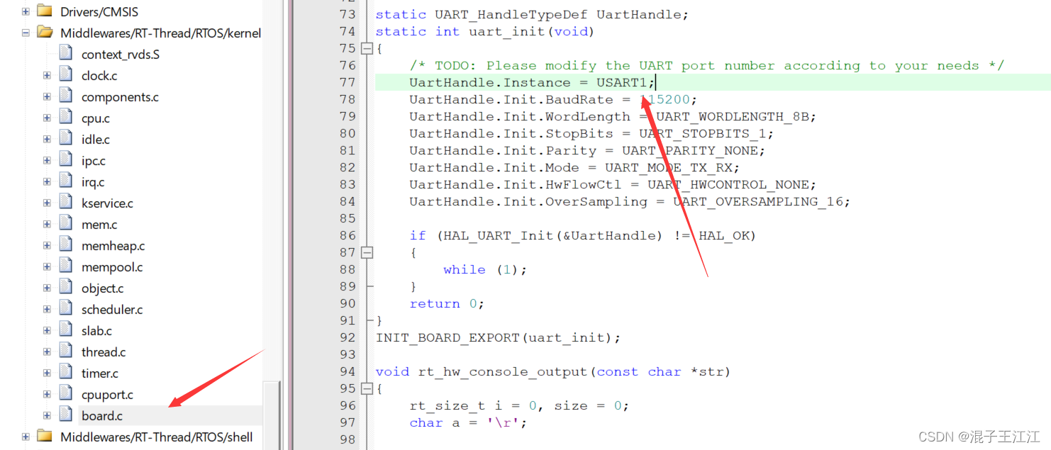
修改board.c文件下的串口为USART2为USART1:
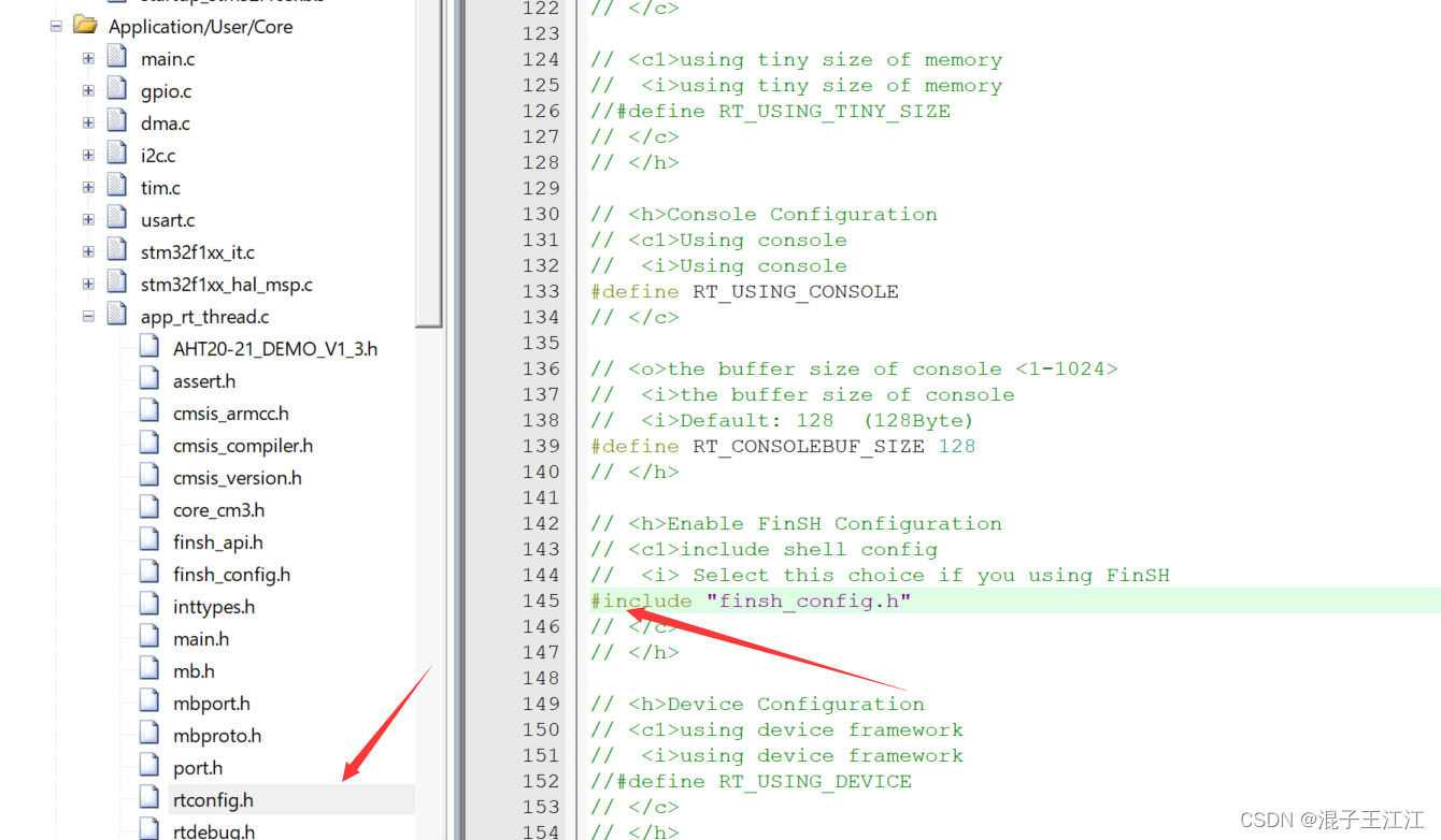
将app_rt_thread.c下的rtconfig.h下的这句注释去掉:
main.c:
/* USER CODE BEGIN Header */
/**
  ******************************************************************************
  * @file           : main.c
  * @brief          : Main program body
  ******************************************************************************
  * @attention
  *
  * Copyright (c) 2022 STMicroelectronics.
  * All rights reserved.
  *
  * This software is licensed under terms that can be found in the LICENSE file
  * in the root directory of this software component.
  * If no LICENSE file comes with this software, it is provided AS-IS.
  *
  ******************************************************************************
  */
/* USER CODE END Header */
/* Includes ------------------------------------------------------------------*/
#include "main.h"
#include "dma.h"
#include "i2c.h"
#include "tim.h"
#include "usart.h"
#include "gpio.h"
#include "mb.h"
#include "mbport.h"
/* Private includes ----------------------------------------------------------*/
/* USER CODE BEGIN Includes */
#include <stdio.h>
#include "AHT20-21_DEMO_V1_3.h"
/* USER CODE END Includes */

/* Private typedef -----------------------------------------------------------*/
/* USER CODE BEGIN PTD */
extern void MX_RT_Thread_Init(void);
extern void MX_RT_Thread_Process(void);
/* USER CODE END PTD */

/* Private define ------------------------------------------------------------*/
/* USER CODE BEGIN PD */
/* USER CODE END PD */

/* Private macro -------------------------------------------------------------*/
/* USER CODE BEGIN PM */

/* USER CODE END PM */

/* Private variables ---------------------------------------------------------*/

/* USER CODE BEGIN PV */

/* USER CODE END PV */

/* Private function prototypes -----------------------------------------------*/
void SystemClock_Config(void);
/* USER CODE BEGIN PFP */

/* USER CODE END PFP */

/* Private user code ---------------------------------------------------------*/
/* USER CODE BEGIN 0 */

/* USER CODE END 0 */

/**
  * @brief  The application entry point.
  * @retval int
  */
int main(void)
{


  /* USER CODE BEGIN 1 */
  /* USER CODE END 1 */

  /* MCU Configuration--------------------------------------------------------*/

  /* Reset of all peripherals, Initializes the Flash interface and the Systick. */
  HAL_Init();

  /* USER CODE BEGIN Init */

  /* USER CODE END Init */

  /* Configure the system clock */
  SystemClock_Config();

  /* USER CODE BEGIN SysInit */

  /* USER CODE END SysInit */

  /* Initialize all configured peripherals */
  MX_GPIO_Init();
  MX_DMA_Init();
  MX_I2C1_Init();
  MX_USART1_UART_Init();
  MX_TIM3_Init();
	AHT20_Init();
	eMBInit( MB_RTU, 0x01, 1, 115200, MB_PAR_NONE);//初始化modbus,走modbusRTU,从站地址为0x01,端口为1。
	eMBEnable(  );//使能modbus
  /* USER CODE BEGIN 2 */
 MX_RT_Thread_Init();

  /* USER CODE END 2 */

  /* Infinite loop */
  /* USER CODE BEGIN WHILE */
  while (1)
  {


    /* USER CODE END WHILE */
		( void )eMBPoll(  );//启动modbus侦听
    /* USER CODE BEGIN 3 */
  }
  /* USER CODE END 3 */
}

/**
  * @brief System Clock Configuration
  * @retval None
  */
void SystemClock_Config(void)
{


  RCC_OscInitTypeDef RCC_OscInitStruct = {

    0};
  RCC_ClkInitTypeDef RCC_ClkInitStruct = {

    0};

  /** Initializes the RCC Oscillators according to the specified parameters
  * in the RCC_OscInitTypeDef structure.
  */
  RCC_OscInitStruct.OscillatorType = RCC_OSCILLATORTYPE_HSE;
  RCC_OscInitStruct.HSEState = RCC_HSE_ON;
  RCC_OscInitStruct.HSEPredivValue = RCC_HSE_PREDIV_DIV1;
  RCC_OscInitStruct.HSIState = RCC_HSI_ON;
  RCC_OscInitStruct.PLL.PLLState = RCC_PLL_ON;
  RCC_OscInitStruct.PLL.PLLSource = RCC_PLLSOURCE_HSE;
  RCC_OscInitStruct.PLL.PLLMUL = RCC_PLL_MUL9;
  if (HAL_RCC_OscConfig(&RCC_OscInitStruct) != HAL_OK)
  {


    Error_Handler();
  }

  /** Initializes the CPU, AHB and APB buses clocks
  */
  RCC_ClkInitStruct.ClockType = RCC_CLOCKTYPE_HCLK|RCC_CLOCKTYPE_SYSCLK
                              |RCC_CLOCKTYPE_PCLK1|RCC_CLOCKTYPE_PCLK2;
  RCC_ClkInitStruct.SYSCLKSource = RCC_SYSCLKSOURCE_PLLCLK;
  RCC_ClkInitStruct.AHBCLKDivider = RCC_SYSCLK_DIV1;
  RCC_ClkInitStruct.APB1CLKDivider = RCC_HCLK_DIV2;
  RCC_ClkInitStruct.APB2CLKDivider = RCC_HCLK_DIV1;

  if (HAL_RCC_ClockConfig(&RCC_ClkInitStruct, FLASH_LATENCY_2) != HAL_OK)
  {


    Error_Handler();
  }
}

/* USER CODE BEGIN 4 */

/* USER CODE END 4 */

/**
  * @brief  This function is executed in case of error occurrence.
  * @retval None
  */
void Error_Handler(void)
{


  /* USER CODE BEGIN Error_Handler_Debug */
  /* User can add his own implementation to report the HAL error return state */
  __disable_irq();
  while (1)
  {


  }
  /* USER CODE END Error_Handler_Debug */
}

#ifdef  USE_FULL_ASSERT
/**
  * @brief  Reports the name of the source file and the source line number
  *         where the assert_param error has occurred.
  * @param  file: pointer to the source file name
  * @param  line: assert_param error line source number
  * @retval None
  */
void assert_failed(uint8_t *file, uint32_t line)
{


  /* USER CODE BEGIN 6 */
  /* User can add his own implementation to report the file name and line number,
     ex: printf("Wrong parameters value: file %s on line %d\r\n", file, line) */
  /* USER CODE END 6 */
}
#endif /* USE_FULL_ASSERT */
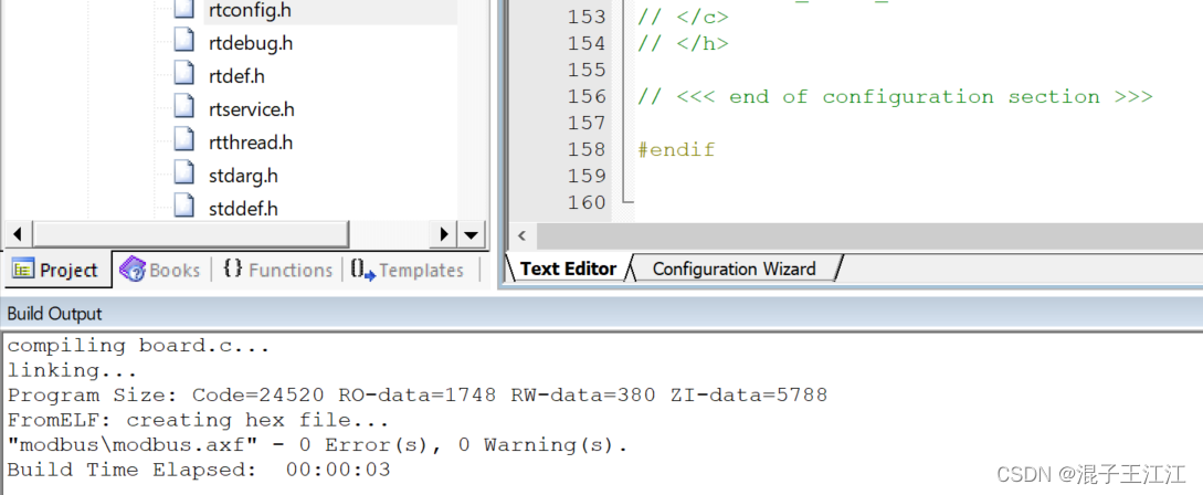
编译通过:
四、总结
移植步骤繁多,需要小心配置,我就是有一个地方的代码放错了,导致一直在寻找错误,浪费了大量的时间。再有就是传感器到了,本想着可以显示了,结果板子出问题了,一直烧不进去,就很无语!
五、参考资料
https://blog.csdn.net/weixin_46129506/article/details/121914039
https://blog.csdn.net/weixin_56102526/article/details/121952050
https://blog.csdn.net/qq_47281915/article/details/122328414