文章目录
一、知识储备
为什么要进行tb文件测试?
编写testbench的目的就是为了测试使用HDL设计的电路,对其进行仿真验证、测试设计电路的功能、性能与设计的 预期是否相符。
大体的步骤:
产生激励
将产生的激励加入到被测试模块中并观察其响应;
将输出响应与期望值比较。
1、tb文件的基本结构
设定仿真时间单位/精度
module project_tb ( );


	逻辑设计中输入信号在这里对应reg型变量
	逻辑设计中的输出信号在这里对应wire型

	待测试模块的例化 //例如例化一个与门
	//括号里面不一定就是ab,主要根据上面的输入输出信号的定义
	 and u1 (
	     .a(a),
	     .b(b),
	     .out(out)
	 );

	使用initial或always语句块产生激励//时钟复位信号等
	//建议加$stop;因为对于quartus来说,不加则仿真会一直进行,vivado会自动根据时间停止
	监控和比较输出响应
endmodule
2、tb时钟激励的产生
产生占空比为50%的时钟脉冲
//产生时钟激励
initial clk = 1'b0;
always #5 clk = ~clk; //时钟周期为10
产生固定数量的时钟脉冲
//产生10次每5ns进行翻转的clk信号
`timescale 1ns/1ps
`define clock_period 10

module test ( );
    //输入对应reg型
    reg clk;
    //被测试模块例化
    dut u1(
        .clk(clk)
    );
    //产生时钟激励
    initial begin
	     clk = 1'b0;
		  repeat(10)
		  #(`clock_period/2) clk = ~clk;

	 end
endmodule
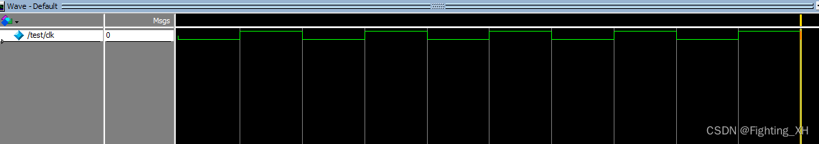
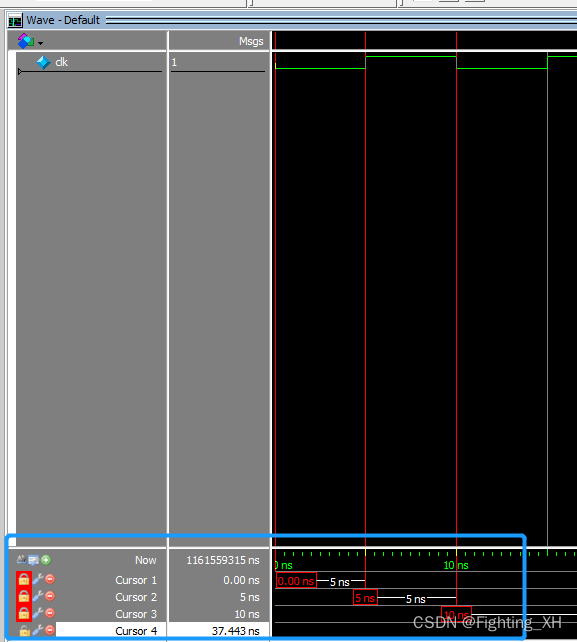
波形如下:
3、tb复位激励的产生
initial begin
    reset = 1'b1;
    #10;
    reset = 1'b0;
end
4、tb 输入激励的产生
initial begin
    A = 1'b0 ;
    #10;
    A = 1'b1 ;
    #10;
    A = 1'b0 ;
end
5、仿真终端显示描述
$monitor    //仿真打印输出,打印出仿真过程中的变量,使其终端显示
  //比如:    $monitor($time,"clk = %d reset = %d out = %d",clk,reset,out);
$display   //终端打印字符串,显示仿真结果等
 //比如:     $display("Simulation start !");
             $display("input is %b %b %b,output is %b",a,b,en,z);
$time      //返回64位整型时间
$stime     //返回32位整型时间
$realtiime //实行实型模拟时间
例如:
`timescale 1ps/1ps
module test();
reg [1:0] in;
wire out;
andgate u1(
.in(in),
.out(out)
);
initial begin
in = 2'b00;
#10;
in = 2'b01;
#10;
in = 2'b10;
#10;
in = 2'b11;
#10;
//终端打印字符串,显示仿真结果等
$monitor($time);
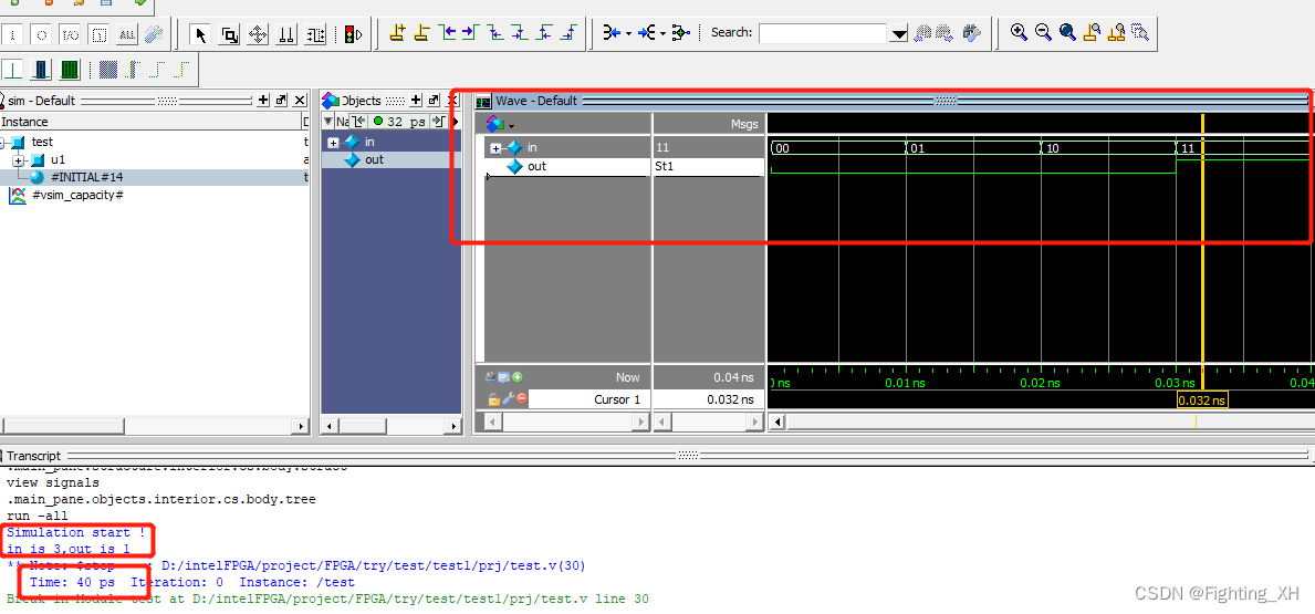
$display("Simulation start !");
$display("in is %d,out is %d",in,out);
$stop;
end
endmodule
Modelsim界面如下,不仅有波形,还能显示时间
6、tb文件中的主要函数语法
$stop        //停止运行仿真,常用
$stop(n)     //带参数系统任务,根据参数0,1,或2不同,输出仿真信息
$finish      //结束运行仿真,不可继续仿真
$finish(n)   //带参数系统任务,根据参数的不同:0,1或2,输出仿真信息
                 // 0: 不输出任何信息
                // 1: 输出当前仿真时刻和位置
               // 2:输出房前仿真时刻、位置和仿真过程中用到的memory以及cpu时间的统计
$random        //产生随机数
$random%n     //产生范围-n到n之间的随机数
{

    $random}%n    //产生范围0到n之间的随机数
如下,我们仍然实现上面的与门仿真,但是这次我们随机产生in的值。
使用HDLbits提供的仿真进行测试,点击进入
module top_module ();
	reg clk=0;
	always #5 clk = ~clk;  // Create clock with period=10
    `probe(clk);
	initial `probe_start;   // Start the timing diagram

	// A testbench
    reg [1:0] in=2'b0;
    integer i = 89;
    integer j = 9;

    //产生随机输入激励
	initial begin
        #10;
        in = $random(j);
        #10;
        in = {

    $random(i)}%3; //产生0-3 之间的值
        #10;
        in = $random(j);
        #10;
		in = $random(i);
        #10;
		in = $random(i);
        #10;
		in = $random(i);
		$display ("Hello world! The current time is (%0d ps)", $time);
		#50 $finish;            // Quit the simulation
	end

//模块例化
	    andgate u1(
        .in(in),
        .out(out)
    );

    `probe(in);	// Sub-modules can also have `probe()
    `probe(out);
endmodule
//待测试模块的功能
module andgate(input [1:0]  in, output out);
 assign out = in[0] &  in[1];
endmodule
波形如下:
二、HDLbits题目部分
1、Tb/clock 产生时钟激励
提供如果模块:
module dut ( input clk ) ;
编写一个测试平台,创建一个模块 dut 实例(具有任何实例名称),并创建一个时钟信号来驱动模块的 clk 输入。时钟的周期为 10 ps。时钟应初始化为零,其第一个转换为 0 到 1。
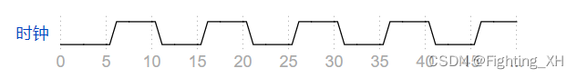
首先时钟周期是10ps,波形也可以看出是每5ps clk翻转一次
`timescale 1ps/1ps
module top_module ( );
    //输入对应reg型
    reg clk;
    //被测试模块例化
    dut u1(
        .clk(clk)
    );
    //产生时钟激励
    initial clk = 1'b0;
    always #5 clk = ~clk;

endmodule
在题目的基础上,我们将时钟周期变成10ns,代码如下:
仍然是时钟周期10ns,因此5ns的时候进行clk的翻转
`timescale 1ns/1ps
module test ( );
    //输入对应reg型
    reg clk;
    //被测试模块例化
    dut u1(
        .clk(clk)
    );
    //产生时钟激励
    initial clk = 1'b0;
    always #5 clk = ~clk;

endmodule
波形如下,也可以看出是每5ns clk翻转一次,整个的时钟周期是10ns
2、Tb1 有输出
创建一个 Verilog 测试平台,该测试平台将为输出 A 和 B 生成以下波形:
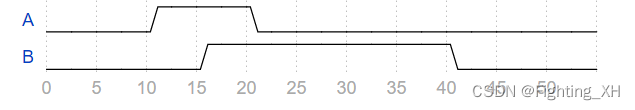
该题直接对着波形图给AB激励就可以,主要点在于AB所对应的时间。
方法一:AB分别写initial块
module top_module ( output reg A, output reg B );

    initial begin
        A = 1'b0 ;
        #10;
        A = 1'b1 ;
        #10;
        A = 1'b0 ;
    end

    initial begin
        B = 1'b0 ;
        #15;
        B = 1'b1 ;
        #25;
        B = 1'b0 ;
    end

endmodule
方法二:AB写到一个initial中
module top_module ( output reg A, output reg B );
    initial begin
        A = 1'b0 ;
        B = 1'b0 ;
        #10;
        A = 1'b1 ;
        #5;
        B = 1'b1 ;
        #5;
        A = 1'b0 ;
        #20;
        B = 1'b0 ;
    end
endmodule
3、Tb/and 有输入输出
给出如下与门模块:
module andgate (
    input [1:0] in,
    output out
);

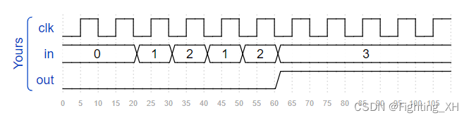
如波形所示,编写激励,来测试四个输入组合。根据波形来看输入in的四种取值,以及延迟的时间。
module top_module();

    reg [1:0] in;
    wire out;

    andgate u1(
        .in(in),
        .out(out)
    );

    initial begin
        in = 2'b00;
        #10;
        in = 2'b01;
        #10;
        in = 2'b10;
        #10;
        in = 2'b11;
    end

endmodule
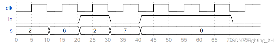
4、Tb2(含有时钟和输入输出)
有如下的波形
提供模块q7
module q7 (
    input clk,
    input in,
    input [2:0] s,
    output out
);
编写一个测试平台,实例化模块 q7 并完全按照上述波形所示生成这些输入信号。
module top_module();
    reg clk;
    reg in;
    reg [2:0] s;
    wire out;

    q7 u1(
        .clk(clk),
        .in(in),
        .s(s),
        .out(out)
    );
    //产生时钟激励
    initial
        clk = 1'b0;
    always #5 clk = ~clk;
    //产生输入激励in
    initial begin
        in = 1'b0;
        s = 3'd2;
        #10;      //10s后
        s = 3'd6;
        #10;      //20
        in = 1'b1;
        s = 3'd2;
        #10;      //30
        in = 1'b0;
        s = 3'd7;
        #10;      //40
        in = 1'b1;
        s = 3'd0;
        #30;      //70
        in = 1'b0;
    end

endmodule
5、TFF T触发器
给予T触发器模块
module tff (
    input clk,
    input reset,   // active-high synchronous reset
    input t,       // toggle
    output q
);
编写一个测试平台,该测试平台实例化一个tff,并将重置T触发器,然后将其切换到“1”状态。
题目分析
1、只需要给予三个输入激励,时钟复位激励以及输入t激励。
2、重置的时候触发器切换成1,同时T触发器有着翻转功能,因此说明重置的时候输入是0,非重置的时候输入t为1。
`timescale 1ps/1ps
module top_module ();

    reg clk;
    reg reset; //同步高电平复位
    reg t;
    wire q;

    tff u1(
        .clk(clk),
        .reset(reset),
        .t(t),
        .q(q)
    );

    initial begin
        clk = 1'b0;
        reset = 1'b1;
        t = 1'b0;
        #10;
        reset = 1'b0;
        t = 1'b1;
    end

    always #5 clk = ~clk;  //clk时钟周期10ps

endmodule
三、补充新增HDL习题
Cs450/timer计时器
实现一个计时器,该计时器在给定的时钟周期数内倒计时。
高电平复位。
计数器用10位进行加载。
输出信号tc用来指示计数器内部是否达到了0,如果是0,则为高电平。
简言之,该题就是设计一个递减计数器,同时当计数到0的时候,则拉高输出tc信号。

module top_module(
	input clk,
	input load,
	input [9:0] data,
	output tc
);
    reg [9:0] counter;

    always @ (posedge clk)begin
        if(load)begin
            counter <= data;
        end
        else if( counter == 0)begin
            counter <= 0;
        end
        else begin
            counter <= counter -1;
        end
    end

    assign tc = (counter)? 0: 1;
endmodule
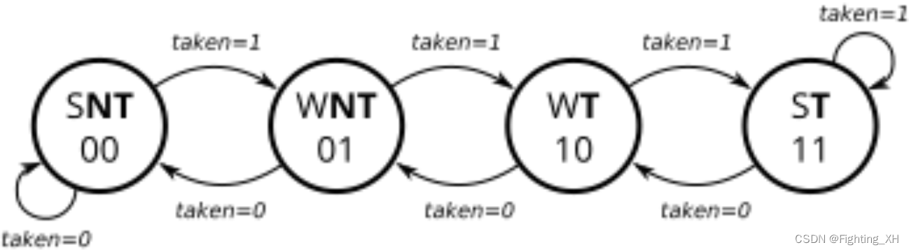
Cs450/counter 2bc
实现饱和计数器,共四个状态,判断条件为taken,高电平为递增计数器,低电平为递减计数器。当不train的时候(train_valid = 0),计数器的值保持不变
最多计数 3(或 2’b11)或向下计数为 0(或 2’b00),但不环绕。
复位为异步复位,将计数器复位为01状态。
module top_module(
    input clk,
    input areset,
    input train_valid,
    input train_taken,
    output reg [1:0] state
);
    always @(posedge clk, posedge areset) begin
        if (areset)
            state <= 2'b01;
        else if (train_valid) begin
            if (train_taken)
                state <= (state == 2'b11) ? 2'b11 : (state + 1'b1); //递增计数器,计数到最大值保持,否则递增计数
            else
                state <= (state == 2'b00) ? 2'b00 : (state - 1'b1); //递减计数器,计数到最小值保持,否则递减计数
        end
        else
            state <= state;
    end
endmodule
Cs450/history shift 历史移位寄存器
历史移位寄存器用来记录历史数据。该寄存器被的数据保存下来以供以后用于分支预测器训练和管道刷新。
如果同时发生预测和错误预测,则错误预测优先。
当预测 = 1 时,从 LSB 端移入以更新预测的历史记录。
当发生错误预测 = 1时,在错误预测的完成后,将历史记录寄存器与历史记录一起加载。
module top_module(
    input clk,
    input areset,

    input predict_valid,
    input predict_taken,
    output [31:0] predict_history,

    input train_mispredicted,
    input train_taken,
    input [31:0] train_history
);
    always @(posedge clk, posedge areset) begin
        if (areset)
            predict_history <= 0;
        else if (train_mispredicted)  //错误预测
            predict_history <= {

    train_history[30:0], train_taken};
        else if (predict_valid)//预测
            predict_history <= {

    predict_history[30:0], predict_taken};
    end
endmodule
Cs450/gshare
参考sdfui32iruiwed的方法来实现。