一,电机驱动芯片:L298N简介
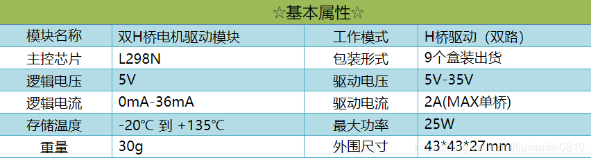
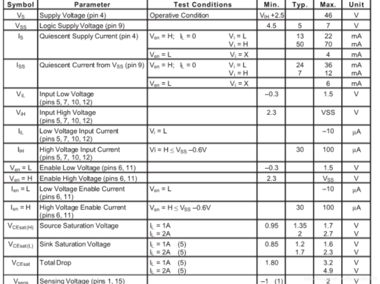
L298N 是一种双H桥电机驱动芯片,其中每个H桥可以提供2A的电流,功率部分的供电电压范围是2.5-48v,逻辑部分5v供电,接受5vTTL电平。一般情况下,功率部分的电压应大于6V否则芯片可能不能正常工作。
基本参数:
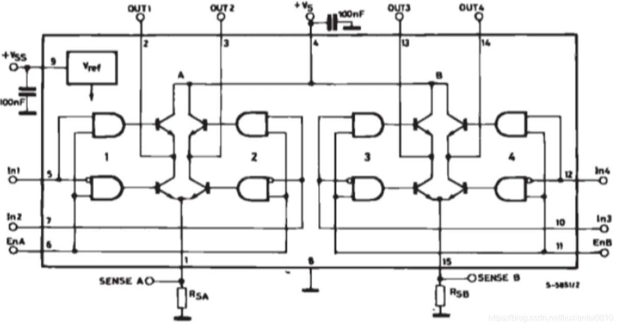
内部结构:
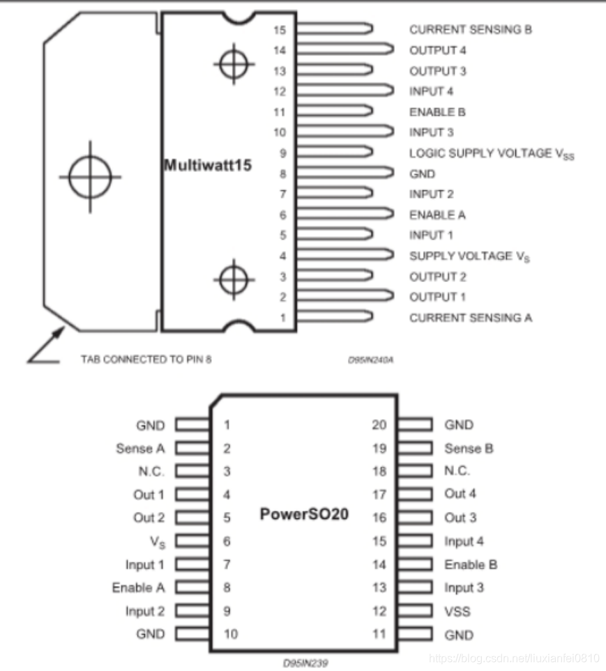
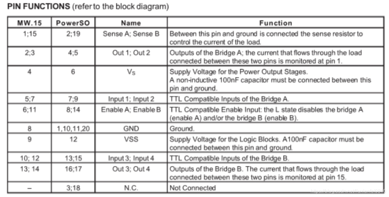
二,L298N引脚图:
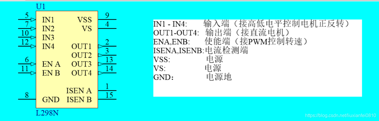
详细引脚说明如下:(摘自官方手册)
三:L98N "真值表"
ENA ENB  IN1 IN2 IN3 IN4    OUT1 OUT2 OUT3 OUT4   电机状态
0    0   X.......
0    1   X   X    0   0     X     X     0    0    停止
0    1   X   X    0   1     X     X     0    1    反转
0    1   X   X    1   0     X     X     1    0    正转
0    1   X   X    1   1     X     X     1    1    刹停
1    0  与上类似
四,测速原理:编码器
编码器(encoder)是将信号(如比特流)或数据进行编制、转换为可用以通讯、传输和存储的信号形式的设备。编码器把角位移或直线位移转换成电信号,前者称为码盘,后者称为码尺。按照读出方式编码器可以分为接触式和非接触式两种;按照工作原理编码器可分为增量式和绝对式两类。增量式编码器是将位移转换成周期性的电信号,再把这个电信号转变成计数脉冲,用脉冲的个数表示位移的大小。绝对式编码器的每一个位置对应一个确定的数字码,因此它的示值只与测量的起始和终止位置有关,而与测量的中间过程无关。
五,程序源码:
#include "reg51.h"
#define uchar unsigned char
#define uint  unsigned int
#define TH0_VALUE 0xF9
#define TL0_VALUE 0x0F
#define T1_VALUE 0XC0
#define DisplayPORTDAT  P0
#define DisplayPORTSEL  P2
#define COUNTVALUE   1000
#define	 INT0  0
#define	 TIM0  1
#define	 TIM1  3
uchar  code SegmentCode[]={0x3F, 0x06,0x5B,0x4F,0x66,0x6D,0x7D,0x07,0x7F,0x6F};
uchar  code BitCode[] =   {0X7F,0XBF,0XDF,0XEF,0XF7,0XFB,0XFD,0XFE};
sbit L298NEN=P1^0;
sbit MotorSpeedADD=P1^1;
sbit MotorSpeedMinus=P1^2;
sbit MotorForward=P1^3;
sbit MotorBackward=P1^4;
sbit MotorStop=P1^5;
sbit L298NIN1=P1^6;
sbit L298NIN2=P1^7;
typedef struct _HANDLER
{
	struct PID
	{
		float MotorSpeedSet;
		float MotorSpeedAct;
		float Kp;
		float T;
		float Ti;
		float Td;
		float Ek;
		float Kd;
		float Ki;
		float Eklast;
		float Eklastlast;
		float SEK;
		float OUT0;
		float OUT;
		uint Calc_Time;
		uint PWM;
	}pid;
	uint MotorSpeedSetDis;
	uint MotorSpeedActDis;
	uint counter;
	uint PulseIn;
	uchar disBit;
	uchar DisplayDataBuffer[8];
}Handler;
Handler handler;
void delay_ms(uint x)
{
	uint i,j;
	for(i=0;i<x;i++)
		for(j=110;j>0;j--);
}
void Func0(void)
{
	TMOD=0X21;
	TH0=TH0_VALUE;
	TL0=TL0_VALUE;
	TH1=T1_VALUE;
	TL1=T1_VALUE;
	ET1=1;
	ET0=1;
	IT0=1;
	EA=1;
	L298NIN1 = 1;
	L298NIN2 = 0;
	handler.counter=0;
	handler.PulseIn=0;
	handler.disBit=0;
	handler.DisplayDataBuffer[7]=0;
	handler.pid.Kp=18.5;
	handler.pid.MotorSpeedAct=0;
	handler.pid.MotorSpeedSet=250;
	handler.pid.Kd=1.55;
	handler.pid.Ki=13;
	handler.pid.OUT0=0;
	handler.pid.Ek=0;
	handler.pid.Eklast=0;
	handler.pid.Eklastlast=0;
	handler.pid.Calc_Time=0;
	handler.pid.PWM=100;
	//Some variables are unused
	TR0=1;
	TR1=1;
	EX0=1;
}
void Func1(void)
{
	float delEk;//Current deviation-last deviation
	float Iout;//Integral output
	float Pout;//Proportional output
	float Dout;//Differential output
	handler.pid.Ek=handler.pid.MotorSpeedSet-handler.pid.MotorSpeedAct;
	delEk=handler.pid.Ek-handler.pid.Eklast;
	Iout=handler.pid.Ki*handler.pid.Ek;
	Dout=handler.pid.Kd*(handler.pid.Ek-2*handler.pid.Eklast+handler.pid.Eklastlast);
	Pout=handler.pid.Kp*delEk;
	handler.pid.OUT=(Pout+Iout+Dout)/50+handler.pid.OUT0;
	if(handler.pid.OUT>COUNTVALUE)
	{
		handler.pid.OUT=COUNTVALUE;
	}
	else if(handler.pid.OUT<0)
	{
		handler.pid.OUT=0;
	}
	else ;
	handler.pid.Eklastlast=handler.pid.Eklast;
	handler.pid.Eklast=handler.pid.Ek;
	handler.pid.OUT0=handler.pid.OUT;
	handler.pid.PWM=(uint)handler.pid.OUT;
}
void Func2(void)
{
	if(MotorSpeedADD==0)
	{
		delay_ms(30);
		if(MotorSpeedADD==0)
		{
			handler.pid.MotorSpeedSet+=20;
			if(handler.pid.MotorSpeedSet>COUNTVALUE-300)
			{
				handler.pid.MotorSpeedSet=COUNTVALUE-300;
			}
		}
	}
	if(MotorSpeedMinus==0)
	{
		delay_ms(30);
		if(MotorSpeedMinus==0)
		{
			handler.pid.MotorSpeedSet-=20;
			if(handler.pid.MotorSpeedSet<0)
				handler.pid.MotorSpeedSet=0;
		}
	}
	if(MotorForward==0)
	{
		delay_ms(30);
		if(MotorForward==0)
		{
		   L298NIN1 = 1;
		   L298NIN2 = 0;
		   while(MotorForward==0);
		}
	}
	if(MotorBackward==0)
	{
		delay_ms(30);
		if(MotorBackward==0)
		{
		   L298NIN1 = 0;
		   L298NIN2 = 1;
		   while(MotorBackward==0);
		}
	}
	if(MotorStop==0)
	{
		delay_ms(30);
		if(MotorStop==0)
		{
		   L298NIN1 = 1;
		   L298NIN2 = 1;
		   while(MotorStop==0);
		}
	}

}
void Func3(void)
{
	if(handler.counter<handler.pid.PWM)
	{
		L298NEN=1;
	}
	else
	{
		L298NEN=0;
	}
	if(handler.counter>COUNTVALUE)
		handler.counter=0;
}
void Func4(void)
{
	 handler.MotorSpeedSetDis=(uint)handler.pid.MotorSpeedSet;
	 handler.MotorSpeedActDis=(uint)handler.pid.MotorSpeedAct;
	 handler.DisplayDataBuffer[0]=handler.MotorSpeedSetDis/1000;
	 handler.DisplayDataBuffer[1]=handler.MotorSpeedSetDis % 1000/100;
	 handler.DisplayDataBuffer[2]=handler.MotorSpeedSetDis%100/10;
	 handler.DisplayDataBuffer[3]=handler.MotorSpeedSetDis%10;
	 handler.DisplayDataBuffer[4]=handler.MotorSpeedActDis/1000;
	 handler.DisplayDataBuffer[5]=handler.MotorSpeedActDis%1000/100;
	 handler.DisplayDataBuffer[6]=handler.MotorSpeedActDis%100/10;
	 handler.DisplayDataBuffer[7]=handler.MotorSpeedActDis%10;
}
void Int0_IRQ(void) interrupt INT0
{
	handler.PulseIn++;
}
void(*fp[5])(void)={Func0,Func1,Func2,Func3,Func4};
void Timer0_IRQ() interrupt TIM0
{
	TH0=TH0_VALUE;
	TL0=TL0_VALUE;
	handler.disBit++;
	handler.pid.Calc_Time++;
	if(handler.disBit>=8)
		handler.disBit=0;
	DisplayPORTSEL=0xff;
	DisplayPORTDAT=SegmentCode[handler.DisplayDataBuffer[handler.disBit]];
	switch(handler.disBit)
	{
		case 0:DisplayPORTSEL=BitCode[handler.disBit];break;
		case 1:DisplayPORTSEL=BitCode[handler.disBit];break;
		case 2:DisplayPORTSEL=BitCode[handler.disBit];break;
		case 3:DisplayPORTSEL=BitCode[handler.disBit];break;
		case 4:DisplayPORTSEL=BitCode[handler.disBit];break;
		case 5:DisplayPORTSEL=BitCode[handler.disBit];break;
		case 6:DisplayPORTSEL=BitCode[handler.disBit];break;
		case 7:DisplayPORTSEL=BitCode[handler.disBit];break;
	}
	if(handler.pid.Calc_Time>50)
	{
		handler.pid.Calc_Time=0;
		handler.pid.MotorSpeedAct=handler.PulseIn*10;
		handler.PulseIn=0;
		fp[1]();
	}
}
void Timer1_IRQ(void)interrupt TIM1
{
   	handler.counter++;
}
int main()
{
	fp[0]();
	while(1)
	{
		fp[2]();
		fp[3]();
		fp[4]();
	}
	return 0;
}
仿真视频:
基于51单片机的直流电机闭环调速控制系统设计(PID算法)
