12.4 主机驱动与外设驱动分离的设计思想
12.4.1 主机驱动与外设驱动分离
Linux中SPI、I2C、USB等子系统都利用典型的把主机驱动和外设驱动分离的想法,主机端只负责产生总线上的传输波形,而外设端通过标准的API让主机端以适当的波形访问自身。
这里涉及4个软件模块:
1)主机端的驱动。根据具体的I2C、SPI、USB等控制器的硬件手册,操作具体的I2C、SPI、USB等控制器,产生总线的各种波形。
2)连接主机和外设的纽带。外设不直接调用主机端的驱动来产生波形,而是调一个标准的API。由这个标准的API把这个波形的传输请求间接“转发”给了具体的主机端驱动。在这里,最好把关于波形的描述也以某种数据结构标准化。
3)外设端的驱动。外设接在I2C、SPI、USB总线上,但外设本身可以是触摸屏、网卡、声卡或任意一种类型的设备。在相关的i2c_driver、spi_driver、usb_driver这种xxx_driver的probe()函数中去注册它具体的类型。当这些外设要求I2C、SPI、USB等去访问它的时候,它调用“连接主机和外设的纽带”模块的标准API。
4)板级逻辑。板级逻辑用来描述主机和外设是如何互联的。假设板子上有多个SPI控制器和多个SPI外设,究竟谁接在谁上面管理互联关系,既不是主机端的责任,也不是外设端的责任,这属于板级逻辑的责任。通常出现在arch/arm/mach-xxx下面或者arch/arm/boot/dts下面。
备注:良好的软件设计,让正确的代码出现在正确的位置。
Linux通过上述设计方法,把一堆杂乱不友好的代码变成4个轻量级的小模块,每个模块都各得其所。主机端负责产生波形;外设端根本不需要知道自己接在主机的哪个控制器上;站在板级逻辑角度,自己做了一个板子,自己自然要知道谁接在谁上面。
12.4.2 Linux SPI主机和设备驱动
Linux用struct spi_master 结构体来描述一个SPI主机控制器驱动,其主要成员是主机控制器的序号(系统中可能存在多个SPI主机控制器)、片选数量、SPI模式、时钟设置用到的和数据传输用到的函数等。
代码清单12.24 spi_master结构体
linux/spi/spi.h
struct spi_master {
struct device dev;
struct list_head list;
/* other than negative (== assign one dynamically), bus_num is fully
* board-specific. usually that simplifies to being SOC-specific.
* example: one SOC has three SPI controllers, numbered 0..2,
* and one board's schematics might show it using SPI-2. software
* would normally use bus_num=2 for that controller.
*/
s16 bus_num;
/* chipselects will be integral to many controllers; some others
* might use board-specific GPIOs.
*/
u16 num_chipselect;
/* some SPI controllers pose alignment requirements on DMAable
* buffers; let protocol drivers know about these requirements.
*/
u16 dma_alignment;
/* spi_device.mode flags understood by this controller driver */
u16 mode_bits;
/* bitmask of supported bits_per_word for transfers */
u32 bits_per_word_mask;
#define SPI_BPW_MASK(bits) BIT((bits) - 1)
#define SPI_BIT_MASK(bits) (((bits) == 32) ? ~0U : (BIT(bits) - 1))
#define SPI_BPW_RANGE_MASK(min, max) (SPI_BIT_MASK(max) - SPI_BIT_MASK(min - 1))
/* limits on transfer speed */
u32 min_speed_hz;
u32 max_speed_hz;
/* other constraints relevant to this driver */
u16 flags;
#define SPI_MASTER_HALF_DUPLEX BIT(0) /* can't do full duplex */
#define SPI_MASTER_NO_RX BIT(1) /* can't do buffer read */
#define SPI_MASTER_NO_TX BIT(2) /* can't do buffer write */
#define SPI_MASTER_MUST_RX BIT(3) /* requires rx */
#define SPI_MASTER_MUST_TX BIT(4) /* requires tx */
/* lock and mutex for SPI bus locking */
spinlock_t bus_lock_spinlock;
struct mutex bus_lock_mutex;
/* flag indicating that the SPI bus is locked for exclusive use */
bool bus_lock_flag;
/* Setup mode and clock, etc (spi driver may call many times).
*
* IMPORTANT: this may be called when transfers to another
* device are active. DO NOT UPDATE SHARED REGISTERS in ways
* which could break those transfers.
*/
int (*setup)(struct spi_device *spi);
/* bidirectional bulk transfers
*
* + The transfer() method may not sleep; its main role is
* just to add the message to the queue.
* + For now there's no remove-from-queue operation, or
* any other request management
* + To a given spi_device, message queueing is pure fifo
*
* + The master's main job is to process its message queue,
* selecting a chip then transferring data
* + If there are multiple spi_device children, the i/o queue
* arbitration algorithm is unspecified (round robin, fifo,
* priority, reservations, preemption, etc)
*
* + Chipselect stays active during the entire message
* (unless modified by spi_transfer.cs_change != 0).
* + The message transfers use clock and SPI mode parameters
* previously established by setup() for this device
*/
int (*transfer)(struct spi_device *spi,
struct spi_message *mesg);
/* called on release() to free memory provided by spi_master */
void (*cleanup)(struct spi_device *spi);
/*
* Used to enable core support for DMA handling, if can_dma()
* exists and returns true then the transfer will be mapped
* prior to transfer_one() being called. The driver should
* not modify or store xfer and dma_tx and dma_rx must be set
* while the device is prepared.
*/
bool (*can_dma)(struct spi_master *master,
struct spi_device *spi,
struct spi_transfer *xfer);
/*
* These hooks are for drivers that want to use the generic
* master transfer queueing mechanism. If these are used, the
* transfer() function above must NOT be specified by the driver.
* Over time we expect SPI drivers to be phased over to this API.
*/
bool queued;
struct kthread_worker kworker;
struct task_struct *kworker_task;
struct kthread_work pump_messages;
spinlock_t queue_lock;
struct list_head queue;
struct spi_message *cur_msg;
bool busy;
bool running;
bool rt;
bool auto_runtime_pm;
bool cur_msg_prepared;
bool cur_msg_mapped;
struct completion xfer_completion;
size_t max_dma_len;
int (*prepare_transfer_hardware)(struct spi_master *master);
int (*transfer_one_message)(struct spi_master *master,
struct spi_message *mesg);
int (*unprepare_transfer_hardware)(struct spi_master *master);
int (*prepare_message)(struct spi_master *master,
struct spi_message *message);
int (*unprepare_message)(struct spi_master *master,
struct spi_message *message);
/*
* These hooks are for drivers that use a generic implementation
* of transfer_one_message() provied by the core.
*/
void (*set_cs)(struct spi_device *spi, bool enable);
int (*transfer_one)(struct spi_master *master, struct spi_device *spi,
struct spi_transfer *transfer);
/* gpio chip select */
int *cs_gpios;
/* DMA channels for use with core dmaengine helpers */
struct dma_chan *dma_tx;
struct dma_chan *dma_rx;
/* dummy data for full duplex devices */
void *dummy_rx;
void *dummy_tx;
};
分配、注册和注销SPI主机的API由SPI核心提供:
linux/spi/spi.h
extern struct spi_master * spi_alloc_master(struct device *host, unsigned size);
extern int spi_register_master(struct spi_master *master);
extern void spi_unregister_master(struct spi_master *master);
Linux用struct spi_driver结构体来描述一个SPI外设驱动,这个外设驱动可认为是主机spi_master的客户端驱动。
代码清单12.25 spi外设驱动结构体
linux/spi/spi.h
struct spi_driver {
const struct spi_device_id *id_table;
int (*probe)(struct spi_device *spi);
int (*remove)(struct spi_device *spi);
void (*shutdown)(struct spi_device *spi);
int (*suspend)(struct spi_device *spi, pm_message_t mesg);
int (*resume)(struct spi_device *spi);
struct device_driver driver;
};
从上述可以看出,spi_driver结构体和platform_driver结构体有极大的相似性,都有probe()、remove()、
suspend()、resume()这样的接口和device_driver的实例。这几乎是一切客户端驱动的常用模板。
在SPI外设驱动中,当通过SPI总线进行数据传输时,使用一套与CPU无关的统一的接口。这套接口的第1个关键数据结构就是spi_transfer,spi_transfer用于描述SPI传输。
代码清单12.26 SPI传输结构体
linux/spi/spi.h
struct spi_transfer {
/* it's ok if tx_buf == rx_buf (right?)
* for MicroWire, one buffer must be null
* buffers must work with dma_*map_single() calls, unless
* spi_message.is_dma_mapped reports a pre-existing mapping
*/
const void *tx_buf; // 发送数据缓冲区
void *rx_buf;// 接收数据缓冲区
unsigned len;
dma_addr_t tx_dma;
dma_addr_t rx_dma;
struct sg_table tx_sg;
struct sg_table rx_sg;
unsigned cs_change:1;
unsigned tx_nbits:3;
unsigned rx_nbits:3;
#define SPI_NBITS_SINGLE 0x01 /* 1bit transfer */
#define SPI_NBITS_DUAL 0x02 /* 2bits transfer */
#define SPI_NBITS_QUAD 0x04 /* 4bits transfer */
u8 bits_per_word;
u16 delay_usecs;
u32 speed_hz;
struct list_head transfer_list;
};
而一次完整的SPI传输流程可能不是只包含一次spi_transfer,可能包含一个或多个spi_transfer,这些spi_transfer最终通过spi_message组织在一起。
代码清单12.27 SPI消息结构体
linux/spi/spi.h
struct spi_message {
struct list_head transfers;
struct spi_device *spi;
unsigned is_dma_mapped:1;
/* REVISIT: we might want a flag affecting the behavior of the
* last transfer ... allowing things like "read 16 bit length L"
* immediately followed by "read L bytes". Basically imposing
* a specific message scheduling algorithm.
*
* Some controller drivers (message-at-a-time queue processing)
* could provide that as their default scheduling algorithm. But
* others (with multi-message pipelines) could need a flag to
* tell them about such special cases.
*/
/* completion is reported through a callback */
void (*complete)(void *context);
void *context;
unsigned frame_length;
unsigned actual_length;
int status;
/* for optional use by whatever driver currently owns the
* spi_message ... between calls to spi_async and then later
* complete(), that's the spi_master controller driver.
*/
struct list_head queue;
void *state;
};
通过spi_message_init()初始化spi_message
linux/spi/spi.h
static inline void spi_message_init(struct spi_message *m)
{
memset(m, 0, sizeof *m);
INIT_LIST_HEAD(&m->transfers);
}
将spi_transfer添加到spi_message队列的方法
static inline void
spi_message_add_tail(struct spi_transfer *t, struct spi_message *m)
{list_add_tail(&t->transfer_list, &m->transfers);
}
发起一次spi_message的传输有同步和异步两种方式,
使用同步API时,会阻塞等待这个消息被处理完。同步操作时使用的API是:
linux/spi/spi.h
extern int spi_sync(struct spi_device *spi, struct spi_message *message);
drivers/spi/spi.c
/**
* spi_sync - blocking/synchronous SPI data transfers
* @spi: device with which data will be exchanged
* @message: describes the data transfers
* Context: can sleep
*
* This call may only be used from a context that may sleep. The sleep
* is non-interruptible, and has no timeout. Low-overhead controller
* drivers may DMA directly into and out of the message buffers.
*
* Note that the SPI device's chip select is active during the message,
* and then is normally disabled between messages. Drivers for some
* frequently-used devices may want to minimize costs of selecting a chip,
* by leaving it selected in anticipation that the next message will go
* to the same chip. (That may increase power usage.)
*
* Also, the caller is guaranteeing that the memory associated with the
* message will not be freed before this call returns.
*
* It returns zero on success, else a negative error code.
*/
int spi_sync(struct spi_device *spi, struct spi_message *message)
{
return __spi_sync(spi, message, 0);
}
EXPORT_SYMBOL_GPL(spi_sync);
static int __spi_sync(struct spi_device *spi, struct spi_message *message,
int bus_locked)
{
DECLARE_COMPLETION_ONSTACK(done);
int status;
struct spi_master *master = spi->master;
message->complete = spi_complete;
message->context = &done;
if (!bus_locked)
mutex_lock(&master->bus_lock_mutex);
status = spi_async_locked(spi, message);
if (!bus_locked)
mutex_unlock(&master->bus_lock_mutex);
if (status == 0) {
wait_for_completion(&done);
status = message->status;
}
message->context = NULL;
return status;
}
使用异步API时,不会阻塞等待这个消息被处理完,但是可以在spi_message结构体的complete字段挂接一个回调函数,当消息被处理完成后,该函数会被调用。异步操作时使用的API是:
linux/spi/spi.h
extern int spi_async(struct spi_device *spi, struct spi_message *message);
drivers/spi/spi.c
/**
* spi_async - asynchronous SPI transfer
* @spi: device with which data will be exchanged
* @message: describes the data transfers, including completion callback
* Context: any (irqs may be blocked, etc)
*
* This call may be used in_irq and other contexts which can't sleep,
* as well as from task contexts which can sleep.
*
* The completion callback is invoked in a context which can't sleep.
* Before that invocation, the value of message->status is undefined.
* When the callback is issued, message->status holds either zero (to
* indicate complete success) or a negative error code. After that
* callback returns, the driver which issued the transfer request may
* deallocate the associated memory; it's no longer in use by any SPI
* core or controller driver code.
*
* Note that although all messages to a spi_device are handled in
* FIFO order, messages may go to different devices in other orders.
* Some device might be higher priority, or have various "hard" access
* time requirements, for example.
*
* On detection of any fault during the transfer, processing of
* the entire message is aborted, and the device is deselected.
* Until returning from the associated message completion callback,
* no other spi_message queued to that device will be processed.
* (This rule applies equally to all the synchronous transfer calls,
* which are wrappers around this core asynchronous primitive.)
*/
int spi_async(struct spi_device *spi, struct spi_message *message)
{
struct spi_master *master = spi->master;
int ret;
unsigned long flags;
ret = __spi_validate(spi, message);
if (ret != 0)
return ret;
spin_lock_irqsave(&master->bus_lock_spinlock, flags);
if (master->bus_lock_flag)
ret = -EBUSY;
else
ret = __spi_async(spi, message);
spin_unlock_irqrestore(&master->bus_lock_spinlock, flags);
return ret;
}
EXPORT_SYMBOL_GPL(spi_async);
static int __spi_validate(struct spi_device *spi, struct spi_message *message)
{
struct spi_master *master = spi->master;
struct spi_transfer *xfer;
int w_size;
if (list_empty(&message->transfers))
return -EINVAL;
/* Half-duplex links include original MicroWire, and ones with
* only one data pin like SPI_3WIRE (switches direction) or where
* either MOSI or MISO is missing. They can also be caused by
* software limitations.
*/
if ((master->flags & SPI_MASTER_HALF_DUPLEX)
|| (spi->mode & SPI_3WIRE)) {
unsigned flags = master->flags;
list_for_each_entry(xfer, &message->transfers, transfer_list) {
if (xfer->rx_buf && xfer->tx_buf)
return -EINVAL;
if ((flags & SPI_MASTER_NO_TX) && xfer->tx_buf)
return -EINVAL;
if ((flags & SPI_MASTER_NO_RX) && xfer->rx_buf)
return -EINVAL;
}
}
/**
* Set transfer bits_per_word and max speed as spi device default if
* it is not set for this transfer.
* Set transfer tx_nbits and rx_nbits as single transfer default
* (SPI_NBITS_SINGLE) if it is not set for this transfer.
*/
list_for_each_entry(xfer, &message->transfers, transfer_list) {
message->frame_length += xfer->len;
if (!xfer->bits_per_word)
xfer->bits_per_word = spi->bits_per_word;
if (!xfer->speed_hz)
xfer->speed_hz = spi->max_speed_hz;
if (master->max_speed_hz &&
xfer->speed_hz > master->max_speed_hz)
xfer->speed_hz = master->max_speed_hz;
if (master->bits_per_word_mask) {
/* Only 32 bits fit in the mask */
if (xfer->bits_per_word > 32)
return -EINVAL;
if (!(master->bits_per_word_mask &
BIT(xfer->bits_per_word - 1)))
return -EINVAL;
}
/*
* SPI transfer length should be multiple of SPI word size
* where SPI word size should be power-of-two multiple
*/
if (xfer->bits_per_word <= 8)
w_size = 1;
else if (xfer->bits_per_word <= 16)
w_size = 2;
else
w_size = 4;
/* No partial transfers accepted */
if (xfer->len % w_size)
return -EINVAL;
if (xfer->speed_hz && master->min_speed_hz &&
xfer->speed_hz < master->min_speed_hz)
return -EINVAL;
if (xfer->tx_buf && !xfer->tx_nbits)
xfer->tx_nbits = SPI_NBITS_SINGLE;
if (xfer->rx_buf && !xfer->rx_nbits)
xfer->rx_nbits = SPI_NBITS_SINGLE;
/* check transfer tx/rx_nbits:
* 1. check the value matches one of single, dual and quad
* 2. check tx/rx_nbits match the mode in spi_device
*/
if (xfer->tx_buf) {
if (xfer->tx_nbits != SPI_NBITS_SINGLE &&
xfer->tx_nbits != SPI_NBITS_DUAL &&
xfer->tx_nbits != SPI_NBITS_QUAD)
return -EINVAL;
if ((xfer->tx_nbits == SPI_NBITS_DUAL) &&
!(spi->mode & (SPI_TX_DUAL | SPI_TX_QUAD)))
return -EINVAL;
if ((xfer->tx_nbits == SPI_NBITS_QUAD) &&
!(spi->mode & SPI_TX_QUAD))
return -EINVAL;
}
/* check transfer rx_nbits */
if (xfer->rx_buf) {
if (xfer->rx_nbits != SPI_NBITS_SINGLE &&
xfer->rx_nbits != SPI_NBITS_DUAL &&
xfer->rx_nbits != SPI_NBITS_QUAD)
return -EINVAL;
if ((xfer->rx_nbits == SPI_NBITS_DUAL) &&
!(spi->mode & (SPI_RX_DUAL | SPI_RX_QUAD)))
return -EINVAL;
if ((xfer->rx_nbits == SPI_NBITS_QUAD) &&
!(spi->mode & SPI_RX_QUAD))
return -EINVAL;
}
}
message->status = -EINPROGRESS;
return 0;
}
static int __spi_async(struct spi_device *spi, struct spi_message *message)
{
struct spi_master *master = spi->master;
message->spi = spi;trace_spi_message_submit(message);
return master->transfer(spi, message);
}
代码清单12.28是典型的初始化spi_transfer、spi_message并进行SPI数据传输的例子,同时spi_write()、spi_read()也是SPI核心层的两个通用快捷API,在SPI外设驱动中可以直接调用spi_write()、spi_read()进行简单的纯写和纯读操作。
代码清单12.28 SPI传输实例spi_write()、spi_read()API
linux/spi/spi.h
/**
* spi_write - SPI synchronous write
* @spi: device to which data will be written
* @buf: data buffer
* @len: data buffer size
* Context: can sleep
*
* This writes the buffer and returns zero or a negative error code.
* Callable only from contexts that can sleep.
*/
static inline int
spi_write(struct spi_device *spi, const void *buf, size_t len)
{
struct spi_transfer t = {
.tx_buf = buf, // 发送的buffer
.len = len,
};
struct spi_message m;
spi_message_init(&m);
spi_message_add_tail(&t, &m);
return spi_sync(spi, &m);
}
/**
* spi_read - SPI synchronous read
* @spi: device from which data will be read
* @buf: data buffer
* @len: data buffer size
* Context: can sleep
*
* This reads the buffer and returns zero or a negative error code.
* Callable only from contexts that can sleep.
*/
static inline int
spi_read(struct spi_device *spi, void *buf, size_t len)
{
struct spi_transfer t = {
.rx_buf = buf, //接收的buffer
.len = len,
};
struct spi_message m;
spi_message_init(&m);
spi_message_add_tail(&t, &m);
return spi_sync(spi, &m);
}
SPI主机控制器驱动位于drivers/spi/,这些驱动的主体实现主机端spi_master的transfer()、transfer_one()、setup()这样的成员函数,也可能是实现spi_bitbang的txrx_bufs()、setup_transfer()、chipselect()这样的成员函数。
以drivers/spi/spi-pl022.c为例:
代码清单12.29 SPI主机端驱动完成的波形传输
linux/spi/spi.h
static inline void *spi_master_get_devdata(struct spi_master *master)
{
return dev_get_drvdata(&master->dev);
}
linux/device.h
static inline void *dev_get_drvdata(const struct device *dev)
{
return dev->driver_data;
}
static int pl022_transfer_one_message(struct spi_master *master,
struct spi_message *msg)
{
struct pl022 *pl022 = spi_master_get_devdata(master);
/* Initial message state */
pl022->cur_msg = msg;
msg->state = STATE_START;
pl022->cur_transfer = list_entry(msg->transfers.next,
struct spi_transfer, transfer_list);
/* Setup the SPI using the per chip configuration */
pl022->cur_chip = spi_get_ctldata(msg->spi);
pl022->cur_cs = pl022->chipselects[msg->spi->chip_select];
restore_state(pl022);
flush(pl022);
if (pl022->cur_chip->xfer_type == POLLING_TRANSFER)
do_polling_transfer(pl022);
else
do_interrupt_dma_transfer(pl022);
return 0;
}
/**
* pl022_setup - setup function registered to SPI master framework
* @spi: spi device which is requesting setup
*
* This function is registered to the SPI framework for this SPI master
* controller. If it is the first time when setup is called by this device,
* this function will initialize the runtime state for this chip and save
* the same in the device structure. Else it will update the runtime info
* with the updated chip info. Nothing is really being written to the
* controller hardware here, that is not done until the actual transfer
* commence.
*/
static int pl022_setup(struct spi_device *spi)
{
struct pl022_config_chip const *chip_info;
struct pl022_config_chip chip_info_dt;
struct chip_data *chip;
struct ssp_clock_params clk_freq = { .cpsdvsr = 0, .scr = 0};
int status = 0;
struct pl022 *pl022 = spi_master_get_devdata(spi->master);
unsigned int bits = spi->bits_per_word;
u32 tmp;
struct device_node *np = spi->dev.of_node;
if (!spi->max_speed_hz)
return -EINVAL;
/* Get controller_state if one is supplied */
chip = spi_get_ctldata(spi);
if (chip == NULL) {
chip = kzalloc(sizeof(struct chip_data), GFP_KERNEL);
if (!chip)
return -ENOMEM;
dev_dbg(&spi->dev,
"allocated memory for controller's runtime state\n");
}
/* Get controller data if one is supplied */
chip_info = spi->controller_data;
if (chip_info == NULL) {
if (np) {
chip_info_dt = pl022_default_chip_info;
chip_info_dt.hierarchy = SSP_MASTER;
of_property_read_u32(np, "pl022,interface",
&chip_info_dt.iface);
of_property_read_u32(np, "pl022,com-mode",
&chip_info_dt.com_mode);
of_property_read_u32(np, "pl022,rx-level-trig",
&chip_info_dt.rx_lev_trig);
of_property_read_u32(np, "pl022,tx-level-trig",
&chip_info_dt.tx_lev_trig);
of_property_read_u32(np, "pl022,ctrl-len",
&chip_info_dt.ctrl_len);
of_property_read_u32(np, "pl022,wait-state",
&chip_info_dt.wait_state);
of_property_read_u32(np, "pl022,duplex",
&chip_info_dt.duplex);
chip_info = &chip_info_dt;
} else {
chip_info = &pl022_default_chip_info;
/* spi_board_info.controller_data not is supplied */
dev_dbg(&spi->dev,
"using default controller_data settings\n");
}
} else
dev_dbg(&spi->dev,
"using user supplied controller_data settings\n");
/*
* We can override with custom divisors, else we use the board
* frequency setting
*/
if ((0 == chip_info->clk_freq.cpsdvsr)
&& (0 == chip_info->clk_freq.scr)) {
status = calculate_effective_freq(pl022,
spi->max_speed_hz,
&clk_freq);
if (status < 0)
goto err_config_params;
} else {
memcpy(&clk_freq, &chip_info->clk_freq, sizeof(clk_freq));
if ((clk_freq.cpsdvsr % 2) != 0)
clk_freq.cpsdvsr =
clk_freq.cpsdvsr - 1;
}
if ((clk_freq.cpsdvsr < CPSDVR_MIN)
|| (clk_freq.cpsdvsr > CPSDVR_MAX)) {
status = -EINVAL;
dev_err(&spi->dev,
"cpsdvsr is configured incorrectly\n");
goto err_config_params;
}
status = verify_controller_parameters(pl022, chip_info);
if (status) {
dev_err(&spi->dev, "controller data is incorrect");
goto err_config_params;
}
pl022->rx_lev_trig = chip_info->rx_lev_trig;
pl022->tx_lev_trig = chip_info->tx_lev_trig;
/* Now set controller state based on controller data */
chip->xfer_type = chip_info->com_mode;
if (!chip_info->cs_control) {
chip->cs_control = null_cs_control;
if (!gpio_is_valid(pl022->chipselects[spi->chip_select]))
dev_warn(&spi->dev,
"invalid chip select\n");
} else
chip->cs_control = chip_info->cs_control;
/* Check bits per word with vendor specific range */
if ((bits <= 3) || (bits > pl022->vendor->max_bpw)) {
status = -ENOTSUPP;
dev_err(&spi->dev, "illegal data size for this controller!\n");
dev_err(&spi->dev, "This controller can only handle 4 <= n <= %d bit words\n",
pl022->vendor->max_bpw);
goto err_config_params;
} else if (bits <= 8) {
dev_dbg(&spi->dev, "4 <= n <=8 bits per word\n");
chip->n_bytes = 1;
chip->read = READING_U8;
chip->write = WRITING_U8;
} else if (bits <= 16) {
dev_dbg(&spi->dev, "9 <= n <= 16 bits per word\n");
chip->n_bytes = 2;
chip->read = READING_U16;
chip->write = WRITING_U16;
} else {
dev_dbg(&spi->dev, "17 <= n <= 32 bits per word\n");
chip->n_bytes = 4;
chip->read = READING_U32;
chip->write = WRITING_U32;
}
/* Now Initialize all register settings required for this chip */
chip->cr0 = 0;
chip->cr1 = 0;
chip->dmacr = 0;
chip->cpsr = 0;
if ((chip_info->com_mode == DMA_TRANSFER)
&& ((pl022->master_info)->enable_dma)) {
chip->enable_dma = true;
dev_dbg(&spi->dev, "DMA mode set in controller state\n");
SSP_WRITE_BITS(chip->dmacr, SSP_DMA_ENABLED,
SSP_DMACR_MASK_RXDMAE, 0);
SSP_WRITE_BITS(chip->dmacr, SSP_DMA_ENABLED,
SSP_DMACR_MASK_TXDMAE, 1);
} else {
chip->enable_dma = false;
dev_dbg(&spi->dev, "DMA mode NOT set in controller state\n");
SSP_WRITE_BITS(chip->dmacr, SSP_DMA_DISABLED,
SSP_DMACR_MASK_RXDMAE, 0);
SSP_WRITE_BITS(chip->dmacr, SSP_DMA_DISABLED,
SSP_DMACR_MASK_TXDMAE, 1);
}
chip->cpsr = clk_freq.cpsdvsr;
/* Special setup for the ST micro extended control registers */
if (pl022->vendor->extended_cr) {
u32 etx;
if (pl022->vendor->pl023) {
/* These bits are only in the PL023 */
SSP_WRITE_BITS(chip->cr1, chip_info->clkdelay,
SSP_CR1_MASK_FBCLKDEL_ST, 13);
} else {
/* These bits are in the PL022 but not PL023 */
SSP_WRITE_BITS(chip->cr0, chip_info->duplex,
SSP_CR0_MASK_HALFDUP_ST, 5);
SSP_WRITE_BITS(chip->cr0, chip_info->ctrl_len,
SSP_CR0_MASK_CSS_ST, 16);
SSP_WRITE_BITS(chip->cr0, chip_info->iface,
SSP_CR0_MASK_FRF_ST, 21);
SSP_WRITE_BITS(chip->cr1, chip_info->wait_state,
SSP_CR1_MASK_MWAIT_ST, 6);
}
SSP_WRITE_BITS(chip->cr0, bits - 1,
SSP_CR0_MASK_DSS_ST, 0);
if (spi->mode & SPI_LSB_FIRST) {
tmp = SSP_RX_LSB;
etx = SSP_TX_LSB;
} else {
tmp = SSP_RX_MSB;
etx = SSP_TX_MSB;
}
SSP_WRITE_BITS(chip->cr1, tmp, SSP_CR1_MASK_RENDN_ST, 4);
SSP_WRITE_BITS(chip->cr1, etx, SSP_CR1_MASK_TENDN_ST, 5);
SSP_WRITE_BITS(chip->cr1, chip_info->rx_lev_trig,
SSP_CR1_MASK_RXIFLSEL_ST, 7);
SSP_WRITE_BITS(chip->cr1, chip_info->tx_lev_trig,
SSP_CR1_MASK_TXIFLSEL_ST, 10);
} else {
SSP_WRITE_BITS(chip->cr0, bits - 1,
SSP_CR0_MASK_DSS, 0);
SSP_WRITE_BITS(chip->cr0, chip_info->iface,
SSP_CR0_MASK_FRF, 4);
}
/* Stuff that is common for all versions */
if (spi->mode & SPI_CPOL)
tmp = SSP_CLK_POL_IDLE_HIGH;
else
tmp = SSP_CLK_POL_IDLE_LOW;
SSP_WRITE_BITS(chip->cr0, tmp, SSP_CR0_MASK_SPO, 6);
if (spi->mode & SPI_CPHA)
tmp = SSP_CLK_SECOND_EDGE;
else
tmp = SSP_CLK_FIRST_EDGE;
SSP_WRITE_BITS(chip->cr0, tmp, SSP_CR0_MASK_SPH, 7);
SSP_WRITE_BITS(chip->cr0, clk_freq.scr, SSP_CR0_MASK_SCR, 8);
/* Loopback is available on all versions except PL023 */
if (pl022->vendor->loopback) {
if (spi->mode & SPI_LOOP)
tmp = LOOPBACK_ENABLED;
else
tmp = LOOPBACK_DISABLED;
SSP_WRITE_BITS(chip->cr1, tmp, SSP_CR1_MASK_LBM, 0);
}
SSP_WRITE_BITS(chip->cr1, SSP_DISABLED, SSP_CR1_MASK_SSE, 1);
SSP_WRITE_BITS(chip->cr1, chip_info->hierarchy, SSP_CR1_MASK_MS, 2);
SSP_WRITE_BITS(chip->cr1, chip_info->slave_tx_disable, SSP_CR1_MASK_SOD,
3);
/* Save controller_state */
spi_set_ctldata(spi, chip);
return status;
err_config_params:
spi_set_ctldata(spi, NULL);
kfree(chip);
return status;
}
// 当设备和驱动匹配时,执行驱动pl022_probe函数
static int pl022_probe(struct amba_device *adev, const struct amba_id *id)
{
struct device *dev = &adev->dev;
struct pl022_ssp_controller *platform_info =
dev_get_platdata(&adev->dev);
struct spi_master *master;
struct pl022 *pl022 = NULL; /*Data for this driver */
struct device_node *np = adev->dev.of_node;
int status = 0, i, num_cs;
dev_info(&adev->dev,
"ARM PL022 driver, device ID: 0x%08x\n", adev->periphid);
if (!platform_info && IS_ENABLED(CONFIG_OF))
platform_info = pl022_platform_data_dt_get(dev);
if (!platform_info) {
dev_err(dev, "probe: no platform data defined\n");
return -ENODEV;
}
if (platform_info->num_chipselect) {
num_cs = platform_info->num_chipselect;
} else {
dev_err(dev, "probe: no chip select defined\n");
return -ENODEV;
}
/* Allocate master with space for data */
master = spi_alloc_master(dev, sizeof(struct pl022));
if (master == NULL) {
dev_err(&adev->dev, "probe - cannot alloc SPI master\n");
return -ENOMEM;
}
pl022 = spi_master_get_devdata(master);
pl022->master = master;
pl022->master_info = platform_info;
pl022->adev = adev;
pl022->vendor = id->data;
pl022->chipselects = devm_kzalloc(dev, num_cs * sizeof(int), GFP_KERNEL);
if (!pl022->chipselects) {
status = -ENOMEM;
goto err_no_mem;
}
/*
* Bus Number Which has been Assigned to this SSP controller
* on this board
*/
master->bus_num = platform_info->bus_id;
master->num_chipselect = num_cs;
master->cleanup = pl022_cleanup;
master->setup = pl022_setup;
master->auto_runtime_pm = true;
master->transfer_one_message = pl022_transfer_one_message;
master->unprepare_transfer_hardware = pl022_unprepare_transfer_hardware;
master->rt = platform_info->rt;
master->dev.of_node = dev->of_node;
if (platform_info->num_chipselect && platform_info->chipselects) {
for (i = 0; i < num_cs; i++)
pl022->chipselects[i] = platform_info->chipselects[i];
} else if (pl022->vendor->internal_cs_ctrl) {
for (i = 0; i < num_cs; i++)
pl022->chipselects[i] = i;
} else if (IS_ENABLED(CONFIG_OF)) {
for (i = 0; i < num_cs; i++) {
int cs_gpio = of_get_named_gpio(np, "cs-gpios", i);
if (cs_gpio == -EPROBE_DEFER) {
status = -EPROBE_DEFER;
goto err_no_gpio;
}
pl022->chipselects[i] = cs_gpio;
if (gpio_is_valid(cs_gpio)) {
if (devm_gpio_request(dev, cs_gpio, "ssp-pl022"))
dev_err(&adev->dev,
"could not request %d gpio\n",
cs_gpio);
else if (gpio_direction_output(cs_gpio, 1))
dev_err(&adev->dev,
"could not set gpio %d as output\n",
cs_gpio);
}
}
}
/*
* Supports mode 0-3, loopback, and active low CS. Transfers are
* always MS bit first on the original pl022.
*/
master->mode_bits = SPI_CPOL | SPI_CPHA | SPI_CS_HIGH | SPI_LOOP;
if (pl022->vendor->extended_cr)
master->mode_bits |= SPI_LSB_FIRST;
dev_dbg(&adev->dev, "BUSNO: %d\n", master->bus_num);
status = amba_request_regions(adev, NULL);
if (status)
goto err_no_ioregion;
pl022->phybase = adev->res.start;
pl022->virtbase = devm_ioremap(dev, adev->res.start,
resource_size(&adev->res));
if (pl022->virtbase == NULL) {
status = -ENOMEM;
goto err_no_ioremap;
}
dev_info(&adev->dev, "mapped registers from %pa to %p\n",
&adev->res.start, pl022->virtbase);
pl022->clk = devm_clk_get(&adev->dev, NULL);
if (IS_ERR(pl022->clk)) {
status = PTR_ERR(pl022->clk);
dev_err(&adev->dev, "could not retrieve SSP/SPI bus clock\n");
goto err_no_clk;
}
status = clk_prepare_enable(pl022->clk);
if (status) {
dev_err(&adev->dev, "could not enable SSP/SPI bus clock\n");
goto err_no_clk_en;
}
/* Initialize transfer pump */
tasklet_init(&pl022->pump_transfers, pump_transfers,
(unsigned long)pl022);
/* Disable SSP */
writew((readw(SSP_CR1(pl022->virtbase)) & (~SSP_CR1_MASK_SSE)),
SSP_CR1(pl022->virtbase));
load_ssp_default_config(pl022);
status = devm_request_irq(dev, adev->irq[0], pl022_interrupt_handler,
0, "pl022", pl022);
if (status < 0) {
dev_err(&adev->dev, "probe - cannot get IRQ (%d)\n", status);
goto err_no_irq;
}
/* Get DMA channels, try autoconfiguration first */
status = pl022_dma_autoprobe(pl022);
/* If that failed, use channels from platform_info */
if (status == 0)
platform_info->enable_dma = 1;
else if (platform_info->enable_dma) {
status = pl022_dma_probe(pl022);
if (status != 0)
platform_info->enable_dma = 0;
}
/* Register with the SPI framework */
amba_set_drvdata(adev, pl022);
status = devm_spi_register_master(&adev->dev, master);
if (status != 0) {
dev_err(&adev->dev,
"probe - problem registering spi master\n");
goto err_spi_register;
}
dev_dbg(dev, "probe succeeded\n");
/* let runtime pm put suspend */
if (platform_info->autosuspend_delay > 0) {
dev_info(&adev->dev,
"will use autosuspend for runtime pm, delay %dms\n",
platform_info->autosuspend_delay);
pm_runtime_set_autosuspend_delay(dev,
platform_info->autosuspend_delay);
pm_runtime_use_autosuspend(dev);
}
pm_runtime_put(dev);
return 0;
err_spi_register:
if (platform_info->enable_dma)
pl022_dma_remove(pl022);
err_no_irq:
clk_disable_unprepare(pl022->clk);
err_no_clk_en:
err_no_clk:
err_no_ioremap:
amba_release_regions(adev);
err_no_ioregion:
err_no_gpio:
err_no_mem:
spi_master_put(master);
return status;
}
总结:SPI外设驱动遍布在内核的drivers、sound的各个子目录下,SPI只是一种总线,spi_driver的作用只是
将SPI外设挂接在该总线上,在spi_driver的probe()成员函数中,将注册SPI外设本身所属设备驱动的类型。
和platform_driver对应着一个platform_device一样,spi_driver也对应着一个spi_device;platform_device
需要在BSP的板级文件中添加板信息数据,而spi_device也同样需要。spi_device的板级信息用spi_board_info结构体描述,这个结构体记录SPI外设使用的主机控制器序号、片选序号、数据比特率、SPI四种数据传输模式(即CPOL、CPHA)等。
linux/spi/spi.h
struct spi_board_info {
/* the device name and module name are coupled, like platform_bus;
* "modalias" is normally the driver name.
*
* platform_data goes to spi_device.dev.platform_data,
* controller_data goes to spi_device.controller_data,
* irq is copied too
*/
char modalias[SPI_NAME_SIZE];
const void *platform_data;
void *controller_data;
int irq;
/* slower signaling on noisy or low voltage boards */
u32 max_speed_hz;
/* bus_num is board specific and matches the bus_num of some
* spi_master that will probably be registered later.
*
* chip_select reflects how this chip is wired to that master;
* it's less than num_chipselect.
*/
u16 bus_num;
u16 chip_select;
/* mode becomes spi_device.mode, and is essential for chips
* where the default of SPI_CS_HIGH = 0 is wrong.
*/
u16 mode;
/* ... may need additional spi_device chip config data here.
* avoid stuff protocol drivers can set; but include stuff
* needed to behave without being bound to a driver:
* - quirks like clock rate mattering when not selected
*/
};
例如:
诺基亚770上的两个SPI设备的板级信息数据,如代码清单12.30所示,位于板级文件
arch/arm/mach-omap1/board-nokia770.c中。 代码清单12.30 诺基亚770板级文件中的spi_board_info
include/linux/platform_data/lcd-mipid.h
/* mipid_platform_data 结构体定义 */
struct mipid_platform_data {
int nreset_gpio;
int data_lines;
void (*shutdown)(struct mipid_platform_data *pdata);void (*set_bklight_level)(struct mipid_platform_data *pdata,
int level);
int (*get_bklight_level)(struct mipid_platform_data *pdata);
int (*get_bklight_max)(struct mipid_platform_data *pdata);
};
static void mipid_shutdown(struct mipid_platform_data *pdata)
{
if (pdata->nreset_gpio != -1) {
printk(KERN_INFO "shutdown LCD\n");
gpio_set_value(pdata->nreset_gpio, 0); /* 设置GPIO的Value */
msleep(120);
}
}
static struct mipid_platform_data nokia770_mipid_platform_data = {
.shutdown = mipid_shutdown,
};
static struct spi_board_info nokia770_spi_board_info[] __initdata = {
[0] = {
.modalias = "lcd_mipid",
.bus_num = 2, /* 使用的SPI主机控制器序号 */
.chip_select = 3, /* 使用哪个片选 */
.max_speed_hz = 12000000, /* SPI数据传输比特率 */
.platform_data = &nokia770_mipid_platform_data,
},
[1] = {
.modalias = "ads7846",
.bus_num = 2,
.chip_select = 0,
.max_speed_hz = 2500000,
.platform_data = &nokia770_ads7846_platform_data,
},
};
Linux启动的过程中,在机器的init_machine()函数中,会通过如下API注册spi_board_info:
spi_register_board_info(nokia770_spi_board_info, ARRAY_SIZE(nokia770_spi_board_info));
linux/spi/spi.h
#ifdef CONFIG_SPI
extern int
spi_register_board_info(struct spi_board_info const *info, unsigned n);
#else
/* board init code may ignore whether SPI is configured or not */
static inline int
spi_register_board_info(struct spi_board_info const *info, unsigned n)
{ return 0; }
#endif
drivers/spi/spi.c
/**
* spi_register_board_info - register SPI devices for a given board
* @info: array of chip descriptors
* @n: how many descriptors are provided
* Context: can sleep
*
* Board-specific early init code calls this (probably during arch_initcall)
* with segments of the SPI device table. Any device nodes are created later,
* after the relevant parent SPI controller (bus_num) is defined. We keep
* this table of devices forever, so that reloading a controller driver will
* not make Linux forget about these hard-wired devices.
*
* Other code can also call this, e.g. a particular add-on board might provide
* SPI devices through its expansion connector, so code initializing that board
* would naturally declare its SPI devices.
*
* The board info passed can safely be __initdata ... but be careful of
* any embedded pointers (platform_data, etc), they're copied as-is.
*/
int spi_register_board_info(struct spi_board_info const *info, unsigned n)
{
struct boardinfo *bi;
int i;
if (!n)
return -EINVAL;
bi = kzalloc(n * sizeof(*bi), GFP_KERNEL); /* 在内核空间的进程中分配内存 */
if (!bi)
return -ENOMEM;
for (i = 0; i < n; i++, bi++, info++) {
struct spi_master *master;
memcpy(&bi->board_info, info, sizeof(*info));mutex_lock(&board_lock);
list_add_tail(&bi->list, &board_list);
list_for_each_entry(master, &spi_master_list, list)
spi_match_master_to_boardinfo(master, &bi->board_info);
mutex_unlock(&board_lock);
}
return 0;
}
这一点和启动时通过platform_add_devices()添加platform_device非常相似。
ARM Linux 3.x之后的内核在改为设备树后,不再需要在arch/arm/mach-xxx中硬编码SPI的板级信息了,倾向于在SPI控制器节点下填写子节点,代码清单12.31
给出arch/arm/boot/dts/omap3-overo-common-lcd43.dtsi中包含的ads7846节点。
代码清单12.31 通过设备树添加SPI外设板级信息
&mcspi1 {
pinctrl-names = "default";
pinctrl-0 = <&mcspi1_pins>;
/* touch controller */
ads7846@0 {
pinctrl-names = "default";
pinctrl-0 = <&ads7846_pins>;
compatible = "ti,ads7846";
vcc-supply = <&ads7846reg>;
reg = <0>; /* CS0 */
spi-max-frequency = <1500000>;
interrupt-parent = <&gpio4>;
interrupts = <18 0>; /* gpio_114 */
pendown-gpio = <&gpio4 18 0>;
ti,x-min = /bits/ 16 <0x0>;
ti,x-max = /bits/ 16 <0x0fff>;
ti,y-min = /bits/ 16 <0x0>;
ti,y-max = /bits/ 16 <0x0fff>;
ti,x-plate-ohms = /bits/ 16 <180>;
ti,pressure-max = /bits/ 16 <255>;
linux,wakeup;
};
};
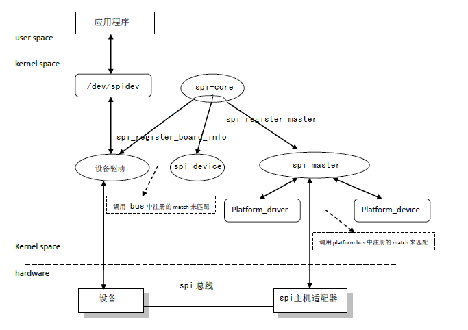
SPI驱动架构图:
总结:
真实的驱动包含platform、分层、分离等诸多概念,学习和领悟Linux设备驱动的软件架构思想,是将驱动的理论用于工程开发的必要环节。Linux内核目前有百多个驱动子系统,要掌握其规律,以不变应万变,以无招胜有招。